1
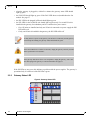
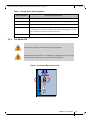
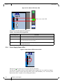
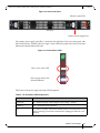
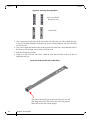
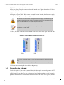
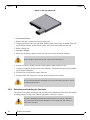
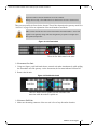
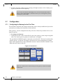
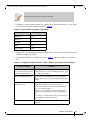
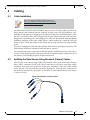
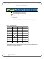
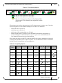
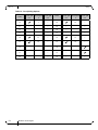
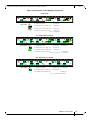
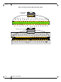
SwitchX 36-Port QSFP InfiniBand- Ethernet Gateway System Hardware User Manual 4 Cabling 4.1 Cable Installation Rev 1.0 For a list of approved cables for these gateway see http://www.mellanox.com/related-docs/user_manuals/ Mellanox_approved_cables.pdf All cables can be inserted or removed with the unit powered on. To insert a cable, press the connector into the port receptacle until the connector is firmly seated. The LED indicator, corresponding to each data port, will light when the physical connection is established (that is, when the unit is powered on and a cable is plugged into the port with the other end of the connector plugged into a functioning port). After plugging in a cable, lock the connector using the latching mechanism particular to the cable vendor. When a logical connection is made the LED will change to green for IB and orange for Eth. When data is being transferred the light will blink green. To remove, disengage the locks and slowly pull the connector away from the port receptacle. The LED indicator for that port will turn off when the cable is unseated. Care should be taken not to impede the air flow through the ventilation holes next to the connector ports. Cable lengths should be used which allow for routing horizontally around to the side of the gateway before bending upward or downward in the rack. 4.2 Splitting the Data Stream Using Breakout (Fanout) Cables Specific ports can be split by using a QSFP 1X4 breakout cable to split one 40 GbE port into 4 lanes (4 SFP+ connectors 10 GbE each). These 4 lanes then go, one lane to each of the 4 SFP+ connectors. Some ports can be split into 2 10 GbE ports, using lanes 1 and 2 only. When a QSFP port is split into 2 10 GbE ports then only SFP+ connectors #1 and #2 are used. Connectors #3 and #4 are left unconnected. Using Figure 36 and Table 18, with breakout cables you can achieve 13 ports of 10 Gb/s. Figure 35: Breakout or Fanout Cable Mellanox Technologies 51