1
KASvar
VFC-18
Elevator drive PLUS Emergency
Rescue
User manual
Thank you for choosing KASvar AC-AC
Power Inverter. Please take time to read the
following manual before installing the
power inverter. Please note that failure to
follow the proper procedures may result in
personal injury or damage to the Power
Inverter.
We wish our Inverter will serve you for
many years of high quality service and
reliability.
Safety and Warning
Please read the following information carefully before using
the Power Inverter:
Warning – Shock Hazard:
o DO NOT expose the Power Inverter to water, rain, snow or spray. Keep
the Power Inverter dry at all times.
o DO NOT connect the Power Inverter to power utility AC distribution
wiring or extension cords.
Warning – Heated Surface:
o DO keep all body parts and/or materials away from the Power Inverter
while in operation. The Power Inverter may become uncomfortably hot
during operating. If the Power Inverter overheats, it will automatically
shutdown.
o DO provide adequate ventilation to the Power Inverter. Ensure the Power
Inverter is never covered and always allow for proper ventilation.
Warning – Overload Situation:
o DO make sure the device you plug into the Power Inverter is less or equal
to 150 W. If the device plugged into the Power Inverter is more than 150
W, the Power Inverter will automatically shutdown to avoid an overload
of power.
Other Safety Precautions:
o DO NOT open the case of the Power Inverter. The high voltage inside the
case is the same type of power as your electrical outlets at home. Opening
case will automatically void the warranty.
o DO NOT expose this Power Inverter to flammable fumes or gases such as
a gasoline powered vehicle, or near any propane tanks.
o DO NOT use this Power Inverter in an enclosure containing automotiveType, lead-acid batteries to avoid hydrogen gas explosion, which can catch
Fire by sparks from electrical connections
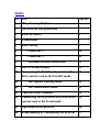
Index
NO
Title
Page no
1
Why choosing KASvar
6
2
The KASvar self-protection
7
3
KASvar classes
8
4
Diemensions
9
5
Basic wiring
9
6
Connector 1
10
7
Connector 2
11
8
Mechanical brake connection
11
9
The LCD and keypad
12
10
Connecting the KASVar Invertert to the
KAS control card in the Parallel mode
12
11
The regular working mode
12
12
The Maintenance mode
13
13
Control circuit terminal
14
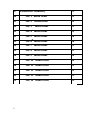
14
Connecting the KAS Invertert to the KAS
control card in the Serial mode
15
15
Operation of the KASvar
16
16
Programming & Configuring the KASvar
17
17
Parameters Summary
19
18
The 1st menu items
22
19
The 2nd menu items
22
20
The 3rd menu items
23
21
The 4th menu items
25
22
The 5th menu items
28
23
The 6th menu items
28
24
The 7th menu items
29
25
The 8th menu items
29
26
The 9th menu items
30
27
The 10th menu items
30
28
The 11th menu items
31
29
The 12th menu items
31
30
The 13th menu items
32
31
The 14th menu items
32
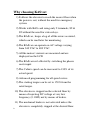
Why choosing KASvar:
1) It allows the elevator to reach the nearest floor when
the power is out, without the need for emergency
system.
2) Works with KAS card using only 2 terminals, S2 &
S2 without the need for extra relays.
3) The KASvar , keeps a log of all the errors occurred,
which can be read later for monitoring.
4) The KASvar can operate on AC voltage varying
from 340 VAC to 480 VAC.
5) All the motors' currents are measured and are
displayed on the LCD
6) The KASvar isn't affected by switching the phases
on its input.
7) The Cabin's speed can be increased to 130% of its
actual speed.
8) Advanced programming for all speed curves.
9) The starting torque can be set to 150% from the
rated torque.
10) The elevator is stopped on the selected floor by
means of injecting DC voltage at very low
frequency (0.1 HZ) not by means of brakes.
11) The mechnical brakes is not activated unless the
elevator is completely stopped at the desired floor.
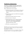
The KASvar self-protection:
The KASvar is equipped with many self-protection
circuits and mechanisms that make KASvar ideal in
many application and environments.
These self-protection circuits include:
1) Self-protection against any fluctuation in the power
network, whether it is increase or decrease in the
voltage.
2) Self-protection against any fault between any phase
and the ground.
3) Self-protection against motor over-current.
4) Protection timer at all speeds.
5) Separate protection circuit, separated from the
device itself, which insures an independent
protection system, not depending upon the
operation of the device itself.
6) The device can operate up to 85 .
The KASvar inverters have been tested in the worst operation
and environment conditions and it gave excellent results and
high stability and reliability.
All the KASvar inverter devices are tested prior to being sold in
the market and this is to assure high reliability and quality.
The protection circuits of the KASvar inverter devices are all
tested, to assure their operation if required when in the runtime.
KASvar inverter devices , were proved to be the best solution
when you need a hard-woking, reliable and stable inverter
device, for almost every use.
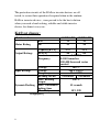
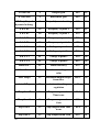
KASvar classes:
Model number
Motor Rating
KW
HP
Output Ratings
Capacity[KVA]
FLA[A]
Frequency
Voltage
Input Ratings
Voltage
Frequency
Braking circuit
Max. Braking
torque
Dynamic Barking Max. Continuous
baking time
Max Duty
Weight[KG]
11 KWATT
11
15
15 KWATT
15
20
17.5
46
22.9
60
0-400HZ
0-300 Sensorless
300-400 Sensored vector
control
380 V³
380 V ± 10%
50 ˜ 60 HZ
On Board
On Board
100 %
15 seconds
10% ED
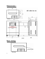
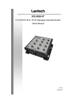
Diemensions :
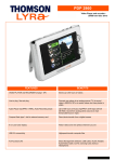
Basic wiring:
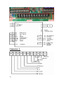
Connector 1:
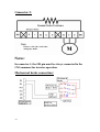
Connector 2:
Notes:
In connector 1, the OK pin must be always connected to the
CM (common) for inverter operation.
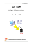
Mechanical brake connection:
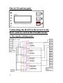
The LCD and keypad:
Connecting the KASVar Invertert to the
KAS control card in the Parallel mode:
1) The regular working mode:
2) The Maintenance mode:
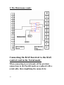
Connecting the KAS Invertert to the KAS
control card in the Serial mode:
When connecting in serial mode, all the previous
connections in the Parallel mode are replaced with a
serial cable, thus simplifying the connectivity.
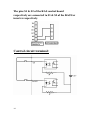
The pins S1 & S2 of the KAS control board
respectively are connected to S1 & S2 of the KASVar
inverter respectively.
Control circuit terminal:
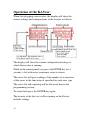
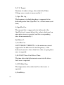
Operation of the KASvar:
When first plugging your inverter, the display will show the
current settings and configurations of the inverter as follows:
The display will show the current configurations/settings at
which the inverter is running.
While in the running mode you press the ENTER key for 5
seconds, a list with errors occurrence count is shown.
The errors list will give readings of the number of occurrences
of the errors in the time interval specified for each error type.
The errors list and capturing will be discussed later in the
programming section.
To return back press the ENTER key again.
The inverter at the first use will be running on the Factory
defaults settings.
The Factory settings are set to the most common settings taken
from the market and from the users of our inverters and are
updated on regular basis.
So in most cases, you will find the settings suit or at least very
close to your needs.
But if you decide to change the settings and customize the
inverter you have to enter the OEM-Programming menu and
change the settings according to your needs.
To enter the OEM-Programming menu, Press the Up and Down
keys together till the "OEM-Programming" appears on the LCD,
then release the Up and Down keys at the same time.
You will be then asked to enter the password of the
programming mode, it is set to 0000 initially , then you will
have the option to change it later from the programming menu.
To enter the password, press the ENTER key, this will allow
you to enter the first digit, Up/Down keys change the value of
the first digit.
Press Enter again, after you entered the first digit, and repeat
this procedure after all the digits is entered.
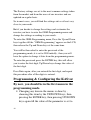
Programming & Configuring the KASvar
By now, you should be in the first menu in the
programming mode.
• Changing any item in the menus is done by ,
choosing this item by the UP/DOWN keys, then
pressing the ENTER key, then pressing UP/DOWN
keys again till the value of the parameter is set to
the desired value, then you press ENTER again, to
save the current value of the parameter.
• If the parameter you choose contains a sub-menu,
the sub-menu will open, and you will follow the
same procedure with every menu item in the submenu.
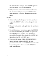
NOTE:
1. After you finished setting your inverter , you have
to press the RESET button for the changes to take
effect
2. The new settings will only apply after the inverter is
RESET.
3. To quit the menu at any instance, press the ENTER
key, then while hodling the ENTER key, press the
UP & DOWN keys together, keep all the keys
pressed for 2 seconds, then release the ENTER key,
then release the UP & DOWN keys.
4. If you quit the menus (OEM-PROGRAMMING
menus) without making a RESET, the new
parameter values will be saved, but the inverter will
be operating on the older values till a RESET is
done to the inverter.
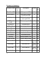
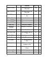
Parameters Summary:
Parameter name Menu
Description
no
Default Pa
ge
Motor Power KW
1
Motor power in KW
8.2
18
Rated frequency
1
Rated motor frequency
on name plate in Hz
50
18
High Speed
1
Maximum required
motor speed in Hz
43
18
MNT Speed
In Hz
1
Maintenance speed in Hz
20
18
OVLoad Cur
2
Overload current
130%
18
OVLoad Per
2
Overload period in sec
4.0
18
Accel. Time
2
Acceleration time in sec
4.0
19
Decel. Time
2
Deceleration time in sec
2.2
19
Acc. Pattern
3
Acceleration Pattern
L
19
Dec. Pattern
3
Deceleration Pattern
L
19
Start freq
3
Starting frequency in Hz
0.2
14
Change password
3
Change OEM password
0000
14
Error enables
4
Error enabling list
Details
page xxx
15
Errors timer
4
Error timers list
Details
page xxx
16
Error Count
4
Error counts list
Details
page xxx
16
Error Conditions
4
Errors occurrence
Details
16
conditions
page xxx
BRK ON Delay
5
Mechanical brake ON
delay time
0300
16
BRK OFF Delay
5
Mechanical brake OFF
delay time
0040
16
LOW Freq
5
Low Speed frequency in
Hz
05
16
DB on V level
5
In volts
060
16
Max BST TRQ
6
Maximum boost torque
11.0 %
17
Min BST TRQ
6
Minimum boost torque
00.1%
17
Emer freq
6
Emergency frequency
5.0
17
Emergency
OvLoad
6
Emergency OverLOAD
150%
17
DB offV level
7
In volts
030
18
LOW Freq. Time
7
Low frequency timer in
sec
10
18
Rest FRQ
7
Stop frequency in Hz
00.3
18
Rest Time
7
Stop Time in msec
0050
18
DC Inj.BrT
8
DC Injection braking
time
0.25
18
DC Inj.Br.F
8
DC Injection braking
frequency in Hz
01.9
18
DC Inj.Br.V
8
DC Injection braking
voltage
13%
18
Starting T
8
Starting torque
50%
18
P Gain PID
9
proportional gain
10%
19
I Gain PID
9
integral gain
18%
19
D Gain PID
9
differential gain
06%
19
DB Duty(Duty of
dynamic braking)
9
Duty of dynamic braking
11%
19
S & L F1
10
Frequency at point 1
50%
19
S & L F2
10
Frequency at point 2
15%
19
S & L F3
10
Frequency at point 3
50%
19
S & L F4
10
Frequency at point 4
15%
19
S & L V1
11
Voltage at point 1
15%
20
S & L V2
11
Voltage at point 2
78%
20
S & L V3
11
Voltage at point 3
15%
20
S & L V4
11
Voltage at point 4
60%
20
Motor Eff.:
12
Motor efficiency
85%
20
Motor Vrms
12
Rated motor voltage rms
value
380
20
Max Torq.o
12
Maximum output torque
from drive
180%
20
Auto V Reg.
12
Automatic voltage
regulation
01
20
Torq Com T
13
Torque compensation
Time in ms
02.0
21
Torq Com G
13
Torque compensation
Gain
80%
21
Slip Com T
13
Slip compensation Time
in ms
02.0
21
Slip Com G
13
Slip compensation Gain
02%
21
Motor poles
14
Number of the motor
poles
04
21
High T Offs
14
High Torque offset
30%
21
Low T Offs
14
Low Torque offset
10%
21
Midl T Offs
14
Middle Torque offset
20%
21
The 1st menu items are:
1) Motor Power:
The motor power in KW on name plate
2) Rated freq :
Rated motor frequency on name plate
3) High Speed:
Maximum required motor speed
4) MNT Speed:
Maintenance speed
The 2nd menu items are:
1) OVLoad Cur.:
Overload current, the maximum current that the
inverter can deliver to the load, %Rated current.
Default 120%
2) OVLoad Per.:
The Period over which the inverter will deliver the
OVERLOAD CURRENT, after this period the
inverter will cut-off its output .default 3 secs
3) Accel. Time:
Time taken for the motor to reach High speed from
0HZ
4) Decel. Time:
Time taken for the motor to reach High speed from
0 HZ
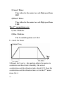
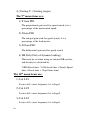
The 3rd menu items are:
1) Acc. Pattern:
2) Dec. Pattern:
The 2 available options are L & S
L: stands for linear
S:Stands for S-curve , this pattern allows the motor to
accelerate and decelerate smoothly, the actual
acceleration and deceleration takes about 40 % than the
acceleration and deceleration times set in the 2nd menu
items 3& 4.
3) Start freq.:
It is the frequency at which the inverter starts to
output its frequency.
4) Change password:
To change your OEM-programming password.
When you enter this menu, you will be asked for the
old password, after entering it , you will be asked for
the new password.
You press the enter key, the first digit will start to
blink, use the up/down keys to change the first digit,
after finished press ENTER key, to switch to the
second digit.
Repeat till all digits are entered, then press RESET for
the inverter to restart with the new password.
The 4th menu items are:
1) Error enables:
When entering this menu , a new submenu appears, it
shows the available errors that can happen, and let you
decide whether to capture and process them, or just
ignore the error when it happens.
If the error is set to yes (Y) the error is captured and
processed, if set to no (N) the error is ignored.
The errors are:
Ea, Over voltage error.
Eb Under voltage error
Ec phase u overload
Ed phase v overload
Ee phase w overload
Ef phase u open
Eg phase v open
Eh phase w open
Ei phase lost
Ej overheat
Ek excess current
2) Errors timer
3) Error Count
Items 2&3 work together, they set the maximum
number of the error to happen during specific time,
after that number of occurrence of specific error occurs
in the specified time, and assuming the corresponding
(Error enable ) for this error is set Y (yes) the inverter
stops working and is disconnected until a further
RESET is done to the inverter.
Note:
• If the corresponding error enable (item no.1 in menu 4
is set to N, the error is completely ignored, even its
timer and Count are set to values)
4) Error Conditions
When entering this menu, a sub-menu appears
In this menu you can indicate the conditions at which an error
is counted, in other words, what are the conditions for an
error to be counted in the ERROR COUNTER (current menu,
item 2 & 3)
This menu consists of 8 sub items, distributed into 2 menus.
Sub-Menu 1:
1) DBR. TIMER:
The time at which the Dynamic brake will stay ON.
2) U.V. Period:
Duration of under voltage, after which the Under
Voltage error counter is increased by 1.
3) Opn. Phs. frq :
The frequency at which the phase is supposed to be
delivering more than (Opn.Phs.Cur , current menu ,next
item)
4) Opn.Phs.Cur:
The current that is supposed to be delivered at the
Opn.Phs.frq, if current below this value is delivered, an
open phase error is reported, and the corresponding
error in incremented by 1.
Sub-Menu 2:
1) Lst.Phs.Cur.
LOST PHASE CURRENT, it is the minimum current
supposed to be delivered at rated frequency, if the
delivered current is lower than this value, an open phase
error is reported.
2) FLT.RST Time: Fault Reset Time.
The time after which the inverter resets itself, after a
fault error is reported
3) OVR Heat Deg:
The temperature after which an Over heat error is
reported.
4) FaultRelay:
The 5th menu items are:
1) BRK ON Delay:
Mechanical brake ON delay time.
2) BRK OFF Delay:
Mechanical brake OFF delay time.
3) LOW Freq:
Low Speed frequency.
4) DB on V level.
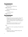
The 6th menu items are:
1) Max BST TRQ:
Maximum boost torque, increasing the starting torque
by means of increasing the output voltage of the
inverter. If the boost value is set too high than required,
it may cause the motor flux to saturate, causing over
current trip.
Increase the boost value when there is excessive
distance between the motor and the inverter.
Note:
the torque boost value is a percentage of the motor rated
voltage.
2) Min BST TRQ:
Minimum boost torque, at the Rated voltage of the
motor/F rated of the motor.
3) Emer freq:
Emergency frequency.
4) Emergency OvLoad:
Emergency OverLOAD
The 7th menu items are:
1) DB offV level
2) LOW Freq. Time :( Low frequency timer ) :
3) Rest FRQ. :(Rest frequency ) { Stop frequency }
4) Rest Time:Stop frequency time.
The 8th menu items are:
1) DC Inj.BrT.:(DC Injection braking time):
By introducing DC voltage to the motor windings, this
function stops the motor immediately.
DC injection braking time, is the time at which the DC
current is applied to the motor, after the DC braking
frequency is reached.
2) DC Inj.Br.F.: (DC Injection braking frequency)
It is the frequency at which the inverter starts to output
DC voltage to the motor during deceleration.
3) DC Inj.Br.V.: (DC Injection braking voltage)
The DC voltage applied to the motor, based on its rated
current.
4) Starting T.:( Starting torque)
The 9th menu items are:
1) P Gain PID:
The proportional gain used for speed search, it is a
percentage of the motor rated speed.
2) I Gain PID:
The integral gain used for speed search, it is a
percentage of the load inertia.
3) D Gain PID:
The differential gain used for speed search
4) DB Duty(Duty of dynamic braking) :
This must be set when using an external DB resistor,
and the duty is calculated by
%ED=Decel time * 100/(Accel time + Steady Speed
time + Decel time + Stop Status time)
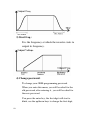
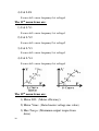
The 10th menu items are:
1) S & L F1
S-curve & L-curve frequency1 at voltage1
2) S & L F2
S-curve & L-curve frequency2 at voltage2
3) S & L F3
S-curve & L-curve frequency3 at voltage3
4) S & L F4
S-curve & L-curve frequency4 at voltage4
The 11th menu items are:
1) S & L V1
S-curve & L-curve frequency1 at voltage1
2) S & L V2
S-curve & L-curve frequency2 at voltage2
3) S & L V3
S-curve & L-curve frequency3 at voltage3
4) S & L V4
S-curve & L-curve frequency4 at voltage4
The 12th menu items are:
1) Motor Eff.: (Motor efficiency):
2) Motor Vrms: ( Rated motor voltage rms value)
3) Max Torq.o: (Maximum output torque from
drive)
4) Auto V Reg.: (Automatic voltage regulation)
00 for No and 01 for yes
The 13th menu items are:
1) Torq Com T: (Torque compensation Time)
2) Torq Com G: (Torque compensation Gain)
3) Slip Com T :(Slip compensation Time)
4) Slip Com G:(Slip compensation Gain)
The 14th menu items are:
1) Motor poles : Number of the motor poles.
2) High T Offs : High Torque offset
3) Low T Offs : Low Torque offset.
4) Midl T Offs: Middle Torque offset.