1
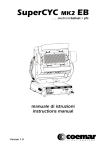
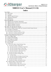
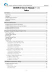
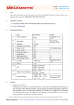
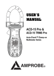
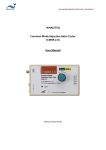
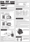
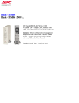
CellLog 8M Cell Voltage Monitor USER’S MANUAL SHENZHEN JUNSI ELECTRONIC CO.,LTD Cell Voltage Monitor CellLog 8M Thank you for purchasing the CellLog 8M. Please read the entire User‘s Manual completely and attentively as it contains a wide variety of specific programming and safety information. Specifications Lithium (LiPo/LiIo/LiFe) battery cell count: Pack voltage range: Alarm pack voltage range: Cell voltage range: Alarm cell voltage range: Voltage display resolution: Current loading of test: Maximum voltage for alarm port: Current drain for alarm port: Weight: Dimensions (L X W X D): 2 – 8 series 4.0 – 43.0VDC (USB can provide lower voltage 1.0V) 0.1 – 43.0VDC 1.3 – 4.9VDC 1.3 – 4.9VDC 1mV 8mA 50VDC <500mA 17g 62X39X12mm 2.44‖X1.53‖X0.47‖ Special features Small size with multiple functions, backlight 128*64 lattices LCD and Buzzer Tone Reminder; the interface can be operated smoothly. CellLog 8M can not only measure 2-8S Li battery individual voltage, but also measure NiMH, NiCd, Pb battery pack voltage. It can be set Individual Voltage Alarm and Pack Voltage Alarm, Overvoltage Alarm, Low Voltage Alarm, Differential Voltage Alarm and Time Over Alarm. What‘s more, the extra alarm output can be linkage controlled by the users. It has 8 sets default monitor alarm settings, which can be selected for different battery packs. CellLog 8M has been 100% calibrated before it enters to the market, at the same time, it supports the calibration by users themselves. -2- Cell Voltage Monitor CellLog 8M Unpack inspection The following items are included in the package. Contact your supplier if any items are missing. Standard items: CDROM 85 X 85mm One copy of the User’s manual on CDROM CW-C220 CW-P220 20mm 20mm One Alarm output line One pack voltage measurements line with clips Optional items: See details in ―Optional parts‖ (P14) -3- Cell Voltage Monitor CellLog 8M External controls and connections ③ ① ② ④ ⑤ 1. Input plug CellLog 8M 2. LCD screen 3. Function button 4. Beep 5. Alarm port Connection Diagram + 8 7 6 5 4 3 2 1 TYPE HOLD MENU + 8S - + 7S - PIN 9 6S - + 5S - + 4S - + 3S - + 2S - + 1S - PIN 9 8 7 6 5 4 3 2 1 + PIN 1 PIN 9 8 7 6 5 4 3 2 1 + 5S - + 4S - + 3S - + 2S - PIN 1 + 1S - -4- BATT. PACK (4—43V) 8 7 6 5 4 3 2 1 + PIN 1 Cell Voltage Monitor CellLog 8M Program flow chart Logo Screen CellLog POWER ON Inf. Screen S/N:XXXXXXXXXX CellLog 8M Ver X.X.X www.hillrc.com TYPE XXXXXXXXXX ⑤ Do not support the logging! Time is shown in the upper right corner blinkingly Data Hodling <HOLD> >3 Seconds ① <HOLD> >3 Seconds Voltage Monitor 1234567- 7S 28.79 6H 4.162 <▢> 1L 4.013 <▼> ▣V 149mV 14.013V 34.110V 54.087V 74.120V 24.150V 44.152V 64.162V 8------ 7S28.79V▣V149mV 14.0124.1534.11 44.1554.0864.16 74.128---- <▢> <▼> <▢> <▼> 7S HV LV ▣P 28.79V 28.80V 28.78V 0.020V Note: When you turn off the CellLog 8S it will remember the current screen and start from that screen when next turned on again. <TYPE> >3 Seconds <MENU> >3 Seconds ③ <MENU> >3 Seconds <▢>+<▼> ④ Select Type Details in Page 6 ② <MENU> >3 Seconds Search Results Details in Page 6 Main Menu MAIN MENU System... Calibration Tone Setting BEEP TONE SYSTEM SETTING Beep Tone LCD Screen ALM Output Start... Power Managemen Key Tone Hint Tone Alarm Tone LCD Brightness& Contrast Brightness - + ■■■■■■ Contrast - + ■■■■■■ Power Management ALM Output Setting POWER MANAGEMEN ALARM OUTPUT ⊙Not Save ○Backlight OFF ○Sleep Mode ⊙NO. ○NC. Start Setting START SETTING Start music Logo Screen Inf.Screen Calibration Select User Calibration 1------ 2-----3------ 4-----5------ 6-----7------ 8------ CALIBRATION ⊙Default ○User Setting Note: means if no operation on the button for 1 minutes, the system will return to monitor screen automatically. -5- Cell Voltage Monitor CellLog 8M ③ Select Type SELECT TYPE ⊙LiPo ○Lilo ○LiFe LiPo Select Rename Alarm ALARM SETTING Cells Voltag Pack Voltage Safety Timer Alarm Trigger CELLS ALARM VOLT HV 4.22V LV 3.00V ▣V 500mV Pack Alarm Voltage Setting PACK ALARM VOLT HV43.00V LV1.000V ▣P42.00V SAFETY TIMER Minutes(1-999) 120 Alarm Trigger Select ALARM TRIGGER Over Voltag Low Voltage Difference Time Over <MENU> >3 Seconds <TYPE> >3 Seconds Note: ① means if no operation on the button for 1 minutes, Voltage Monitor the system will return to monitor screen automatically. <▢>+<▼> <MENU> >3 Seconds Search Results ④ 00m:00 1234567- 7S 28.79 6H 4.162 <▢> 1L 4.013 <▼> ▣V 149mV 00m:00 14.013V 34.110V 54.087V 74.120V 24.150V 44.152V 64.162V 8------ Star t Location <▢> <▼> 00m:00 7S28.79V▣V149mV 14.0124.1534.11 44.1554.0864.16 74.128---- <▢> <▼> 7S HV LV ▣P 28.79V 00m:00 28.80V 28.78V 0.020V Note: The upper right corner of the screen will alternatively blink time 00m: 00 <MENU> 50m:20 1234567- 7S 21.79 6H 3.162 <▢> 1L 3.013 <▼> ▣V 149mV 50m:20 13.013V 33.110V 53.087V 73.120V 23.150V 43.152V 63.162V 8------ Ending Location <▢> <▼> 50m:20 7S21.79V▣V149mV 13.0123.1533.11 43.1553.0863.16 73.128---- <▢> <▼> 7S HV LV ▣P 21.79V 50m:20 21.80V 21.78V 0.020V Note: The upper right corner of the screen will alternatively blink ending time xxx:xx 48m:10 1Low 3-----5-----7------ -6- <MENU> 2-----4-----6-----8------ Alarm time points If there is alarm, the alarm events/alarm time will be shown alternatively at the corresponding battery number place. Cell Voltage Monitor CellLog 8M Menu Operation: 1. Select the menu items by <▲> /<▼> buttons, the selected item will be shown in white. 2. Press < > to the following menu, and hold < >for more than 3 seconds, it will return to the upper menu. Symbol Meanings: Display Symbols The meaning of the Symbols Note nS total voltage of the pack n:0-8, the cell count nH the highest individual cell voltage n:0-8, the highest cell number nL the lowest individual cell voltage n:0-8, the lowest cell number ▣V the maximum voltage difference between the cells ▣V = nH - nL HV The voltage maximum value LV the voltage minimum value ▣P the pack maximum voltage difference ▣P = HV - LV mmM:ss or hhH:mm the time entering to logging ss:second ,mm:minute , hh: hour ⊙/○ Single choice Do/Do not /□ Multiple choice Do/Do not T_OVER LOW OVER DIFF Safety time alarm Low voltage alarm Over voltage alarm Voltage difference alarm Button Function CellLog has 3 buttons, which everyone owns the first and second functions. The first function is trigger after only one click; the second function is trigger after 3 seconds holding of the button. Press button Condition Button Function Description <▲> Click 1. 2. 3. Hold for 3 seconds Enter to Alarm type select menu Click 1. 2. 3. Hold for 3 seconds Trigger Open/Close Logging Function Click Confirmation Hold for 3 seconds Enter to System Setting Menu Click Check holding information Hold for 3 seconds Save users voltage calibrated value <▼> < > <▲>+<▼> Turns up the menu Increase the value Select the character input Turns down the menu Decrease the value Delete the character Note:<▲>+<▼> means pressing <▲> and <▼> at the same time. -7- Cell Voltage Monitor CellLog 8M QUICK START CellLog Power On (2 ways: one is connecting the battery through the left 9 Pin socket, the other one is through the USB port), System self-check, and then shows the SN and version number, the display information are as below: TYPE XXXXXXXXXX Alarm configuration Name The first line is the current selected Setting Type (See detail in P10). Do not support the logging! Notes Note: CellLog 8M has no Logging function, if it is necessary, please choose CellLog 8S. Voltage Monitor There are 4 interface choices, which can be shifted by <▲> or <▼>buttons. As the left pictures: the ‘7‘ in ‖7S‖ means cell counts; ‘6H‘ means the 6th cell voltage is the highest; ‘1L‘ means the 1st Cell Number 1234567- 7S 28.79 Pack Voltage 6H 4.162 The highest voltage cell voltage is the lowest. 1L 4.013 The lowest voltage Voltage If the monitor voltage trigger alarm, the corresponding ▣V 149mV The maximum Histogram voltage difference voltage and alarm display (LOW, OVER or DIFF) shows <▢> <▼> alternatively. Cell Number 14.013V 24.150V Cell Voltage The cell number and (L, O, D) shows alternatively. 34.110V 44.152V 54.087V 64.162V 74.120V 8-----<▢> <▼> Pack Voltage 7S28.79V▣V149mV Cell Number 14.0124.1534.11 44.1554.0864.16 74.128---<▢> 7S HV LV ▣P The Max. Voltage difference Cell Voltage ‘LOW‘ or ‗L‘ means: Low voltage alarm ‘OVER‘ or ‗O‘ means: Over voltage alarm ‘DIFF‘ or ‗D‘ means: Voltage difference alarm. They will be displayed at the same time at the highest and the lowest cell voltage interface. <▼> 28.79V 28.80V 28.78V 0.020V Monitor the pack voltage Pack Voltage Max. Pack Voltage Display respectively: Current pack voltage, Max. Pack Min. Pack Voltage Pack Voltage Difference voltage, Min. Pack voltage, Pack voltage difference. (▣P = HV-LV) Data Holding When in Voltage Monitor status, press <▼> button for 3 seconds, after it shows ‖Start holding…‖, the calculagraph will be shown alternatively at the upper right corner of the LCD screen. Press <▼> for 3 seconds again, the screen will show ‖Stop holding!‖ and then exit. View holding Point In the monitor status, press <▲> and <▼> at the same time to enter the view logging point status. Three points voltage data can be searched:‖Starting holding…‖data, ‖Stop holding!‖ data, and the data of voltage alarm during this period , which can be shifted by < > buttons. Press < > for 3 seconds,it will return to the monitor status. The saved data can be covered till next logging. If the logging time is over the users setting safety time,(See Monitor Safety Time Setting in P11), it will trigger Safety Time Alarm, and the screen shows ‖T_OVER‖ alternatively in the upper right corner. -8- Cell Voltage Monitor CellLog 8M Alarm Remind If CellLog detect the alarm events (See Alarm Trigger Settings in P11), it will remind as below: 1. The buzzer beeps every 4 seconds( 【Alarm Tone】is selected , See P12). 2. The corresponding individual voltage and alarm remind show alternatively. Alarm Remind Information: ―LOW‖, ―OVER‖, ―DIFF‖, ―T_OVER‖ 3. ALM port will output the presetting signal. ALM port signal information: ALM output port signal is open collector signal, as showed below. + ALM Output - Q9 Please pay attention to the port voltage and current limit when you use(<50V,<500mA) The following are ALM Output typical application. VCC VCC R Output + - Output ALM Level Output + - ALM Relay Output -9- Cell Voltage Monitor CellLog 8M Monitor Alarm Settings The system can have 8 sets alarm settings, press <▲> for 3 seconds to enter SELECT TYPE menu. SELECT TYPE ⊙LiPo ○Lilo ○LiFe The item with is the current setting. <▲> or <▼> to select items and press < > button. Defaulted TYPEs are: LiPo, Lilo, LiFe, User1--5 < > LiPo Select Rename Alarm Note: Operate the selected type settings <▲> or <▼> to select the items, press < > to enter to the next step. See details below. Press<▲> button to power on, it will shift to LiPo Type automatically. Press <▼> button to power on, it will shift to Lilo Type automatically. Press < > button to power on, it will shift to LiFe Type automatically. Change Current Alarm Type: Select【Select】, Press < > then the item will be with , and the settings come into effect. Rename Alarm Type: Select【Rename】, press < > and the screen shows: New Name Input Method: <▲> to select characters, hold it to trigger LiPo continuously; <▼> to delete the current character; < > to confirm the Rename New Name selected character; press < > for 2 times to confirm the amendment LiPo-1200mAh and return; press < > for 3 seconds to cancel and return. Alarm Parameters Setting: Select【Alarm】, press < > and the screen shows: <▲> or <▼> to select items, press < > enter to the next step ALARM SETTING See details below. Cells Voltag Pack Voltage Safety Timer Alarm Trigger 1) Individual Cell Voltage Alarm Settings: Select【Cells Voltage】, press < > and the screen shows: <▲> or <▼> to increase/decrease voltage value, press < > to shift CELLS ALARM VOLT HV 4.22V Cell Alarm Upper Limit setting items. Press < > for 3 seconds to confirm amendment and LV 3.00V Cell Alarm Lower Limit return. ▣V 500mV Cell Alarm Difference HV : 1.31V—4.90V LV: 1.30V—4.89V ▣V: 0.01—3.60V 2) Pack Alarm Voltage Setting: Select【Pack Voltage】, press < > and the screen shows: <▲> or <▼> to increase/decrease voltage value, press < > to shift PACK ALARM VOLT Pack Alarm Upper Limit setting items. Press < > for 3 seconds to confirm amendment and HV43.00V LV1.000V Pack Alarm Lower Limit return. ▣P42.00V Pack Alarm Difference HV: 1.05V—43.00V LV: 1.00V—42.95V ▣P: 0.05—42.00V -10- Cell Voltage Monitor CellLog 8M 3) Monitor Safety Time Setting: Select【Safety Timer】, press < > and the screen shows: <▲> or <▼> to increase/decrease, press < > to confirm amendment SAFETY TIMER Minutes(1-999) and return. Press< > for 3 seconds to cancel amendment and return. 120 Safety Time Setting range: 1-999 minutes 4) Alarm Trigger Settings: Select【Alarm Trigger】, press < > and the screen shows: <▲> or <▼> to select items, press < > to shift select /, ALARM TRIGGER press< > for 3 seconds to confirm amendment and return. Over Voltag Select【Over Voltage】Cell or pack voltage are over HV setting value, Low Voltage Difference then it alarms. Time Over Select【Low Voltage】Cell or pack voltage are lower LV setting value, then it alarms. Select【Difference】Cell voltage is over ▣V or the pack voltage difference is over ▣P setting value, then it alarms. Select【Time Over】 entering HOLD status time is over setting safety time ,then it alarms. -11- Cell Voltage Monitor CellLog 8M Parameter Setup Press < > for 3 seconds, and enter to the MAIN MENU, Monitor status. MAIN MENU System... Calibration System Settings: Select【System…】, press < >, the screen shows: <▲> or <▼> to select items, press < > to have a select item, press SYSTEM SETTING < > for more than 3 seconds to return. Beep Tone LCD Screen See details below. ALM Output 1) Beep Tone Settings: Select【Beep Tone】, press < >, the screen shows: <▲> or <▼> to select the items, and press < > to shift select /, BEEP TONE press < > for 3 seconds to confirm the amendment and then return. Key Tone Select【Key Tone】,the buttons tone open. Hint Tone Alarm Tone Select【Hint Tone】,the status tone open. Select【Alarm Tone】,the alarm tone open. (―Do‖ every 4 seconds) 2) LCD Brightness & Contrast Setting : Select【LCD Screen】, press < >, the screen shows: <▲> increase, <▼> decrease, and press < > to shift Brightness - ■■■■■■ + Brightness/Contrast, press < > for 3 seconds to confirm the Contrast amendment and then return. - ■■■■■■ + 3) Alarm Output Signal Type Setting:【ALARM Output】 【NO.】: Always On. Two output of ALM, it‘s open when there is no ALARM OUTPUT alarm; It‘ short circuit with alarm. ⊙NO. ○NC. 【NC.】: Always Close. Two output of ALM, it‘s short circuit when there is no alarm; It‘s open with alarm. 4) Start-up Setting:【Start…】 <▲> or <▼> to select the items, and press < > to shift select /, press < > for 3 seconds to confirm the amendment and then return. Select【Start Music】, there will be a start music if you turn on Select【Logo Screen】, it will display Logo Screen if you turn on Select【Inf. Screen】, it will display Information Screen if you turn on START SETTING Start Music Logo Screen Inf.Screen 5) Power management Setting:【Power management】 The item with is the current setting. POWER MANAGEMEN 【Not Save】, power save function turns off ⊙Not Save ○Backlight OFF 【Backlight OFF】, turns off LCD backlight ○Sleep Mode 【Sleep Mode】, turns off LCD backlight & MCU enters to Sleep Mode < > SAVE TIME SET Minutes(1-240) 005 Save Time Set Press < > to【Save Time Set】 No operation in setting time, the system will enter to the selected Power Save Mode automatically. Press any key to normal Mode. -12- Cell Voltage Monitor CellLog 8M Calibration Settings: Select【Calibration】, and press < >, the screen shows: 【Default】: Calibration Default. CALIBRATION 【User Setting】: See details in P13 ⊙Default ○User Setting User Calibration The CellLog 8M has been calibrated before entering to the markets, but if the users find that there is too much deviation, and then they can calibrate it as the following items: Before calibration, you need prepare: 8s battery pack (the individual voltage ranges from 3.8-4.2V) 1 42 Digital Multimeter Calibrating steps: 1. Connect pack balance port to CellLog 8M to confirm there are 8 cell voltage display. 2. Press <MENU> for 3 seconds to enter Main Menu--【Calibration】-> CALIBRATION--【User Setting】,then it shows: , 14.012V 34.018V 54.022V 74.002V 24.032V 44.015V 64.017V 84.019V 3. The current need-to-be calibrated voltage begins to blink(shows the voltage and calibrated value alternatively), and use multimeter to measure the individual voltage corresponding to the blinking voltage. If the displayed value is more than the measured value, please press <▼> to decrease the displayed value to the measured value; vice versa, please press <▲> to increase the displayed value to the measured value. Press < > and shift to the next voltage calibration. In this way to get 8 sets voltage calibration. 4. Press <▲> and <▼> for 3 seconds to save the amendment and exit; Press < > for 3 seconds, it will cancel the amendment and exit. 5. The above is only for 8S individual cell measurement calibration, the methods are same for CellLog 8M measure port 1, 2 to measure pack voltage calibration. Connect 1, 2 to the battery pack‘s negative and positive pole respectively, then follow the Step 2, 3, 4. 132.12V 3-----5-----7------ 2-----4-----6-----8------ Note: If the user calibrates it in a wrong way, which damage the battery or cause other serious danger, our company will be of no responsibility. The users’ calibrated value will not affect the calibrated before entering to the market. It can be selected by CALIBRATION--【User Setting】or【Default】. -13-