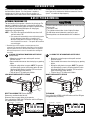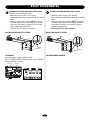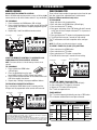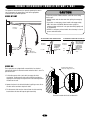
1
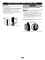
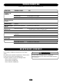
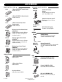
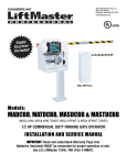
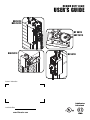
MEDIUM DUTY LOGIC
USER’S GUIDE
MH 5011E
MHS 5011E
MT 5011E
BMT 5011E
MGJ 5011E
MJ 5011E
Contact Information
Radio Receiver
Built on Board
Installation Date
www.liftmaster.com
315MHz
INTRODUCTION
Congratulations on purchasing a quality, LiftMaster Medium Duty
Commercial Door Operator. Your new operator is capable of
operating up to 12 cycles per hour or 50 cycles per day. It is
equipped with a built in radio receiver that is compatible with our
existing 315 MHz product line as well as a Timer To Close (TTC)
feature that can be enabled when LiftMaster Commercial Protector
System® is installed and aligned properly.
BASIC PROGRAMMING
DETERMINE THE WIRING TYPE
CAUTION
The functionality of this operator is based on the wiring type. The
operator is shipped from the factory in standard C2 wiring type
(factory default). Some wiring types will require an optional safety
device. Refer to the following descriptions of wiring types,
requirements and programming.
To prevent possible SEVERE INJURY or DEATH, install reversing
sensors when:
• The radio is used.
• The 3-button control station is out of sight of the door.
• Or ANY other control (automatic or manual) is used.
Reversing devices are recommended for ALL installations.
NOTE: 1. The LED on the logic board will blink once when in C2
and twice when in B2.
2. The operator will automatically convert to B2 wiring (option
D) when Monitored Safety Device is installed. If the
Monitored Safety Device is removed, the operator will go
into a Restricted Close mode**. Turn power OFF and ON to
reset wiring type.
** Restricted close mode requires a constant pressure close
command. The operator will begin closing after a 5 second delay
and will continue to close to the close limit switch. The operator
will stop if the pressure to close is released before reaching the
close limit.
A
WARNING
AVERTISSEMENT
C2 WIRING TYPE WITHOUT MONITORED SAFETY DEVICE
(Factory Default)
B
• Momentary contact to open and stop with constant
pressure to close.
• Open override that reverses when closing by any opening
device.
• Wiring for safety device to reverse. NOTE: The operator
will automatically convert to B2 wiring (option D) when
Monitored Safety Device is installed. (See accessories
page for Monitored Safety Devices)
• Timer to Close (TTC) feature not available.
NON-MONITORED SAFETY DEVICE
ATTENTION
C2 WIRING TYPE WITH MONITORED SAFETY DEVICE
• Momentary contact to open and stop with constant
pressure to close.
• Open override that reverses when closing by any opening
device.
• Wiring for safety device to reverse. NOTE: The operator
will automatically convert to B2 wiring (option D) when
Monitored Safety Device is installed. (See accessories
page for Monitored Safety Devices)
• Timer to Close (TTC) feature not available.
MONITORED SAFETY DEVICE
ADVERTENCIA
Sensing
Edge
Photo Eye
PRECAUCIÓN
RESET TO C2 WIRING TYPE (Factory Default)
Remove any monitored safety devices.
Disconnect then reconnect power to the operator.
Press and hold the LEARN and STOP buttons until the LED goes
out (approximately 3 seconds).
Electrical Box
TO PROGRAM
Press and hold the LEARN and CLOSE buttons until the LED goes
out (approximately 3 seconds).
Logic Board
Electrical Box
LEARN
STOP
Logic Board
CLOSE OPEN
LEARN
D14
LED
D7
U4 D6
014A1030
C20
D4
D7
U4 D6
R25
014A1030
C20
TP1
L5
D5
D4
J4
C32
R25
C9
^^^^
C31
U1
C21
CLOSE OPEN
C32
C31
TP1
C9
AUX
AUX ANT
ANT
STOP
D14
LED
D5
J4
U1
C21
C18
R27
J2
L5
LEARN STOP CLOSE OPEN
LED
D9
^^^^
AUX
AUX ANT
ANT
D14
TTC
1
2
3
4
5
6
7
LMEP1
LMEP2
COM
INTRLK
STOP
CLOSE
OPEN
K2
LT
C29
R24
P1
C18
1
2
3
4
5
6
R27
J2
7
D14
TTC
LEARN STOP CLOSE OPEN
LED
D9
2
1
2
3
4
5
6
7
LMEP1
LMEP2
COM
INTRLK
STOP
CLOSE
OPEN
K2
LT
C29
R24
P1
1
2
3
4
5
6
7
BASIC PROGRAMMING
B2 WIRING TYPE WITHOUT MONITORED SAFETY DEVICE
C
D
Requires a non-monitored safety device.
• Momentary contact to open, close and stop.
• Open override that reverses when closing by any opening
device.
• Wiring for safety device to reverse. NOTE: The operator
will automatically convert to B2 wiring (option D) when
Monitored Safety Device is installed. (See accessories
page for Monitored Safety Devices)
• Timer to Close (TTC) feature not available.
B2 WIRING TYPE WITH MONITORED SAFETY DEVICE
• Momentary contact to open, close and stop.
• Open override that reverses when closing by any opening
device.
• Wiring for safety device to reverse. NOTE: The operator
will automatically convert to B2 wiring when Monitored
Safety Device is installed. (See accessories page for
Monitored Safety Devices)
• Timer to Close (TTC) feature available.
NON-MONITORED SAFETY DEVICE
MONITORED SAFETY DEVICE
Sensing
Edge
Photo Eye
TO PROGRAM
NO PROGRAMMING REQUIRED
Start with operator in factory default C2 mode.
Press and hold the LEARN and CLOSE buttons until the LED goes
out (approximately 3 seconds).
Electrical Box
Logic Board
D7
U4 D6
014A1030
C20
D5
D4
J4
C32
R25
C31
TP1
C9
U1
C21
LEARN
L5
^^^^
AUX
AUX ANT
ANT
C18
R27
J2
STOP
CLOSE OPEN
D14
TTC
LEARN STOP CLOSE OPEN
LED
D9
1
2
3
4
5
6
7
LMEP1
LMEP2
COM
INTRLK
STOP
CLOSE
OPEN
K2
LT
C29
R24
P1
D14
LED
1
2
3
4
5
6
7
3
BASIC PROGRAMMING
REMOTE CONTROLS
TIMER TO CLOSE (TTC)
SINGLE BUTTON REMOTE CONTROL
Built in 315 MHz radio receiver permits as many as 20 Security✚®
remote controls or dip switch remote controls in any combination.
Timer to Close feature enables the operator to close from the open
limit after a preset time, adjustable from 5 to 60 seconds.
Requires LiftMaster monitored safety device.
TO PROGRAM
1. Press and release the LEARN button (LED will light).
2. Press and hold the button on the remote control until the LED
flashes rapidly, then release to complete programming (LED
will go out).
3. Repeat steps 1 and 2 for additional remote controls.
TO PROGRAM
1. Begin with door in fully closed position.
2. Press and release the LEARN button (LED will light).
3. Press and release the TTC button.
4. Every press and release of the STOP button will add 5 seconds
to the Timer to Close. Example: 30 second TTC = 6 presses of
the STOP button.
5. Press and release the TTC button to exit programming mode.
6. The LED will flash once per 5 seconds of timer setting.
The TTC will become active after completion of the next open
cycle.
Electrical Box
Logic Board
STOP
LEARN
CLOSE OPEN
D14
LED
D7
U4 D6
NOTE: The LED does not indicate that timer is running.
D5
D4
J4
014A1030
C32
C20
R25
C31
TP1
C9
U1
C21
L5
^^^^
AUX
AUX ANT
ANT
C18
R27
J2
K2
LT
LEARN STOP CLOSE OPEN
C29
R24
P1
LED
D9
1
2
3
4
5
6
7
LMEP1
LMEP2
COM
INTRLK
STOP
CLOSE
OPEN
2
1
D14
TTC
3
4
5
OPEN
6
7
TO VERIFY TIMER TO CLOSE (TTC) SETTING
1. Press and release the LEARN button.
2. Press and release the TTC button.
3. Press and release the TTC button a second time.
4. The LED will flash once per 5 seconds of timer setting.
MEP1 LMEP2 COM INTRLK STOP CLOSE OPEN
3-BUTTON REMOTE CONTROL TO OPERATE AS A
WIRELESS 3-BUTTON CONTROL STATION
Logic Board
Electrical Box
Timer To Close Button
NOTE: The feature will use 3 of the 20 memory channels in the
operator.
D7
U4 D6
014A1030
D7
U4 D6
014A1030
C20
D5
D4
J4
C32
C31
U1
1
^^^^
C18
2
3
4
5
R27
D14
TTC
LEARN STOP CLOSE OPEN
LED
D9
1
2
3
4
5
6
7
LMEP1
LMEP2
COM
INTRLK
STOP
CLOSE
OPEN
K2
LT
C29
R24
P1
LMEP1 LMEP2 COM INTRLK STOP CL
CLEAR THE TIMER TO CLOSE (TTC)
1. Press and release the LEARN button (LED will light.)
2. Press and hold the TTC button for 6 seconds.
3. Release the TTC button (LED will go out).
The TTC will no longer be active.
TIMER DEFEAT
The TTC can be temporarily disabled by pressing a STOP button.
TTC will become enabled after the next open command.
CLOSE OPEN
D14
LED
D5
D4
J4
C32
R25
C9
C31
TP1
CLO
R25
C21
L5
J2
Logic Board
STOP
C20
TP1
C9
AUX
AUX ANT
ANT
TO ERASE ALL REMOTE CONTROLS
Press and hold the LEARN button (over 5 seconds) until the
LED goes out. All programmed remote controls will be erased.
LEARN
STOP
D14
LED
TO PROGRAM
Open
1. Press and hold the LEARN button
Close
Stop
(LED will light).
2. Press the desired button on the logic
board (OPEN, CLOSE or STOP). Release both buttons.
3. Press and hold the desired button of the remote control until
LED flashes rapidly, then release.
4. Repeat steps 1 through 3 to program additional buttons.
Electrical Box
LEARN
TTC
U1
C21
L5
^^^^
AUX
AUX ANT
ANT
C18
R27
J2
D14
TTC
LEARN STOP CLOSE OPEN
LED
D9
1
2
3
4
5
6
7
LMEP1
LMEP2
COM
INTRLK
STOP
CLOSE
OPEN
K2
LT
C29
R24
P1
1
2
3
4
5
6
7
RADIO OPERATION
MODE
OPEN
CLOSE
STOP
B2
B2
with
TTC
C2
X
X
X
(3 button
remote)
X
X
X
X
X
X
MEP1 LMEP2 COM INTRLK STOP CLOSE OPEN
NOTICE: To comply with FCC and or Industry Canada (IC) rules, adjustment or modifications of this
receiver and/or transmitter are prohibited, except for changing the code setting or replacing the
battery. THERE ARE NO OTHER USER SERVICEABLE PARTS.
Tested to Comply with FCC Standards FOR HOME OR OFFICE USE. Operation is subject to the
following two conditions: (1) this device may not cause harmful interference, and (2) this device
must accept any interference received, including interference that may cause undesired operation.
4
X
X
REVERSE WHILE
CLOSING
TTC
RESET
X WHEN
OPEN
WARNING
MANUAL DISCONNECT (MODELS MT/B
MT & MH)
The operators have provisions for manually operating the door in
case of emergency or power failure. Refer to the appropriate
instructions for your model operator.
CAUTION
To prevent possible SERIOUS INJURY or DEATH from a falling
door or arm:
• DO NOT stand under the door arm when pulling the emergency
release.
• If possible, use emergency release handle to disengage trolley
ONLY when door is CLOSED. Weak or broken springs or
unbalanced door could result in an open door falling rapidly and/
or unexpectedly.
• NEVER use emergency release handle unless doorway is clear of
persons and obstructions.
MODEL MT/BMT
Emergency
Disconnect
AVERTISSEMENT
TO DISCONNECT DOOR FROM OPENER
Emergency
Disconnect
Door Arm
NOTI
C
E
Door
TO RECONNECT DOOR ARM TO TROLLEY
ATTENTION
Pull emergency
release handle
straight down.
Emergency
disconnect will
open.
Emergency
Disconnect
Door
Arm
Emergency
Release Handle
Lift free end of door
arm to trolley. Pull
emergency handle
to allow arm to
engage roll pin.
Release handle.
Emergency
disconnect will
close.
MODEL MH
Chain Retaining Bracket
(with pad locking provisions)
These operators are equipped with a manual hoist. An electrical
interlock will disable the electrical controls when the hoist is used. To
operate the hoist:
ADVERTENCIA
1. Pull the disconnect chain (sash chain) to engage the hoist
mechanism. The disconnect chain may be locked in position by
slipping the end through the keyhole of the chain retaining bracket
mounted on the wall.
PRECAUCIÓN
2. Operate the door in the desired direction by pulling on one side or
the other of the continuous loop hoist chain.
3. The disconnect chain must be released from the chain retaining
bracket before the door will operate again electrically.
Electrical Interlock with Hoist for Model MH
5
WARNING
MANUAL DISCONNECT (MODELS MJ/MGJ & MHS)
MODEL MJ/MGJ
CAUTION
This operator has a floor level disconnect chain to disconnect the
door from the door operator.
1. To disengage, pull the chain and secure in the disengaged position
by slipping the end through the keyhole bracket mounted on the
wall. Or if emergency egress device is used, pull handle to
disengage operator from door.
2. The door may now be pushed up or pulled down manually.
3. Release the disconnect chain or reset the emergency egress device
to operate the door again electrically.
To prevent possible SERIOUS INJURY from a moving chain,
DISCONNECT electric power to the operator BEFORE manually
operating your door.
MODEL MHS
This operator includes two methods of manual operation:
1. A disconnect sash chain for push-up/pull-down operation. This
chain can be found on the hoist side of the operator. See Manual
Disconnect - Model MJ/MGJ for instructions.
2. A hoist engagement sash chain for manual hoist operation. This
chain can be found on the clutch side of the operator. See Manual
Disconnect - Model MH for instructions.
AVERTISSEMENT
Keyhole Bracket
When operator is disconnected by the manual operation chain, hoist
and electrical operation will not function.
ATTENTION
Chain Retaining Bracket
(with pad locking provisions)
Hoist Chain
Manual Disconnect for Models MJ and MGJ
Electrical Interlock with Hoist Chain (when present) for Model MHS
ADVERTENCIA
PRECAUCIÓN
6
WARNING
TESTING
Turn on power, LED will flash 7 times on power up. Test all
controls and safety devices to make sure they are working
properly. If the operator does not function properly, contact your
installing dealer.
CAUTION
WARNING
WARNING
To avoid SERIOUS PERSONAL INJURY or DEATH from
electrocution, disconnect ALL electric power BEFORE performing
ANY maintenance.
IMPORTANT NOTES:
• Do not leave power to the operator on unless all safety and
entrapment protection devices have been tested and are working
properly.
• Be sure you have read and understand all safety instructions
included in this manual.
• Be sure the owner or person(s) responsible for operation of the
door have read and understand the safety instructions, know how
to electrically operate the door in a safe manner and how to
manually disconnect the door from the operator.
TEST THE SAFETY DEVICES (IF INSTALLED)
1. Open the door.
2. Place an obstruction in the path of the photo eyes or sensing
edge.
3. Press the CLOSE button.
The door should not close if photo eyes are installed. The door
should close to obstruction and reverse if sensing edge is
installed.
4. Remove the obstruction.
5. Press CLOSE button. Door should close.
If door did not reverse from obstruction, check safety devices.
AVERTISSEMENT
AVERTISSEMENT
TEST 3-BUTTON CONTROL STATION
1. Press OPEN button. (The door should move in the open
direction.)
2. Press STOP button. (The door should stop.)
3. Press CLOSE button. (The door should move in the close
direction.)
4. Release CLOSE button. Door should stop if in C2 mode. (The
door should continue closing if in B2 mode.)
5. Press STOP button. (The door should stop.)
ATTENTION
AVERTISSEMENT
TEST REMOTE CONTROL
* Requires B2 wiring type and compatible LiftMaster remote
control. In C2 wiring the remote control will open the
door only.
1. Press remote control button.
2. Door should open. Allow the door to fully open.
3. Press remote control button.
4. Door should close. Allow door to fully close.
TEST LIMIT ADJUSTMENT
1. Press OPEN button. (The door should open.)
2. Allow the door to fully open.
3. Press CLOSE button. (The door should close.)
4. Allow the door to fully close.
5. If the limits are not set properly, contact your installing dealer.
ADVERTENCIA
ADVERTENCIA
ADVERTENCIA
PRECAUCIÓN
7
TROUBLESHOOTING
To locate a dealer in your area visit us online at www.liftmaster.com
CONDITION
POSSIBLE CAUSE
FIX
OPERATOR WILL NOT
RESPOND TO ANY
COMMANDS
No power
➤ Check circuit breaker.
Accessory failure
➤ Verify photo eyes are aligned.
Possible component failure
➤ Contact your installing dealer.
OPERATOR MAKES
NOISE BUT DOOR DOES
NOT MOVE
Operator requires adjustment
➤ Contact your installing dealer.
DOOR DRIFTS AFTER
OPERATOR STOPS
Operator or door requires
adjustment
➤ Contact your installing dealer.
DOOR OPENS/CLOSES
TOO FAR
Operator requires adjustment
➤ Contact your installing dealer.
DOOR REVERSES
UNEXPECTEDLY
Safety device activated
➤ Verify photo eyes are aligned. If photo eyes are aligned and operator still does
not operate properly, contact your installing dealer.
Remote control is not
programmed
➤ See PROGRAMMING REMOTE CONTROLS section.
Low battery
➤ Replace battery.
REMOTE CANNOT BE
PROGRAMMED
Low battery
➤ Replace battery.
POOR RANGE
Low battery
➤ Replace battery.
Possible radio interference
➤ Contact your installing dealer.
RADIO FUNCTIONALITY
NO RESPONSE
MAINTENANCE SCHEDULE
Every 3 months or 5,000 cycles repeat all tests in the Testing
section.
Call qualified service contractor for maintenance. To locate a dealer
in your area visit us online at www.liftmaster.com.
The operator should be serviced at the following intervals:
• Every 3 months or 5,000 cycles
• Every 6 months or 10,000 cycles
• Every 12 months or 20,000 cycles
WARNING
To avoid SERIOUS PERSONAL INJURY or DEATH from
electrocution, disconnect ALL electric power BEFORE performing
ANY maintenance.
CAUTION
AVERTISSEMENT
8
ATTENTION
O P E R AT O R N O T E S
9
O P E R AT O R N O T E S
10
O P E R AT O R N O T E S
11
OPEN
ACCESSORIES
OPEN
ENTRAPMENT PROTECTION DEVICES
REMOTE CONTROLS 315MHz
1-Button SECURITY✚® Remote Control:
Includes visor clip.
371LM
Monitored
CPS-LN4
OPEN
PRESS
TO
R ING
Commercial Protector
System®:
Provides protection on doors up
to 45' wide. NEMA-4 rated.
OPEN
3-Button SECURITY✚® Remote Control:
Includes visor clip.
373LM
®
Commercial Protector System
PRESS:
TO
RING
Provides protection on doors up
to 30' wide.
CPS-L
333LM
OPEN
3-Button Tri-Colored Dip Switch
Remote Control:
Includes visor clip.
Wireless Single Push Button Control
SECURITY✚®:
Rugged composite housing. (Wireless
controls can not be used in place of
hardwired controls.)
TO
R ING
Non-Monitored
Vehicle Detection System
Pneumatic Sensing Edge Kit
ANTENNA
EXT-ANT
PRESS
TO
R ING
WPB3LM
WKP5LM
1
2
4
3
5
6
7
8
9
*
0
#
Wireless 3 Button Control Station
SECURITY✚®:
Rugged composite housing. (Wireless
controls can not be used in place of
hardwired controls.)
CLOSE
PRESS
65-8202
WPB1LM
OPEN
86LM (15')
86LMT (25')
Wireless Access Control Keypad
SECURITY✚®:
Rugged composite housing. (Wireless
controls can not be used in place of
hardwired controls.)
External Antenna:
The external antenna can be used to
increase the radio receiver range.
Antenna Extension Kit:
The antenna extension kit can be used with
EXT-ANT for maximum radio receiver
range.
CONTROL STATIONS
2-Button Control Station:
Steel enclosure.
02-102
WIRE
65-7WIREL
7 Conductor 20 AWG Wire (500'):
Recommended for control wiring.
21-2LM
2-Strand 22 AWG Wire (500'):
Color coded, white and white/black.
OPEN
CLOSE
3-Button Control Station:
Steel enclosure.
02-103
PRESS
^
OP
EN
OPEN
TO
R ING
OPEN
^
CLOS
E
CLOSE
O
STOP
CLOSE
Key Control Station:
Indoor flush mount, NEMA 1.
02-109
OPEN
CLOSE
50-104-1
Coil Cord 18 AWG Wire (20'):
Black coil cord, 2 wire, 18 AWG, 20'
extended.
OPEN
CLOSE
01-34215B
© 2008, The Chamberlain Group, Inc.
All Rights Reserved
PRESS
PRESS
TO
R ING