1
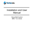
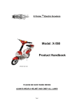
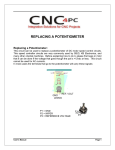
USER’S
MANUAL
C38 BREAKING CIRCUIT BOARD
Rev. 3
FEBRUARY, 2015
USER'S MANUAL
TABLE OF CONTENTS
Page #
1.0
FEATURES ..................................................................................................................... 1
2.0
SPECIFICATIONS .......................................................................................................... 1
3.0
WARNINGS .................................................................................................................... 1
4.0
BOARD DESCRIPTION .................................................................................................. 2
5.0
Tuning and installing the board (STEP BY STEP) ....................................................... 2
6.0
WIRING SAMPLE ........................................................................................................... 5
7.0
DIMENSIONS.................................................................................................................. 6
User’s Manual
Page i
1.0
FEATURES
•
Braking Circuit for switching mode power supply.
•
Prevents Back EMF.
•
Supports 24V, 36 and 48V Power Supplies.
•
Jumpers to select the Operating voltage.
•
Up to 12Amps.
•
Screw Terminal for driver power connection.
2.0
SPECIFICATIONS
Supported Power Supply
Supported Voltages
Logic supply voltage (VDC)
Maximum Supported Current
3.0
Switching mode
24V, 36V or 48V
5V and 12V
12Amp
WARNINGS
Electrical shock or serious physical injury could result due to
misuse Control BOX.
Disconnect power cables while installing the Control Box
Components.
Read and follow instructions on the manual.
User’s Manual
Page 1
4.0
BOARD DESCRIPTION
5.0
TUNING AND INSTALLING THE BOARD (STEP BY STEP)
Step 1. Turn ON the switching mode DC Power Supply.
Step 2. Using a multimeter, measure the power Supply output Voltage.
Step 3. Select the C38 operating DC voltage by using the selection jumpers.
24VDC_PS
User’s Manual
Page 2
36VDC_PS
48VDC_PS
Supported voltages are 24V, 36V and 48V. Be sure that the power supply provides one
of these voltages.
Step 4. Use the potentiometer in the Power supply to adjust the output to the minimum
output voltage.
Step 5. Connect the power supply to the C38 DC input voltage terminals.
User’s Manual
Page 3
Step6.
Note: This is a critical step because damage could be caused to the C38. Read carefully
this step before proceeding.
Increment the power supply output voltage until the dump indicator LED lights.
IMMEDIATELY turn OFF the power supply.
Step 7. Disconnect the power supply from the C38.
Step 8. Turn ON the power supply and measure the output voltage.
Step 9. Using the potentiometer in the Power supply, reduce in 0.5V the output voltage.
e.g. if the measured voltage in the step 8 was 48.3VDC, in this step the voltage should
be reduced to 47.8VDC.
Step 10. The C38 is calibrated and ready to be use.
Step 11. Turn OFF the power supply, Connect the power supply to the C38 DC input
voltage terminals and connect the drivers to the C38.
User’s Manual
Page 4
6.0
WIRING SAMPLE
User’s Manual
Page 5
7.0
DIMENSIONS
All dimensions are in millimeters.
Disclaimer:
Use caution. CNC machines can be dangerous machines. Neither DUNCAN USA, LLC
nor Arturo Duncan are liable for any accidents resulting from the improper use of these
devices. This board is not a fail-safe device and it should not be used in life support
systems or in other devices where its failure or possible erratic operation could cause
property damage, bodily injury or loss of life.
User’s Manual
Page 6