1
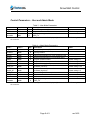
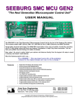
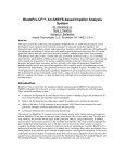
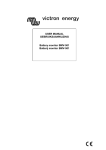
Installation and User
Manual
Snow Melt Control
SMC 1 to 3 Zone
Snow Melt Control
Table of Contents
Mounting ..........................................................................................................................3
Electrical ..........................................................................................................................3
Low Voltage and Sensors ................................................................................................3
Box Layout .......................................................................................................................5
Wiring Diagram ................................................................................................................6
Controller Basics ..............................................................................................................7
Controller Keypad ............................................................................................................8
USER MODE ...................................................................................................................8
ADMIN MODE..................................................................................................................8
Snow Melt Operation........................................................................................................8
Control Parameters – User and Admin Mode ..................................................................9
Page 2 of 9
rev 1403
Snow Melt Control
This document describes the installation of the Vortex Snow Melt Control as a stand alone
control connected to external pumps.
Mounting
The cabinet is 12x12x8 ½ inches plus a one inch top and bottom mounting flange. Mount
the control cabinet on a wall using suitable wall anchors. It must be mounted indoors, in a
dry location. The top centre hole may be used a temporary hanging hook until suitable
screws and anchors are used to fasten the four corners to the wall. The control will
operate normally with the cabinet mounted in any orientation (up, down, sideways) but the
control display is oriented for mounting in the up position.
Electrical
The control is rated for a maximum of 12amps total connected pumps. All pumps must be
120vac/1ph/60Hz. Unless otherwise stated on the rating label (240vac is available as
special order).
Connect power supply and pumps to the controller using suitable cable (i.e. BX) and
connectors through the available knockouts on the bottom of the cabinet.
Note that all side panels can be removed during installation.
Low Voltage and Sensors
All low voltage connections are found on the control box beside the controller. All
temperature sensors are 10K type 2 NTC thermistors. Wires may be extended with low
voltage (thermostat) wire.
Supply Sensor – Mount on the surface of the pipe supplying heated fluid to the snowmelt
loop. Cover with at least ½” of pipe insulation. Connect to Supply therm and Common.
Return Sensor -- Mount on the surface of the pipe returning the fluid from the snowmelt
loops. Cover with at least ½” of pipe insulation. Connect to Return therm and Common.
Outdoor Sensor – Mount outdoors, preferably on a wall above snow level and out of direct
sunlight (North wall). Connect to Outdoor therm and Common.
Boiler TT – dry contact/low voltage connection to activate a boiler whenever the snow melt
comes on.
Page 3 of 9
rev 1403
Snow Melt Control
Zone 1A (dry)
Zone 1B (dry)
Common
24vac
These four connections are for a typical 4-wire snow detector. For 3-wire, do not connect
zone 1B. Refer to snow sensor wiring diagram.
Page 4 of 9
rev 1403
Snow Melt Control
This document describes usage and operation of the controller for the Vortex Snow Melt
Control (SMC). It is recommended that the installing contractor read through this short
manual in order to become familiar with the correct system setup procedure, and to take
advantage of the various features available. The controller may be part of a pre-wired,
packaged system including pumps and heat exchangers or it may be a stand-alone control
with all pumps field wired. The controller has the capacity for up to 3 separate snow melt
zones.
Controller Basics
The controller can operate all snowmelt pumps as well as a dry contact TT to activate a
boiler. Through its LCD display and keypad, important system parameters may be
configured and operating conditions may be monitored.
When the controller keypad has not been pressed for a few minutes, the backlight will turn
off and the display may go blank. Simply press any one of the buttons to wake up the
controller. By default, the controller will display a short message describing the operating
status of the system. Table 1 provides a list of the different possible status messages and
their meaning. There are also a number of small icons that may appear around the edges
of the display according to the current operating status.
Table 2 below gives an
explanation of the different icons.
Table 1 - status messages
Meaning
Message
READY
IDLE ON
NORMAL
TooCOLD
TooWARM
FreezeX
No calls, but system is ready
No calls, pumps running in idle mode
At least one zone on and operating normally
Cold weather shutdown, too cold outside to run snowmelt
Warm weather shutdown, too warm outside to run snowmelt
Heat Exchanger is below freeze setting
Table 2 - display icons
Icon
Flame
Snowflake
Sun
Moon
Fan
Meaning
Injection pump on
Zone 1 call
Zone 2 call
Zone 3 call
Idle on
Page 7 of 9
rev 1403
Snow Melt Control
Controller Keypad
By using the option and setting keys, different parameters and their settings may be
displayed and modified. Use the option key to scroll through the available parameters,
and use the setting key to modify the parameter’s current setting (if available). By default,
the control will remain in ‘user’ mode, in which a limited selection of parameters may be
accessed. By entering ‘admin’ mode, additional parameters may be made available.
Please exercise caution while in ‘admin’ mode, as these settings are meant to be
accessed by the experienced user or installing contractor. A description of each of the
modes is found below.
USER MODE
This is the basic display and operating mode, in which only a limited selection of
parameters may be accessed and modified. Refer to Table 3 for description of each item
displayed.
ADMIN MODE
This is the advanced display and configuration mode. It is intended only for the properly
trained contractor. To enter ‘admin’ mode, press any button to illuminate the display
backlight, then press and hold the two option buttons at the same time (‘user’ will be
displayed at first, hold until ‘admin’ is displayed). You can now scroll through the display
items by using the lower two option buttons, and adjust certain values using the upper two
setting buttons. To return the control to ‘user’ mode simply wait a few minutes or press
and hold both option buttons. Use Table 4 as a quick reference on the items available in
this mode. Detailed descriptions on important parameters are found below.
Snow Melt Operation
There following parameters may be useful in system commissioning and troubleshooting.
IDLE_SP (default is 2°C) – The return fluid setting when idle mode is on. Typcially slightly
above or below freezing.
Supp_SP (default is 30°C) – The supply fluid setting when in snow melt or idle mode.
CWS_SP (default is -20°C) – Below this outdoor temperature it is too cold for the
snowmelt to operate.
WWS_SP (default is 5°C) – Above this outdoor temperature it is too warm for snowmelt to
operate.
FRZ_SP (default is 4°C) – Below this heat exchanger temperature, the snow melt will not
operate.
Page 8 of 9
rev 1403
Snow Melt Control
Control Parameters – User and Admin Mode
Table 3 - User Mode Parameters
Line 1
Outdoor
SMC3
Line 2
####
####
Set.*
D
D
Description
Notes
Outdoor Temperature (C)
Program revision number
Default setting is 1
Displays operating condition as text based on
SnowMlt
####
D
DISP_FX
* Note: “D” in the set column indicates this parameter is for display only, and cannot be modified using
the controller.
Table 4 – Admin Mode Parameters
Line 1
Outdoor
Line 2
####
Set.*
D
Description
Notes
Outdoor Temperature (C)
Heat Exchanger surface temperature used for
HeatExc
####
D
freeze protection
Return
####
D
Return fluid temperature (C) from snowmelt loops
Supply
####
D
Supply fluid temperature (C) to snowmelt loops
SMC3
####
D
Program revision number
Default setting is 1
IDLE_SP
####
Setpoint fluid return temperature for idle mode
Default setting is 2
Supp_SP
####
Setpoint fluid supply temperature
Default setting is 30
Setpoint outdoor temperature for cold weather
CWS_SP
####
shutdown (low limit)
Default setting is -20
Setpoint outdoor temperature for warm weather
WWS_SP
####
shutdown (high limit)
Default setting is 5
FRZ_SP
####
Heat exchanger freeze setpoint
Default setting is 4
IDLE_ON
####
Enables idle function
Modbus
####
Modbus address
Default setting is 180
Displays operating condition as text based on
SnowMlt
####
D
DISP_FX
* Note: “D” in the set column indicates this parameter is for display only, and cannot be modified using
the controller.
Page 9 of 9
rev 1403