1
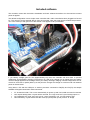
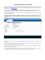
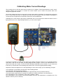
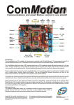
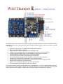
Wild Thumper
Robot Controller
The Wild Thumper robot controller is an AVR / Arduino compatible controller that offers enthusiast the ability
to get their robot up and running quickly an easily. Although relatively small in size this controller is packed
with features:
•
•
•
•
•
•
•
•
•
•
•
•
•
Dual 15A continuous FET “H” bridges with individual fuse protection.
Current sensing for both “H” bridges.
Blown fuse can be detected by processor and indication LED.
7 digital I/O pins terminated with 3 pin male header allowing servos to plug in directly.
5 analog inputs terminated with 3 pin male headers to supply power for sensors.
5A LDO regulator to supply power for logic, servos and sensors.
2A DC power socket for testing / programming and recharging.
SLA, NiCd and NiMh batteries can be charged via onboard 2A current regulator.
Processor can monitor battery voltage and control recharge circuitry.
Communicates via USB, TTL serial, and I2C. Can also work with RC and analog inputs.
Atmega 168 processor with 16K flash memory.
Arduino / AVR compatibility. Program via USB or ISP interface.
Comes preloaded with Arduino boot loader and software.
This is a low voltage controller and was designed to be powered by a 7.2V sub C battery pack as commonly
found in RC cars. Higher battery voltages can be used (maximum 18V DC) but will reduce the maximum
current output of the 5V regulator. A small CPU fan may be mounted on the heat sink if required.
Included software
The controller comes with the Arduino bootloader and basic software that allows it to be used the moment
power is applied.
The default configuration is as a simple motor controller with a radio controlled receiver plugged into D0 and
D1. The receiver can be powered directly from the controller. Note the signal wire is towards the processor,
+5V is the center pin and ground is to the outside. This applies to all 3 pin headers.
If you battery voltage gets too low (approximately 6V) then the controller will shut down to prevent
malfunction and the battery charging circuit will turn on. With a DC voltage of 3-6V higher than your battery
nominal voltage applied to the recharge socket your battery will begin charging until the voltage levels out for
more than 5 minutes or peaks (delta V) at this point the charger will change to a trickle mode until external
power is disconnected.
Using either a PC and the USB port or another processor connected to D0(RX) and D1(TX) the sample
software will support these basic serial commands:
•
•
•
•
“FL” flushes the buffer. This occurs automatically on power up and if an invalid command is received.
“AN” request analog data. 10 bytes will be received, The “high” and “low” byte of analog inputs 1-5.
“SV” followed by the “high” and “low” byte of 7 servo positions in uS. 14 bytes must be sent.
“HB” followed by 4 bytes of data sets the mode (0-2) and power (0-255) of each “H” bridge.
Using the Arduino environment
The included software also supports basic serial commands for controlling the motors, servos and reading
analog inputs. These features can be accessed using the Arduino 0018 or later programming environment
freely available from http://arduino.cc/
The controller cannot be powered directly from the USB port. The controller must be powered from batteries
or a DC supply (6-12V). If using the DC socket then current will be limited via the recharge circuit.
With the controller powered and connected to a PC via USB cable the program can be easily re-configured
or edited to suit your needs.
Download and install the Arduino environment. Then open the “Wild_Thumper_Controller.pde” file. To edit
the supplied software or upload new software with the Arduino environment you must first select the correct
serial port and board type from the Tools tab at the top of the window. Choose the “Nano w/ ATmega 168” as
your board.
You will see three tabs at the top of the program labelled “Wild_Thumper_Controller”, “Constants.h” and
“Iopins.h”.
The “Wild_Thumper_Controller” tab contains the main program. This can be changed to suit your needs. The
controller can be the brains as well as the brawn of a robot.
The “Constants.h” tab stores values such as communications mode, baud rate, minimum battery voltage,
maximum allowable current draw etc.
The “I/Opins.h” tab tells the program which of the processors I/O pins are used for what function. Take care
when modifying the contents of this tab as many functions are “hard wired” on the PCB.
Configuring the controller
With a few simple modifications to the “Constants.h” tab your controller can be adjusted to accept serial
communications, charge different batteries and protect different motors from overload.
For example, changing “Cmode” to a value of 1 will change the communications mode to Serial. Change
“Brate” to your preferred baud rate: 300, 1200, 2400, 9600, 14400, 19200, 28800, 38400, 57600 or 115200,
The supplied software is programmed for a 7.2V NiCd or NiMh Sub C battery pack and will need changing if
other batteries are used. Do not use LiPo or Li-ion batteries with this charger! If you are not sure what
batteries you are using then do not use the recharge feature on this board.
The battery monitoring circuit will report a value of approximately 65 for every volt measured across the
battery. The “lowvolt” value represents the voltage at which the controller shuts down to recharge so 410 / 65
gives a cutoff point of approximately 6.3V. The “batvolt” value is the nominal battery voltage. The program
uses this to determine the minimum voltage at which delta V can occur.
As an alternative, 6x NiMh or NiCd “AA” (UM-3) batteries could be used. Although the Charging circuit is
designed to deliver 2A of current it is not recommended for these smaller batteries and can be reduced by
reducing the voltage applied to the recharge socket.
Calibrating Motor Current Readings
The controller uses 2 15A slow blow fuses to protect the “H” bridges. These fuses double as current “shunt”
resistors allowing the processor to monitor the current drawn by the motors and protect them from
dangerously high stall currents.
The sample software will shut a motor down if a safe current level is exceeded. This should also protect the
fuse. If a fuse does blow then an indicator LED near the fuse will light up and the software will register a
current level much higher than normal stall currents even at low PWM levels.
Calibrating the current sensors will require a Multimeter with a 10A range and a stable test load such as a
light globe from a car or a high wattage resistor e.g. 10 ohm, 5W or higher.
Connect the controller to a battery or DC supply by the battery terminals. Connect to your computer with the
USB cable. Load and run the “Wild_Thumper_Diagnostic.pde” program. Click on the “Serial Monitor” icon
and set the baud rate to 9600. You will see the load being measured by the processor. If you remove the
fuses then you will see the current readings jump above 700. This is the highest possible reading.
Replace the fuses and adjust VR1 or VR2 depending on which motor output you are calibrating. Example:
Your multimeter is connected to the left motor and is reading 940mA.
You adjust VR1 until the processor reads 47.
The left motor is now calibrated with a resolution of approximately 20mA (47x20mA=940mA).
Your motors have a stall current of 12Amps. To protect you motors you decide 11A is the safe limit.
Set “Leftmaxamps” in the “Constants.h” tab to 550 (11000mA / 20mA).
Set “overloadtime” to the number of mS required before the motor can restart after an overload occurs. The
default is 100mS (1/10 of a second).