1
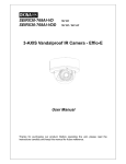
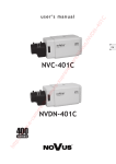
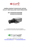
Installation Manual MManualManual Set up and user manual for the VVRD28V12CM960H / U VVRD28V12DN960H / U VVRD28V12DNLED960H / U Cameras i Before You Begin Read these instructions before installing or operating this product. Note: This installation should be made by a qualified service person and should conform to local codes. This manual provides installation and operation information. To use this document, you must have the following minimum qualifications: A basic knowledge of CCTV systems and components A basic knowledge of electrical wiring and low-voltage electrical connections Intended use Only use this product for its designated purpose; refer to the product specification and user documentation. Customer Support For assistance in installing, operating, maintaining and troubleshooting this product refer to this document and any other documentation provided. If you still have questions, please contact Norbain Technical Support and Sales: Norbain SD Ltd, 210 Wharfedale Road, IQ Winnersh, Wokingham, Berkshire RG41 5TP, England. UK +44 (0) 118 912 5000 Note: You should be at the equipment and ready with details before calling Technical Support. Conventions Used in this Manual Boldface or button icons highlight command entries. The following WARNING, CAUTION and Note statements identify potential hazards that can occur if the equipment is not handled properly: * WARNING: Improper use of this equipment can cause severe bodily injury or equipment damage. ** Caution: Improper use of this equipment can cause equipment damage. Note: Notes contain important information about a product or procedure. ii This apparatus is manufactured to comply with the radio interference. A Declaration of Conformity in accordance with the following EU standards has been made. The manufacturer declares that the product supplied with this document is compliant the provisions of the EMC Directive 2004/108/EC, the CE Marking Directive 93/68 EEC and all associated amendments. All lead-free products offered by the company comply with the requirements of the European law on the Restriction of Hazardous Substances (RoHS) directive: 2011/65/EU, which means our manufacture processes and products are strictly “lead-free” and without the hazardous substances cited in the directive. The crossed-out wheeled bin mark symbolizes that within the European Union the product must be collected separately at the product end-of-life. This applies to your product and any peripherals marked with this symbol. Do not dispose of these products as unsorted municipal waste. * This symbol indicates electrical warnings and cautions. ** This symbol indicates general warnings and cautions. NORBAIN SD LTD reserves the right to make changes to the product and specification of the product from time to time without prior notice. WARNINGS AND CAUTIONS: To reduce the risk of fire or electric shock, do not insert any metallic objects through the ventilation grills or other openings on the equipment. CAUTION CAUTION RISK OF ELECTRIC SHOCK DO NOT OPEN WARNING: TO REDUCE THE RISK OF ELECTRIC SHOCK, DO NOT REMOVE COVER (OR BACK). NO USER-SERVICABLE PARTS INSIDE. REFER SERVICING TO QUALIFIED SERVICE PERSONNEL. iii IMPORTANT SAFEGUARDS 1. READ AND RETAIN INSTRUCTIONS Read the instruction manual before operating the equipment. Retain the manual for future reference. 2. CLEANING Turn the unit off and unplug from the power outlet before cleaning. Use a damp cloth for cleaning. Do not use harsh cleansers or aerosol cleaners. 3. ATTACHMENTS Do not use attachments unless recommended by manufactured as they may affect the functionality of the unit and result in the risk of fire, electric shock or injury. 4. MOISTURE Do not use equipment near water or other liquids. 5. ACCESSORIES Equipment should be installed in a safe, stable location. Any wall or shelf mounting accessory equipment should be installed using the manufacture's Instructions. Care should be used when moving heavy equipment. Quick stops, excessive force, and uneven surfaces may cause the equipment to fall causing serious injury to persons and objects. 6. VENTILATION Openings in the equipment, if any, are provided for ventilation to ensure reliable operation of the unit and to protect if from overheating. These openings must not be blocked or covered 7. POWER SOURCES The equipment should be operated only from the type of power source indicated on the marking label. If you are not sure of the type of power supplied at the installation location, contact your dealer. For equipment designed to operate from battery power, refer to the operating instructions. 8. GROUNDING OR POLARIZATION Equipment that is powered through a polarized plug (a plug with one blade wider than the other) will fit into the power outlet only one way. This is a safety feature. If you are unable to insert the plug fully into the outlet, try reversing the plug. Do not defeat the safety purpose of the polarized plug. Alternate Warning: If the equipment is powered through a three-way groundingtype plug, a plug having a third (grounding) pin, the plug will only fit into a groundingtype power outlet. This is a safety feature. Do not defeat the safety purpose of the grounding-type plug. If your outlet does not have the grounding plug receptacle, contact your local electrician. 9. CORD AND CABLE PROTECTION Route power cords and cables in such a manner to protect them from damage by being walked on or pinched by items places upon or against them. 10. LIGHTNING For protection of the equipment during a lightning storm or when it is left unattended and unused for long periods of time, unplug the unit from the wall outlet. Disconnect any antennas or cable systems that may be connected to the equipment. This will prevent damage to the equipment due to Lightning or power-line surges. 11. OVERLOADING Do not overload wall outlets and extension cords as this can result in a risk of fire or electric shock. iv 12. SERVICING Do not attempt to service the video monitor or equipment yourself as opening or removing covers may expose you to dangerous voltage or other hazards. Refer all servicing to qualified service personnel. 13. DAMAGE REQUIRING SERVICE Unplug the equipment from the wall outlet and refer servicing to qualified service personnel under the Following conditions: A. When the power supply cord or the plug has been damaged. B. If liquid has spilled or objects have fallen into the Unit. C. If the equipment has been exposed to water or other liquids. D. If the equipment does not operate normally by following the operating instructions, adjust those controls that are covered by the operating instructions as Improper adjustment for other controls may result in damage to the unit. E. If the equipment has been dropped or the casing is damaged. F. When the equipment exhibits a distinct change in performance. 14. REPLACEMENT PARTS When replacement parts are required, be sure the service technician uses replacement parts specified by the manufacturer or that have the same characteristics as the original part. Unauthorized substitutions may result in fire, electric shock, or other hazards. 15. SAFETY CHECK Upon completion of any service or repairs to the equipment, ask the service technician to perform safety checks to verify that the equipment is in proper operating condition. 16. FIELD INSTALLATION The installation of equipment should be made by a qualified service person and should conform to all local codes. 17. CAUTION THESE SERVICING INSTRUCTIONS ARE FOR USE BY QUALIFIED SERVICE PERSONNEL ONLY. TO REDUCE THE RISK OF ELECTRIC SHOCK DO NOT PERFORM ANY SERVICING OTHER THAN THAT CONTAINED IN THE OPERATING INSTRUCTIONS UNLESS YOU ARE QUALIFIED TO DO SO. 18. Use certified/Listed Class 2 power source only. CE COMPLIANCE STATEMENT WARNING This is a Class A product. In a domestic environment this product may cause radio interference in which case the user may be required to take adequate measures. v TABLE OF CONTENTS INTRODUCTION --------------------------------------------------------------------------------------- 7 CONTENTS OF PACKAGE ------------------------------------------------------------------------- 8 BASIC INSTALLATION ------------------------------------------------------------------------------- 8 TACT SWITCH OPERATION / SERVICE JACK ----------------------------------------------- 9 OSD MENU STRUCTURE -------------------------------------------------------------------------- 10 DEAD PIXEL CORRECTION------------------------------------------------------------------------ 19 LENS ADJUSTMENT --------------------------------------------------------------------------------- 17 DIMENSIONS ------------------------------------------------------------------------------------------- 18 SPECIFICATIONS ------------------------------------------------------------------------------------- 19 vi INTRODUCTION Camera Model Features: ● ● ● ● ● ● ● ● ● ● ● ● ● ● ● ● ● ● ● ● ● ● ● ● 1/3" Sony Super HAD II CCD (960H) with Effio E II DSP 700TVL Colour & Monochrome resolutions 2.8-12mm (F1.4-360) 2MP varifocal lens 0.25Lux (Colour) @ F1.4 sensitivity (CM) 0.25Lux (Colour) / 0.02Lux (Monochrome) @ F1.4 sensitivity (DN) 0.25Lux (Colour) / 0Lux (Mono) @ F1.4 sensitivity (DNLED Model – IR LED’s On) Auto electronic shutter (1/50 to 1/10,000) and manual electronic shutter modes Day & Night – Auto, Colour, B/W (Monochrome) 20m IR coverage from 16 x 850nm LEDs (DNLED model only) OSD - On Screen Display (via tact switch) ATR (Adaptive Tone Reproduction) AGC (Auto Gain Control) NR function (2DNR - Digital Noise Reduction) Auto and manual white balance modes BLC (Back Light Compensation) HLC (High Light Compensation - PWI) 8 Privacy zones (colour or mosaic) 4 Motion detection zones Functions (Mirror, Brightness, Sharpness, Hue, Contrast, Gain) Multi language support: English, German, French, Russian, Portuguese, Spanish Integral passive UTP balun (U Models) Test Monitor Output (Service Jack) 12/24V operation IP66 Vandal resistant casing (Built to IK10) Use Certified Listed Class 2 power source only 7 CONTENTS OF PACKAGE Installation of the camera must be performed by qualified service personnel in accordance with all local and national electrical and mechanical codes. Carefully remove the colour camera and its accessories from the carton and verify that they were not damaged in shipment. The content of the package includes: 1. Camera 2. Fixings 3. Instruction manual 4. Template sheet 5. DC Jack BASIC INSTALLATION CAUTION: When installing the camera outdoors, the following instructions must be followed closely. 1. Loosen the four Torx screws on the housing cover. These are captive so there is no need to remove completely. 2. Use the mounting template as a drilling guide to ensure correct positioning of the screws. 3. Drill 4 holes into the mounting template. Insert the screw raw plugs (anchors) and attach the housing using the 4 x M6 Torx screws. NOTES: If the 2.1mm jack adaptor is not used then please ensure the correct polarity is observed when 12VDC is being used. The terminals are colour coded to assist: Red = 12VDC / Black = 0V If using the UTP (U) models, please note that you cannot use the BNC output at the same time. If the camera is being installed externally, please ensure the side ¾” NPT thread is sealed with Teflon tape or suitable sealant. There are 2 photocells on the LED array in DNLED models and the cap is pre-fitted to one of these. To reduce any hunting effect, please place the cover over the photocell that is closer to being angled/located inside the housing. 8 Adjusting Camera Module TACT SWITCH OPERATION The tact switch allows both navigation and changes to the OSD Menu. To enter into the OSD menu push centrally on the joystick and navigate using the up, down, left and right actions. If there is an arrow to the right of the menu function, this denotes that there is an accessible sub menu function. The white plug to the left is the service jack to allow setup of the camera without having to remove the main video cable (the service cable is available separately) 9 OSD MENU STRUCTURE SETUP MENU (page 1) LANGUAGE LENS SHUTTER/AGC WHITE BAL BACKLIGHT PICT ADJUST ATR LENS SHUTTER/AGC AUTO IRIS MANUAL AUTO MANUAL RETURN RETURN NEXT (page2) EXIT SAVE ALL WHITE BALANCE BACKLIGHT ATW PUSH USER 1 USER 2 ANTI CR MANUAL PUSH LOCK BLC HLC RETURN RETURN PICTURE ADJUST ATR MOTION DET MIRROR BRIGHTNESS CONTRAST SHARPNESS HUE GAIN LUMINANCE CONTRAST DETECT SENSE BLOCK DISP MONITOR AREA AREA SELECT RETURN RETURN RETURN 10 SETUP MENU (page 2) MOTION DET PRIVACY DAY/NIGHT NR CAMERA ID CAMERA RESET PRIVACY DAY/NIGHT AREA SEL COLOUR TRANSP MOSAIC AUTO COLOUR B/W RETURN RETURN BACK (page 1) EXIT SAVE ALL NR CAMERA ID LANGUAGE NR MODE Y LEVEL C LEVEL (titling) ENGLISH GERMAN FRENCH RUSSIAN PORTUGUESE SPANISH RETURN RETURN CAMERA RESET RETURN (return the camera to factory defaults) RETURN RETURN RETURN RETURN RETURN 11 LENS Manual Manual lens only Auto Type: DC, Video (Sets the type of lens and whilst Video is selectable, it is not supported on this model) Mode: Open, Close, Auto (Sets the type of control applied over the mechanical iris) Speed: 0 - 255 (increments of 1) Sets the convergence speed of the mechanical iris. SHUTTER / AGC Auto High Luminance Mode: Shut, Shut+Auto Iris, Auto Iris (Shut can only be selected if the lens is set to Manual mode) Brightness: 0 to 255 (increments of 1) (Adjusts the brightness of the image) Low Luminance Mode: AGC, Off (Auto Gain Control on or off) Brightness: x0.25, x0.50, x0.75, x1.00 (Sets the brightness applied in low light conditions) Manual Mode: Shut+AGC Shutter: 1/50, 1/120, 1/250, 1/500, 1/1000, 1/2000, 1/4000, 1/10000 (Select the shutter speed) AGC: 6, 12, 18, 24, 30, 36, 42, 44.8dB (Sets the AGC gain applied [dB] for manual exposure) 12 WHITE BAL Modes: ATW, Push, User1, User2, Anti CR, Manual, Pushlock (Adjusts the white balance to suit area being viewed) ATW (Auto Trace White balance) Speed: 0 to 255 (increments of 1) (Adjusts the pull in speed of ATW) Delay Cnt: 0 to 255 (increments of 1) (Sets the time-based hysteresis of ATW) ATW Frame: x0.5, x1.5, x2 (Sets the pull in frame magnification) Environment: Indoor, Outdoor (Preset for either indoor or outdoor applications of the ATW) Push: Sets the mean of the Auto White Balance (AWB) of the area viewed User 1 & 2: Both User1 & 2 can be individually set up for specific applications. B-Gain: 0 to 255 (increments of 1) R-Gain: 0 to 255 (increments of 1) Anti CR: When shut+auto iris mode used, this setting can reduce, but may not eliminate colour roll caused by fluorescent lighting. Manual: A single scale, simultaneous adjustment of the B and R gain values Level: 24 to 97 (increments of 1) (The lower the number, the higher content of Red, the higher the number the higher content of Blue in the image) Pushlock: Sets the white balance based on the lighting level at the camera at that time (Best used when there is no change in the illumination level) BACKLIGHT Modes: Off, BLC, HLC. BLC: Globally applies non adjustable BLC (Back Light Compensation) to the image HLC: Globally applies non adjustable HLC (High Light Compensation – Peak White Inversion) to the image 13 PICT ADJUST Mirror: Off, on (horizontally inverts image). Brightness: 0 – 255 (increments of 1) Contrast: 0 – 255 (increments of 1) Sharpness: 0 – 255 (increments of 1) Hue: 0 – 255 (increments of 1) Gain: 0 – 255 (increments of 1) (in all of the above, the smaller the number, the darker or lower the setting that is applied) ATR ATR (Adaptive Tone Reproduction) allows adjustment of the image to assist with widely contrasting scenes of view. Luminance: Low, Mid, High (Sets the luminance applied) Contrast: Low, Midlow, Mid, Midhigh, High) (Sets the contrast enhancement) MOTION DET MOTION DETECTION: allows upto 4 areas of motion to be set up (note there is no output) Detect Sense: 0 – 127 (increments of 1) (Sets the motion detection sensitivity, 0=low sensitivity, 127=high sensitivity) Block Disp: Off, On, Enable (Applies a motion block trace in the user selected area. To define the area, select ‘Enable’ and push centrally on the joystick. Use the Joystick to navigate to the blocks you want to Disable and not include in motion trace. To return to the menu, push and hold central joystick for 2secs and release) Motion Area: Off, On (Enables/disables the motion detection) Area Sel: 1 - 4 (Selects the motion detection area) Top: 0 – 244 (increments of 1) 0=top, 244=bottom Bottom: 0 – 244 (increments of 1) 0=top, 244=bottom Left: 0 – 474 (increments of 1) 0=left, 474=right Right: 0 – 474 (increments of 1) 0=left, 474=right 14 PRIVACY PRIVACY: allows upto 8 masks to be applied to the image (note that if motion area in motion det menu is set to ‘on’, this reduces to 4 privacy zones) Area Sel: 1 - 8 (Selects the motion detection area) Top: 0 – 244 (increments of 1) 0=top, 244=bottom Bottom: 0 – 244 (increments of 1) 0=top, 244=bottom Left: 0 – 474 (increments of 1) 0=left, 474=right Right: 0 – 474 (increments of 1) 0=left, 474=right Colour: 1 – 8 (Choose from the following colours for the privacy zones - red, green, blue, lime, cyan, magenta, white, black) Transp: 0.00, 0.50, 0.75, 1.00 (Sets the transparency of the privacy zone area) Mosaic: Off, On (when mosaic is set to On, all programmed privacy zones switch to a non adjustable mosaic/tile distortion effect. For full mosaic, Transp needs to be set to 0.00) DAY / NIGHT Day / Night: make changes to the camera operation Modes: Auto, colour, B/W, Ext1, Ext2 Auto (auto switching between colour& monochrome on CM & DN models) Burst: Off, on (Allows the colour burst signal in monochrome to be removed if required) Delay Cnt: 0 – 255 seconds (increments of 1) Sets the hysteresis time before switching between colour/mono & mono/colour, to reduce the ‘hunting’ effect Day -> Night: 0 – 255 (increments of 1) Sets the threshold for switching from day to night operation (The higher the number, the darker it needs to be before switching to B&W) Night -> Day: 0 – 255 (increments of 1) Sets the threshold for switching from night to day operation (The higher the number, the brighter it needs to be before switching to colour) Colour: Colour only operation 15 B/W: Monochrome only operation Burst: Off, On (Allows the colour burst signal in monochrome to be removed if required) IR Optimizer: Off, On (if On, then Mode & Level are adjustable) Mode: Auto, Centre Level: 0 – 31 (increments of 1) Ext 1: Switches to permanent mono mode and reflects the setting in B/W mode Ext2 (auto switching between colour& monochrome on DNLED models) Camera switching operation is determined by the photocells – there is no programmable delay time or switching level. NR (2DNR) Digital noise reduction is used to remove ‘noise’ from the image in low light conditions when AGC is applied. NR mode : Off, Y, C, Y/C (Sets the 2D NR filter mode) Y Level: 0 – 15 (increments of 1) Sets the Y filter (Luminance) strength. C Level: 0 – 15 (increments of 1) Sets the C filter (Chrominance) strength. CAMERA ID Sets the camera ID to ON or OFF. A title of 26 characters per line can be applied. Use the joystick to navigate the cursor. Pushing centrally on the joystick will allow selection of that character. The arrows at the bottom allow you to move the cursor without changing the character. CHR1 Allows you to edit line 1 CHR2 Allows you to edit line 2 CLR Inserts a space POS Allows you adjust the location of the camera ID title display. 16 SYNC This is fixed within the camera and non-adjustable. LANGUAGE LANGUAGE select between: English (EN), German (DE), French (FR), Russian (RU), Portuguese (PT) & Spanish (ES). CAMERA RESET CAMERA RESET - Returns the camera to the factory default settings. EXIT / SAVE ALL EXIT – Exits the menu and does not save changes made if the power is recycled to camera. SAVE ALL - Saves all the changes made in the menu. 17 DEAD PIXEL CORRECTION It is perfectly normal for a camera CCD to have what is known as ‘dead’, ‘hot’ or ‘white’ pixels, develop over time and on occasion and these can be noticeable on the viewed image. These can be masked easily without affecting the quality of the image, with the DPC function. To access this, push and hold the joystick LEFT for 5 seconds, then cover the lens and push ENTER (central push on the OSD tact switch), then follow the instructions on the screen. Please note: If there are over 65 dead pixels the camera will not run the DPC function 0 If the temperature is over 70 C this function will not run. LENS ADJUSTMENT Zoom ring: Adjust setting from Tele (T) to Wide (W) field of View. Focus ring: Adjust lens focus from near (N) to infinity ( ). Focus ring 2.8 to 12mm Image Size Focal Length Aperture Ratio Zoom ring 1/2.7’’ CCD 2.8-12mm 5% 1 : 1.4 5% HORIZONTAL Angular Field of View 2.8mm: 81.2 12mm: 22.6 18 DIMENSIONS 19 SPECIFICATIONS Model Resolution Image sensor DSP Total pixels Effective pixels Scanning Syst. Scanning Freq. Sync. system Video output S/N Ratio Lens Min. illumination General Function IR LEDs IR Illumination OSD Control Electronic Shutter ATR Backlight Day / Night White Bal. Motion Det. Privacy AGC Exposure NR (2DNR) Mirror Brightness Contrast Sharpness Hue Gain Mirror Title Language Power Connections/other Consumption Power input Video output Operating Temp. Storage Temp. Environmental Dims. (net) Dims. (gross) Weight VVRD28V12-960H DN CM DNLED 700TVL (colour and monochrome) 1/3″ SONY Super HAD (960H) Sony Effio E II 1020(H) x 596(V) 976(H) x 582(V) 2:1 Interlace PAL: 15.625KHz(H) x 50Hz(V) Internal 1.0Vp-p (75Ω, composite) 50dB (AGC off) f2.8 - 12mm Varifocal (F1.4 - 360) Colour 0.25Lux Mono 0.02Lux @F1.4 Colour 0.25Lux @ F1.4 N/A N/A Colour 0.25Lux Mono 0.02Lux@ F1.4 (0Lux IR LEDS on) 16 @ 850nm 20m Tactile switch Auto or Manual (1/50 to 1/10,000 sec) Off, Luminance (L , M, H), Contrast (L, LM, M, MH, H) Off, BLC, HLC (PWI) Auto, Colour, B/W (with IR optimizer), Ext1, Ext2 ATW, Push (AWB), User1, User2, Anti CR, Manual, Pushlock 4 areas 8 zones with 8 selectable colours or mosaic Off, On Auto Iris, Shut+Auto Iris Off, Y, C, Y/C Off, On 0 - 255 0 - 255 0 - 255 0 - 255 0 - 255 Off, On Off, On (2 x 26 characters) EN / DE / FR / RU / PT / ES 12VDC (-10 to +15%), 24VAC (+/-10%) 2W, 170mA @12VDC 3.6W, 300mA @12VDC 3W, 125mA @ 24VAC 4.1W, 170mA @24VDC 2-pin terminal block with 2.1mm jack adapter BNC connector, Spot Out -10 to 50°C -20 to 50°C IP66 & Built to IK10 (EN62262) 144 (Φ) x 94.5 (H) mm 155 (H) x 170 (W) x 170 (D) mm 650g (net) 910g (gross) 20 Model Resolution Image sensor DSP Total pixels Effective pixels Scanning Syst. Scanning Freq. Sync. system Video output S/N Ratio Lens Min. illumination General Function IR LEDs IR Illumination OSD Control Electronic Shutter ATR Backlight Day / Night White Bal. Motion Det. Privacy AGC Exposure NR (2DNR) Mirror Brightness Contrast Sharpness Hue Gain Mirror Title Language Power Consumption Connections/other Power / UTP input Video output Operating Temp. Storage Temp. Environmental Dims. (net) Dims. (gross) Weight (net) VVRD28V12-960HU DN CM DNLED 700TVL (colour and monochrome) 1/3″ SONY Super HAD (960H) Sony Effio E II 1020(H) x 596(V) 976(H) x 582(V) 2:1 Interlace PAL: 15.625KHz(H) x 50Hz(V) Internal 1.0Vp-p (75Ω, composite) & Passive UTP (100 Ω) 50dB (AGC off) f2.8 - 12mm Varifocal (F1.4 - 360) Colour 0.25Lux Colour 0.25Lux Colour 0.25Lux Mono 0.02Lux Mono 0.02Lux@ F1.4 @ F1.4 @F1.4 (0Lux IR LEDS on) N/A 16 @ 850nm N/A 20m Tactile switch Auto or Manual (1/50 to 1/10,000 sec) Off, Luminance (L , M, H), Contrast (L, LM, M, MH, H) Off, BLC, HLC (PWI) Auto, Colour, B/W (with IR optimizer), Ext1, Ext2 ATW, Push (AWB), User1, User2, Anti CR, Manual, Pushlock 4 areas 8 zones with 8 selectable colours or mosaic Off, On Auto Iris, Shut+Auto Iris Off, Y, C, Y/C Off, On 0 - 255 0 - 255 0 - 255 0 - 255 0 - 255 Off, On Off, On (2 x 26 characters) EN / DE / FR / RU / PT / ES 12VDC (-10 to +15%), 24VAC (+/-10%) 2W, 170mA @12VDC 3.6W, 300mA @12VDC 3W, 125mA @ 24VAC 4.1W, 170mA @24VDC 2-pin terminal block with 2.1mm jack adapter / UTP with 2 pin screw down terminals BNC connector, Spot Out -10 to 50°C -20 to 50°C IP66 & Built to IK10 (EN62262) 144 (Φ) x 94.5 (H) mm 155 (H) x 170 (W) x 170 (D) mm 650g (net) 910g (gross) 21 22 VVRD960H_U Manual / V1.0 / 2013-02-22 (subject to change without notice) 23