1
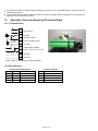
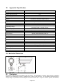
Installation Manual
MManualManual
Set up and user manual for the
VID-W22L050
Medium-Range Volumetric Infra-Red Detector
A Detector for Outdoor Perimeter Protection
Page 1 of 10
Table of Contents
Page
1
2
3
4
5
6
7
8
9
10
11
12
13
14
15
16
17
18
19
20
21
22
23
Introduction ..................................................................................................................................... 3
Features ........................................................................................................................................... 3
Mounting and Installation ............................................................................................................... 3
Connecting the VID-W22L050 ........................................................................................................ 3
Alarm Signalling.............................................................................................................................. 3
Field of View .................................................................................................................................... 3
Alignment ........................................................................................................................................ 3
Sensitivity Settings ......................................................................................................................... 4
Adaptive Threshold Discrimination (ATD) .................................................................................... 5
Pulse Count ..................................................................................................................................... 5
Anti-Vandal Function (AVF)............................................................................................................ 5
LED .................................................................................................................................................. 6
Alarm Time ...................................................................................................................................... 6
Internal Temperature Compensation ............................................................................................. 7
Accessories ..................................................................................................................................... 7
Maintenance .................................................................................................................................... 7
General Comment on the VID-W22L050 ........................................................................................ 7
Appendix Electronic Board and Terminal Block ........................................................................... 8
Appendix Specification .................................................................................................................. 9
Disclaimer........................................................................................................................................ 9
General Warning ........................................................................................................................... 10
Liability .......................................................................................................................................... 10
Warranty and Service ................................................................................................................... 10
Page 2 of 10
1
Introduction
The VID-W22L050 is a highly sensitive Passive Infra-Red detector designed for detection outdoors with a wide angle,
volumetric differential field of view. It incorporates microprocessor-controlled signal processing including signal shape
analysis, adaptive threshold level by feedback of environmental effects, temperature compensation and rejection of
disturbance signals.
Sensitivity adjustments are done with DIP-Switches for each individual unit in function of the required detection range in
order to adapt to the specific needs of an installation.
2
Features
Multi zone volumetric detector with creep zones
2.5 - 4 m (8-13ft) mounting height
Advanced tamper detection
Low power consumption – ideal for wireless and solar applications
Wide power supply range
Integrated Bracket for Wall Mounting
3
Mounting and Installation
The mounting structure should be sold enough to resist significant movement in windy conditions. Movement of the VIDW22L050 caused by vibrations or other movements will result in changing fields of view covered by the VID-W22L050
and could cause erratic signals. These unwanted signals may lead to an increase in the alarm threshold level which
reduces the detection probability or in certain cases can lead to unwanted alarms.
The stainless steel bracket is ideally suited for wall mounting. For pole mounting the VID-PA is available (the pole mount
bracket comes with two strap bands for poles with diameters of 4 – 16cm). For further information please refer to section
15.
It is very important that the cover of the detector is tightened securely. Tighten the two screws to the point where it
cannot be tightened further with reasonable force. There should be less than 1mm gap between the cover and the
bottom part of the housing.
The detectors are fitted with two M16 cable entry points. The nut on the cable entry assembly should be tightened to
clamp the cable in place. If the cable diameter is too small to be held properly, insulation tape should be wound around
the cable to increase the outside diameter to a suitable size.
4
Connecting the VID-W22L050
For the definition of the electronic board and terminal block see appendix 18.1.
5
Alarm Signalling
There are two types of alarm outputs on the VID-W22L050:
one SPST potential-free relay contact
one open collector transistor output
Cover Switch
A tamper detection switch is fitted for the cover, this contact opens when the cover is opened.
6
Field of View
The VID-W22L050 has a volumetric field of view with differential detection areas. For the nominal range and width at that
range see table below.
Definition
Nominal Range
Width at Nom. Range
7
VID-W22L050
50m (164ft)
22m (75ft)
Alignment
The detection range of a PIR detector is not limited but it is a function of the target size, speed and temperature contrast
against its background. The VID-W22L050 should be aligned so that a natural or artificial background at the end of the
range terminates the field of view.
Vertical alignment is optimal when the upper edge of the field of view is at 1.5 to 2.5m (5 to 8 ft) above ground at the end
of the required detection range. Use the groove on the top of the detector for correct alignment. This line of sight
corresponds to the upper edge of the detection pattern. To limit the detection range, a terminating screen can be used to
prevent detection of targets beyond the required range.
Page 3 of 10
7.1
Vertical alignment of VID-W22L050 for a required detection up to nominal range
The VID-W22L050 should be aligned vertically so that at a minimum the lower half of a person standing upright at
the maximum required range will be within the field of view (see Fig. 1 below).
Side view
Fig. 1
7.2
Horizontal alignment of VID-W22L050
Horizontal alignment should be done in a way to avoid unwanted signals being generated by miscellaneous objects
(branches, bushes and fences etc.) that are likely to be moved by wind (see Fig. 2 below). Movement within the
field of view will reduce the sensitivity of the VID-W22L050 by increasing the alarm threshold level and may also
lead to unwanted alarms.
Top view
Fig. 2
The detection patterns of Fig.1 and 2 are for illustration of the volumetric coverage of the detectors. Actual
detection zones depend on the mounting height and exact alignment.
8
Sensitivity Settings (Range)
The settings of the VID-W22L050 are adjusted by means of multiple DIP switches on the printed circuit board.
DIP – Switches 1 and 2 are for setting sensitivity depending on the required detection performance. If the maximum
required range is less than the nominal range of the detector, a reduction in the overall sensitivity is recommended
to reduce nuisance alarms.
Page 4 of 10
9
Adaptive Threshold Discrimination (ATD)
The background noise is constantly averaged and used to adjust the threshold levels for the alarm. This special feature
reduces the probability of nuisance alarms caused by wind, moving vegetation or objects that have a thermal contrast
usually weaker than that of a person.
Each signal exceeding a certain minimum value will activate the ATD and increase the threshold levels depending on its
strength. The time constants for increase and decrease are chosen in a way to adapt to gradual changes. Signals
generated by a person moving within the specified speed range, however, are strong enough for detection. Repeated
movement of any kind within the field of view is therefore activating the ATD, reducing the overall sensitivity. This has to
be noted particularly when walk testing the following installation.
DIP – Switch 3 is used to activate or deactivate the ATD (Adaptive Threshold Discrimination).
Switch 3 (ATD)
off
on
*)
Factory Setting
*) Operation of the VID-W22L050 in this mode is possible but not recommended in outdoor applications as the
nuisance alarm rate could increase significantly as a result of turbulence.
When the unit is walk tested the threshold level will increase as a result of the signal generated by the target, it will
subsequently decrease exponentially in time after the event. To make sure that original sensitivity is reached, wait at
least for 3 minutes between each crossing (walk test) or disable the ATD function by setting DIP - Switch 3 to “off“.
10 Pulse Count
DIP – Switch 4 is used to set a pulse count delay for the alarm activation. This means that the alarm output is only
activated after a pre-set number of pulses having reached the alarm criteria within a certain period of time. If DIP – Switch
4 is set to “on” the pulse count delay is 3.
The programmed setting adds the defined number of pulses to the one pulse required without pulse count (e.g. pulse
count 3 results in 1 + 3 = 4 pulses for alarm).
Switch 4
off
on
11
Pulse Count
off
on
Factory Setting
Anti-Vandal Function (AVF)
The VID detectors are equipped with a sophisticated protection against vandalism mechanism. These detectors can
sense certain changes to their original alignment position as set during installation. The anti-vandal function (AVF) is
activated by setting DIP – Switch 6 to “on“ (this is the default). A change of the detector’s vertical tilt alignment generates a
permanent alarm until the detector’s alignment is returned to its original position or until the position is manually
reset.
After the turn-on time (typically 60 seconds from power on) the detector determines and stores its alignment position (this
will only occur when the detector cover closed). After opening and closing the cover with the unit powered on, the detector
determines its alignment position and after 5 minutes, stores this value.
If the detector is then tilted, the VID goes into a permanent alarm condition until either:
1) The detector is moved back to its original tilt position or
2) The VID is opened, power recycled and then closed again (note the VID needs to be tilted to the required position prior to
this or it will save the new position and moving at after will cause the AVF to activate again)
The anti-vandal function is activated by setting DIP – Switch 6 to “on“.
Switch 6 (AVF)
off
on
Factory Setting
Page 5 of 10
12
LED
The electronic board is fitted with a dual LED having a red and green colour side. This can be monitored during
installation while the cover is open.
The red LED “on” indicates that the detector is in an alarm state.
The green LED flashing at 2 Hz frequency indicates the detector ready state.
During the “power up” time the red LED is on.
13
Alarm Time
Alarm time per event is determined by the duration of the detected event and depends on the shape and amplitude
of the alarm signal. Individual alarm pulses have a minimum time of approximately 2.5 seconds.
Page 6 of 10
14 Internal Temperature Compensation
The VID-W22L050 is detecting the radiation differences of a target against its background. In the
over the year the contrast of a person will vary considerably and affect the signal strength. To
contrast variation, the VID-W22L050 has an internal temperature compensation with maximum
approximately 30°C (where the contrast of a human target is weakest) and gradual reduction
temperatures.
course of a day and
compensate for this
sensitivity setting of
at higher and lower
When installing a unit the internal temperature may take up to 30 minutes or more to stabilise to the actual external
temperature. Sufficient time should be given to the VID-W22L050 to reach the correct internal temperature and
sensitivity before performing walk tests.
During the initial period of operation it is strongly recommended that walk tests are repeated under various weather
conditions such as high and low temperatures, wind, fog, snow, rain etc. to obtain comparative data and information on
the effects of environmental conditions on detection and nuisance alarm probabilities for this particular site. Fine-tuning of
the detector based on this data by changing the sensitivity settings may optimise the performance.
15 Accessories
Pole Mount Adapter VID-PA
Pole mounting bracket with two strap bands for poles of 4 – 16cm (1.6 – 6.25”) diameter
16 Maintenance
The detector has been designed to be virtually maintenance free but the following precautions are recommended:
1) Visual inspection of the front window for accumulation of dirt on the outer surface or damage to be carried out
at approximately 6 monthly intervals. Clean the surface with a paper tissue and avoid rubbing dirt into the surface.
2) Walk tests for checking the detector alignment and sensitivity settings to ensure optimal performance and reliability.
3) Inspection is recommended following extreme conditions such as snow storms, sand storms, hail etc. to make
sure that nothing has been damaged and the sensitivity is not reduced by accumulation of snow, sand or dirt on the front
window. Snow or dust in front of the window should be removed by hand or by using a soft brush (eg painters).
17 General Comments on the VID-W22L050
Despite the advanced design and state-of-the-art features of the VID-W22L050 it is in the nature of a Passive InfraRed
detector that an absolute detection probability and freedom from nuisance alarms cannot be achieved, masking of
the VID-W22L050 cannot be excluded.
Detection is a function of thermal contrast, speed and size of a target crossing the detectors field of view. Contrast
conditions can vary significantly in the course of the day and year.
Detection depends also on the sensitivity settings, the exact aiming and the prevailing weather conditions as well as
the nature of the target and background.
The detection pattern and frequency response of the VID-W22L050 has been optimised for the detection of a human
target crossing the field of view in an upright position at speeds in the range of 0.2 … 5.0 meters/second.
Detection of slow moving targets at long ranges may become difficult under weak contrast conditions. Limiting the
zone length is strongly recommended to less than the nominal range when human targets moving at the minimum
specified speed need to be detected with a high probability of accuracy.
Animals or crawling people may or may not be detected depending on their size, speed, contrast and distance from
the detector.
It is therefore strongly recommended to combine the VID-W22L050 with alarm verification such as CCTV or a
second system using other physical means of detection (e.g. VMD).
Page 7 of 10
Any liability for direct or indirect damage resulting from the use of the VID-W22L050 as a detection device is
explicitly disclaimed.
The information in this product manual is based on testing of samples taken at random from production and
believes to be representative, E&OE.
18
Appendix Electronic Board and Terminal Block
18.1 Terminal Block
8
7
Cover switch
100 mA
*
+6V
4.7 kΩ
50 mA
6
Common
5
Normally closed*
4
Output (Transistor OC)
3
Not used
2
- GND Supply voltage
1
+ 10.5 ... 30 V DC / 24 V AC
B
Not used
A
Not used
Test
(RJ12)
* Relay shown in energised (non-alarm) condition
18.2 Dip Switches
Sensitivity Setting (Range)
SW1
SW2
Function
ON
ON
Not used
ON
OFF
50m
OFF
ON
40m
OFF
OFF
30m
Function Switches
SW Function
3
ATD
4
Pulse count
5
Not Used
6
Anti-vandal function
Page 8 of 10
19
Appendix Specification
VID-W22L050
Length at Nominal range
50m
Width at Nominal range
22m
Mounting height
2.5 - 4.0m
Detection speed
0.2 - 5 m/s
Sensor
Pyroelectric, differential single channel
8 - 14μm
Spectral response
Optics
Segmented precision mirror
Front window
Sensitivity adjustment (Range)
Operating voltage
Alarm relay output
Transistor output
PE filter, IR transmissive
DIP switches 30m, 40m, 50m
10.5 to 30VDC (nominal 12V DC ) or 24VAC
(18mA @ 12VDC / 10mA @ 24VAC)
SPST rated 30V DC , max 100mA
Open collector NPN, 30V DC , max 50mA
Cover switch
30VDC , 100mA
Turn-on time
Typically 60 seconds from power on
Tamper detection
Transistor, NPN 20mA 30V
Case material
Cable connections
Cable entries
Outer cable diameter
Colour
Dimensions
Heavy duty plastic
2
2
Screw terminations 0.34mm - 1.5mm (AWG 28-16)
2x M16 with cable clamps
4.5 - 10mm
White
100 (W) x 104 (H) x 247 (D) mm
Weight
900g (inc bracket)
Operating temperature
-20ºC to + 60ºC
Humidity
95% max
IP rating
IP54
19.1 Mechanical Dimensions
20
Disclaimer
The contents of this document are provided on an "as is" basis. No representation or warranty (either express or implied) is
made as to the completeness, accuracy or reliability of the contents of this document. The manufacturer reserves the right to
change designs or specifications without obligation and without further notice. Except as otherwise provided, all warranties,
Page 9 of 10
express or implied, including without limitation any implied warranties of merchantability and fitness for a particular purpose are
expressly excluded.
21
General Warning
This product must only be installed, configured and used strictly in accordance with the General Terms and Conditions, User
Manual and product documents available from Vista. All proper health and safety precautions must be taken during the
installation, commissioning and maintenance of the product. The system should not be connected to a power source until all the
components have been installed. Proper safety precautions must be taken during tests and maintenance of the products when
these are still connected to the power source. Failure to do so or tampering with the electronics inside the products can result in
an electric shock causing injury or death and may cause equipment damage. Vista is not responsible and cannot be held
accountable for any liability that may arise due to improper use of the equipment and/or failure to take proper precautions.
22
Liability
You agree to install, configure and use the products strictly in accordance with the User Manual and product documents available from Vista. Vista is not liable to you or any other person for incidental, indirect, or consequential loss, expense or damages of any kind including without limitation, loss of business, loss of profits or loss of data arising out of your use of the products. Without limiting this general disclaimer the following specific warnings and disclaimers also apply:
Fitness for Purpose
You agree that you have been provided with a reasonable opportunity to appraise the products and have made your own
independent assessment of the fitness or suitability of the products for your purpose. You acknowledge that you have not relied
on any oral or written information, representation or advice given by or on behalf of Vista or its representatives.
Total Liability
To the fullest extent permitted by law that any limitation or exclusion cannot apply, the total liability of Vista in relation to the
products is limited to:
(i) in the case of services, the cost of having the services supplied again; or
(ii) in the case of goods, the lowest cost of replacing the goods, acquiring equivalent goods or having the goods repaired.
Indemnification
You agree to fully indemnify and hold Vista harmless for any claim, cost, demand or damage (including legal costs on a full
indemnity basis) incurred or which may be incurred arising from your use of the products.
Miscellaneous
If any provision outlined above is found to be invalid or unenforceable by a court of law, such invalidity or unenforceability will
not affect the remainder which will continue in full force and effect. All rights not expressly granted are reserved.
23
Warranty and Service
23.1 Factory Service
If the unit requires factory service, contact the dealer who supplied the unit to you for the correct procedures on returning the
unit to the factory or the nearest factory service centre.
If the dealer is not available, contact the manufacturer of the unit as detailed below and request a Return Material Authorization
number (RMA). The unit’s serial number must be provided before a RMA number can be issued. Units returned to the factory
for service must have freight and insurance prepaid, and must show the RMA number clearly on all shipping documents. The
failure symptoms must be clearly described by the operator and enclosed with the unit together with a copy of the original
suppliers invoice. Failure to comply with these instructions will delay service of the unit, and may result in the unit not being
accepted by the Repair Centre.
23.2 Address
Customer Support
For assistance in installing, operating, maintaining and troubleshooting this product refer to this document and any other
documentation provided. If you still have questions, please contact Norbain Technical Support and Sales:
Norbain SD Ltd, 210 Wharfedale Road, IQ Winnersh, Wokingham, Berkshire RG41 5TP, England.
UK +44 (0) 118 912 5000
Page 10 of 10