1
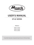
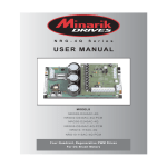
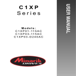
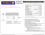
UPVFD04-115AC
14300 De La Tour Drive • South Beloit, IL 61080
Phone: (800) 646-2745 • Fax: (800) 394-6334
www.minarikdrives.com
Open Chassis Microprocessor-based
Variable Frequency AC Drive
115
115
Continuous
Motor Current
(Amps)
4.0
Motor
Horsepower
Range
1/8 - 1/2
AC Line Voltage .............................................................115 VAC ± 10%, 50/60 Hz, single phase
AC Line Current ...............................................................................................2x motor current
AC Motor Voltage...........................................................115 VAC, 60 Hz, single or three phase
Overload Capability ...............................................................................200% (2x) for 1 minute
Standard Carrier Frequency.............................................................................................16 kHz
Output Frequency Range............................................................................................0 - 120 Hz
Adjustable Maximum Output Frequency Range .....................................................30 - 120 Hz
Adjustable Minimum Output Frequency Range.......................................0 - 50% of maximum
Adjustable DC Injection Voltage................................................................................0 - 17 VDC
Acceleration Time Range.....................................................................................1 - 12 seconds
Deceleration Time Range.....................................................................................1 - 12 seconds
Analog Input Voltage Range (Signal must be isolated)................................................0 - 5 VDC
Input Impedance (S1 to S2) ....................................................................................>100K ohms
Vibration (20 - 50 Hz)..........................................................................................0.5G maximum
(>50 Hz) ..............................................................................................0.1G maximum
Ambient Temperature Range.....................................................................................0°C - 40°C
Weight ..............................................................................................................................1.4 lbs
Installation
0.188
[5]
TB501
DIR
S3
S2
STATUS
L1
LEDS
S1
115 VAC IN
E1
L2
115
E2
U
V
SW501
ON
MAX
MOTOR OUT
W
SLIP
COMP
MIN
ACCEL
DECEL/
DC BR
BOOST
TQ/LIM
1 2 3 4
3.45
[87.63]
ALL DIMENSIONS IN INCHES [MILLIMETERS]
Connections
Line Input
Connect the AC line power leads to terminals L1 and L2 115, or to a single-throw, single-pole master power
switch (recommended). The switch should be rated at a minimum of 120 VAC and 150% of line current.
NEUTRAL
MOTOR
L1
115 VAC IN
STATUS
LEDS
MAX
MIN
DECEL/
DC BR
TQ/LIM
DIR
S3
SPEED
POT
TB501
S2
S1
E1
ENABLE/ DISABLE
SWITCH
(open to disable)
E2
SW501
1 2 3 4
ON
Enable
Open the terminals E1 and E2 to coast the motor to minimum speed. Close terminals E1 and E2 to accelerate the
motor to set speed. If no enable switch is desired, jumper terminals E1 and E2. Do not use the enable for
emergency stopping.
ACCEL
Direction Switch
If a direction switch is desired, wire a switch to terminals E1 and DIR. When the connection is open, the motor will
run in the forward direction. When the connection is closed, the motor will run in reverse. If no direction switch is
desired, leave this connection open.
L2
115
MOTOR OUT
LOGIC
Speed Potentiometer
Use a 5K - 20K ohm, 1/4 W potentiometer for speed control. Connect the counter-clockwise end of the potentiometer
to S1, the wiper to S2, and the clockwise end to S3. If the potentiometer works inveresly of desired functionality,
(i.e. to increase motor speed, you must turn the potentiometer counterclockwise), power off the drive and swap
the S1 and S3 connections.
STOP
SWITCH
FUSE
U
Motor
If using a three phase motor, connect the AC motor leads to terminals U, V, and W. If the motor does not
spin in the desired direction, power down the drive and swap any two of these connections. If using a single
phase motor, connect the AC motor leads to terminals U and V. Refer to the Operations section for
possible wiring setups.
BOOST
Fusing
Minarik Drives drives require an external line fuse for protection. Use fast acting fuses rated for 250
VAC or higher and 150% of the maximum line current. Fuse the HOT leg of the AC line.
POWER
6.90 [17.5]
SLIP
COMP
Shielding Guidelines
As a general rule, Minarik Drives recommends shielding of all conductors. If it is not practical to shield
power conductors, Minarik Drives recommends shielding all logic-level leads. If shielding of logic-level
leads is not practical, the user should twist all logic leads with themselves to minimize induced noise.
Refer to the user’s manual for details on earth grounding shielded wires and filtering.
DO NOT INSTALL, REMOVE, OR REWIRE THIS EQUIPMENT WITH POWER APPLIED. Have a
qualified electrical technician install, adjust and service this equipment. Follow the National
Electrical Code and all other applicable electrical and safety codes, including the provisions of the
Occupational Safety and Health Act (OSHA), when installed equipment.
Circuit potentials are at 115 above earth ground. Avoid direct contact with the printed circuit
board or with circuit elements to prevent the risk of serious injury or fatality. Use a non-metallic
screwdriver for adjusting the calibration trim pots. Use approved personal protection equipment
and insulated tools if working on this drive with power applied.
Reduce the chance of an electrical fire, shock, or explosion by proper grounding, over-current
protection, thermal protection, and enclosure. Follow sound maintenance procedures.
Minarik Drives strongly recommends the installation of a master power switch in the line voltage
input. The switch contacts should be rated for 250 VAC and 200% of motor nameplate current.
Removing AC line power is the only acceptable method for emergency stopping. Do not use
DC injection braking, decelerating to minimum speed, or coasting to a stop for emergency stopping.
They may not stop a drive that is malfunctioning. Removing AC line power is the only acceptable
method for emergency stopping.
Line starting and stopping (applying and removing AC line voltage) is recommended for infrequent
starting and stopping of a drive only. DC injection braking, decelerating to minimum speed, or
coasting to a stop is recommended for frequent starts and stops. Frequent starting and stopping can
produce high torque. This may cause damage to motors.
Do not disconnect any of the motor leads from the drive unless power is removed or the drive is
disabled. Opening any one lead while the drive is running may destroy the drive.
Under no circumstances should power and logic level wires be bundled together.
Be sure potentiometer tabs do no make contact with the potentiometer enclosure. Grounding the
input will cause damage to the drive.
Caution should be taken when operating fan-cooled motors at low speeds because their fans may
may not move sufficient air to properly cool the motor. Minarik Drives recommends “inverter-duty”
motors when the speed range is beyond 10:1.
Drive is designed to work with permanent split capacitor, shaded pole, and standard three phase
induction motors. In general, the drive can work with capacitor-start motors, but it is conditional
on the current pull when the capacitor is in effect and how long the application calls for a speed that
the capacitor will stay in the auxiliary winding.
V
Wiring
Use 18 - 24 AWG wire for logic wiring (DIR, E1, E2, S1, S2, S3).
Use 14 - 16 AWG wire for AC line (L1, L2) and motor (U, V, W) wiring.
•
•
•
•
•
•
•
•
•
•
•
•
•
•
•
•
•
•
•
•
•
•
•
•
•
•
•
•
•
•
•
•
W
Mounting
• Drive components are sensitive to electrostatic discharge. Avoid direct contact with the circuit
• board. Hold the drive by the chassis only.
• Protect the drive from dirt, moisture, and accidental contact.
• Provide sufficient room for access to the terminal block and calibration trim pots.
• Mount the drive away from heat sources. Operate the drive within the specified ambient operating
• temperature range.
• Prevent loose connections by avoiding excessive vibration of the drive.
• Mount the drive with its board in either a horizontal or vertical plane. Four 0.20” (5 mm) wide slots
• in the chassis accept #8 pan head screws.
• The chassis should be earth grounded. Use a star washer beneath the head of at least one of the
• mounting screws to penetrate the anodized chassis surface and to reach bare metal.
Dimensions
Safety Warnings
READ ALL SAFETY WARNINGS BEFORE INSTALLING THIS EQUIPMENT
0.700 [17.80]
UPVFD04-115AC
Motor
Voltage
(VAC)
4.41 [112]
Model
Line
Voltage
(VAC)
3.71 [94.2]
Specifications
Full manuals available online
DIRECTION
SWITCH
AC LINE
VOLTAGE
115 VAC
HOT
Operation
Startup
SELECT SWITCHES
Select Switch (SW501)
Switch 1: ON - Manual Restart. Enable must be opened to clear fault and restart drive.
Switch 1: ON - Drive will fault for under-voltage or if the enable is closed when power is applied.
Switch 1: OFF - Auto Restart. Drive will restart when fault condition is removed.
Switch 1: OFF - Drive will fault for under-voltage. The drive will not fault if the enable is closed when
Switch 1: OFF - power is applied.
Switch 2: ON - DC Injection Braking. The drive will use DC injection braking to quickly decelerate the
Switch 2: ON - motor.
Switch 2: OFF - Coast to Stop. The fastest the motor will decelerate is a natural coast to a stop.
Switch 3: ON - 50 Hz motor setting
Switch 3: OFF - 60 Hz motor setting
Switch 4: ON - 1.6 kHz Carrier Frequency
Switch 4: OFF - 16 kHz Carrier Frequency
Calibration
MOTOR CONNECTIONS
Single Phase Operation - Non-reversing
For single phase operation, connect the motor as show in the figure below. Ensure that the prewired
capacitor and its associated motor coil are connected to terminals U and V as shown. This connection
may be internal if using a 2-wire motor. If the motor has three leads, you must make this connection
yourself.
PREWIRED
RUN CAPACITOR
AUXILIARY
WINDING
This connection may be
internal to the motor
(2-wire). If not, you must
make this connection
yourself.
MAIN
WINDING
TB501
DIR
S3
U
S2
STATUS
L1
LEDS
S1
115 VAC IN
U
V
W
V
E1
L2
115
E2
SW501
Dip Switch
(SW501)
ON
MAX
MOTOR OUT
SLIP
COMP
MIN
ACCEL
DECEL/
DC BR
BOOST
TQ/LIM
1 2 3 4
Single Phase Operation - Reversing
Remove the capacitor and connect the motor as show in the figure below. While allowing for solid-state
reversing, this wiring scheme may result in sub-optimal motor operation. Depending on the motor
construction and application requirements, the motor may need to be derated.
MAIN
WINDING
STARTUP
- Verify that no foreign conductive material is present on the printed circuit board.
- Ensure that all dip switches are properly set.
1. Turn the speed adjust potentiometer full counterclockwise (CCW).
2. Apply AC line voltage.
3. Enable the drive.
4. Slowly advance the speed adjust potentiometer clockwise (CW). The motor slowly accelerates as
the potentiometer is turned CW. Continue until the desired speed is reached.
5. Remove AC line voltage from the drive to coast the motor to a stop.
LEDs
Power (IL2): Green LED lights whenever AC line voltage is applied to the drive.
Solid: Power is applied and the output is disabled.
Flashing: Power is applied and the output is enabled.
Status (IL1): Red LED lights whenever a fault condition occurs.
Solid: Current Limit - The motor is asking for more current than drive is set to allow out.
2: Undervoltage - Internal DC BUS voltage dropped too low.
3: Overvoltage - Internal DC BUS voltage rose too high.
4: Short Circuit - Short circuit between any two phases on output.
5: Overtemperature Warning - Drive’s temperature is approaching critical temperature.
6: Overtemperature Shut Down - Drive’s temperature has reached critical temperature.
7: Manual Start Trip - Power was applied while the enable was closed (only applicable
7: if switch 1 on SW501 is set to ON).
TB501
DIR
Power
LED
S3
S2
STATUS
L1
LEDS
S1
115 VAC IN
E1
L2
115
E2
U
V
Status
LED
SW501
ON
MAX
MOTOR OUT
W
SLIP
COMP
MIN
ACCEL
DECEL/
DC BR
BOOST
TQ/LIM
1 2 3 4
Copyright 2011 by Minarik Drives - All right reserved. No part of this document may be reproduced
or retransmitted in any form without written permission from Minarik Drives. The information and
technical data in this manual are subject to change without notice. Minarik Drives makes no
warranty of any kind with respect to this material, including, but not limited to, the implied
warranties of its merchantability and fitness for a given purpose. Minarik Drives assumes no
responsibility for any errors that may appear in this document and makes no commitment to
update or to keep current the information in this document.
AUXILIARY WINDING
WITHOUT CAPACITOR
U
V
W
Three Phase Operation
For three phase operation, connect the motor as show in the figure below. Connect to terminals U, V,
and W as shown.
MOTOR
WINDING
MOTOR
WINDING
U
MOTOR
WINDING
V
W
Minimum Speed (MIN): The MIN setting determines the motor speed when the speed adjust
potentiometer is set for minimum speed. It is factory set for zero speed. To calibrate the MIN:
1. Set the MIN trim pot full CCW.
2. Set the speed adjust potentiometer for minimum speed (full CCW).
3. Adjust MIN trim pot until the desired minimum speed is reached.
Maximum Speed (MAX SPD): The MAX setting determines the motor speed when the speed adjust
potentiometer is set for maximum speed. To calibrate the MAX SPD:
1. Set the MAX SPD trim pot full CCW.
2. Set the speed adjust potentiometer for maximum speed (full CCW).
3. Adjust MAX SPD trim pot until the desired maximum speed is reached.
Slip Compensation (SLIP COMP): The SLIP COMP setting determines the degree to which motor speed
is held constant as the motor load changes. It is factory set for optimum motor regulation. To calibrate
the SLIP COMP:
1. Set the SLIP COMP trim pot full CCW.
2. Increase the speed adjust potentiometer until the motor runs at midspeed without load. A
2. handheld tachometer may be used to measure motor speed.
3. Load the motor to its full load current rating. The motor should slow down.
4. While keeping the load on the motor, rotate the SLIP COMP trim pot until the motor runs at
4. the speed measured in step 2. If the motor oscillates (overcompensation), the SLIP COMP trim
4. pot may be set too high (CW). Turn the SLIP COMP trim pot CCW to stabilize the motor.
5. Unload the motor.
Boost (BOOST): The BOOST setting increases the motor torque at low speeds. The minimum setting
is sufficient for most applications and does not need to be adjusted. If the motor stalls or runs
erratically at very low speeds (below 10 Hz), the boost trim pot may need adjustment. To calibrate the
BOOST:
1. Run the motor at the lowest continuous speed/frequency required.
2. Increase the BOOST trim pot until the motor runs smoothly. Continuous operation beyond the
2. motor’s current rating may damage the motor.
Acceleration (ACCEL): The ACCEL setting determines the time the motor takes to ramp to a higher
speed. ACCEL is factory set for the shortest acceleration time (full CCW). To calibrate the ACCEL:
1. Set the speed adjust potentiometer for minimum speed.
2. Set the speed adjust potentiometer for maximum speed. Measure the time is takes the motor
2. to go from minimum speed to maximum speed.
3. If the time measured in step 2 is not the desired acceleration time, turn the ACCEL trim pot
3. CW for a longer acceleration time, or CCW for a shorter acceleration time. Repeat steps 1
3. through 3 until the acceleration time is correct.
Deceleration / DC Injection Braking (DECEL/DC BR):
In Coast to Stop Mode (Dip Switch 2 = OFF), the Decel setting determines the time the motor takes to
ramp to a lower speed. Decel is factory set for the shortest deceleration time (full CCW). To calibrate
the DECEL:
1. Make sure Dip Switch 2 is OFF. See STARTUP section for dip switch location.
2. Set the speed adjust potentiometer for maximum speed.
3. Set the speed adjust potentiometer for minimum speed. Measure the time is takes the motor
3. to go from maximum speed to minimum speed.
4. If the time measured in step 2 is not the desired deceleration time, turn the DECEL trim pot
4. CW for a longer deceleration time, or CCW for a shorter deceleration time. Repeat steps 1
4. through 3 until the deceleration time is correct.
In DC Injection Braking Mode (Dip Switch 2 = ON), the DC Injection Braking setting determines the
amount of current injected into the motor to quickly brake the motor. To calibrate the DC BR:
1. Make sure Dip Switch 2 is ON. See STARTUP section for dip switch location.
2. Set the DC BR trim pot full CCW.
3. Enable the drive.
4. Turn up the speed adjust potentiomter to full speed.
5. Disable the drive.
6. If the motor decelerates to zero speed too slowly, increase the DC BR trim pot and repeat steps
6. 2 through 5 until the motor stops within the desired time.
Torque (TQ/LIM): The TQ/LIM setting determines the maximum torque for accelerating and driving
the motor. If torque limit adjustment is desireable, but not critical, use the chart below for
approximate TQ/LIM trim pot settings. Note that positions are relative to trim pot, not mounting
position (ie 8:00 is full CCW on trim pot).
1/2 HP
1/3 HP
1/4 HP
1/8 HP
100%
11:30
10:30
9:30
8:30
150%
2:00
11:30
10:30
9:00
200%
4:00
2:00
11:30
9:30
If torque limit adjustment is critical, determine the motor’s RMS current that correlates to desired
torque limit and then;
1. With power disconnected from the drive, connect a RMS ammeter in series with one of the
1. motor leads.
2. Turn the TQ/LIM trim pot to full CW. Apply power and adjust the motor speed to full rated
2. speed.
3. Load the motor so that it draws the RMS current previously determined.
4. Slowly turn the TQ/LIM trim pot CCW until the red LED starts flickering. Then turn the trim pot
4. slightly more so that it just starts to reduce the motor amps on the RMS ammeter.
250-0509 rev 1