1
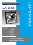
USER’S MANUAL
XP-AC SERIES
MODELS
XP02-115AC
XP05-115AC
XP10-115AC
Pulse-Width Modulated, Adjustable Speed Drives for DC Brush Motors
Copyright © 2006 by
Minarik Drives
All rights reserved. No part of this manual may be reproduced or transmitted in any form
without written permission from Minarik Drives. The information and technical data in this
manual are subject to change without notice. Minarik Corporation and its Divisions make no
warranty of any kind with respect to this material, including, but not limited to, the implied
warranties of its merchantability and fitness for a given purpose. Minarik Corporation and its
Divisions assume no responsibility for any errors that may appear in this manual and make
no commitment to update or to keep current the information in this manual.
Printed in the United States of America.
m Safety Warnings
• Have a qualified electrical maintenance technician install, adjust, and service this
equipment. Follow the National Electrical Code and all other applicable electrical and
safety codes, including the provisions of the Occupational Safety and Healthy Act
(OSHA) when installing equipment.
• Reduce the chance of an electrical fire, shock, or explosion by proper grounding, over
current protection, thermal protection, and enclosure. Follow sound maintenance
procedures.
• It is possible for a drive to run at full speed as a result of a component failure. Install a
master switch in the AC line for stopping the drive in an emergency.
• This drive is not isolated from earth ground. Circuit potentials are at 115 VAC above
earth ground. Avoid direct contact with the printed circuit board or with circuit elements
to prevent the risk of serious injury or fatality. Use a non-metallic screwdriver for adjusting the calibration trimpots.
ii
Table of Contents
Specifications
1
Dimensions
2
Installation
3
Mounting. . . . . . . . . . . . . . . . . . . . . . . . . . . . . . . . . . . . . . . . . . . . . . . . . . . . . . . . . . . . . . . . 3
Wiring. . . . . . . . . . . . . . . . . . . . . . . . . . . . . . . . . . . . . . . . . . . . . . . . . . . . . . . . . . . . . . . . . . . 3
Heat sinking . . . . . . . . . . . . . . . . . . . . . . . . . . . . . . . . . . . . . . . . . . . . . . . . . . . . . . . . . . . . . 4
Line Fusing . . . . . . . . . . . . . . . . . . . . . . . . . . . . . . . . . . . . . . . . . . . . . . . . . . . . . . . . . . . . . . 4
Speed adjust potentiometer . . . . . . . . . . . . . . . . . . . . . . . . . . . . . . . . . . . . . . . . . . . . . . . . 5
Connections . . . . . . . . . . . . . . . . . . . . . . . . . . . . . . . . . . . . . . . . . . . . . . . . . . . . . . . . . . . . . 6
Voltage Follower . . . . . . . . . . . . . . . . . . . . . . . . . . . . . . . . . . . . . . . . . . . . . . . . . . . . . . . . . . 7
Operation
8
Startup. . . . . . . . . . . . . . . . . . . . . . . . . . . . . . . . . . . . . . . . . . . . . . . . . . . . . . . . . . . . . . . . . . 8
Line starting and line stopping . . . . . . . . . . . . . . . . . . . . . . . . . . . . . . . . . . . . . . . . . . . . . . 8
Decelerating to a stop . . . . . . . . . . . . . . . . . . . . . . . . . . . . . . . . . . . . . . . . . . . . . . . . . . . . . 9
Dynamic braking. . . . . . . . . . . . . . . . . . . . . . . . . . . . . . . . . . . . . . . . . . . . . . . . . . . . . . . . 10
Calibration
12
MAX SPD. . . . . . . . . . . . . . . . . . . . . . . . . . . . . . . . . . . . . . . . . . . . . . . . . . . . . . . . . . . . . . 12
ACCEL/DECEL. . . . . . . . . . . . . . . . . . . . . . . . . . . . . . . . . . . . . . . . . . . . . . . . . . . . . . . . . . 12
IR COMP. . . . . . . . . . . . . . . . . . . . . . . . . . . . . . . . . . . . . . . . . . . . . . . . . . . . . . . . . . . . . . . 12
CURRENT LIMIT. . . . . . . . . . . . . . . . . . . . . . . . . . . . . . . . . . . . . . . . . . . . . . . . . . . . . . . . . 13
Application Notes
15
Multiple Fixed Speeds . . . . . . . . . . . . . . . . . . . . . . . . . . . . . . . . . . . . . . . . . . . . . . . . . . . 15
Adjustable speeds using potentiometers in series. . . . . . . . . . . . . . . . . . . . . . . . . . . . . 15
Independent adjustable speeds . . . . . . . . . . . . . . . . . . . . . . . . . . . . . . . . . . . . . . . . . . . 16
iii
RUN/JOG switch. . . . . . . . . . . . . . . . . . . . . . . . . . . . . . . . . . . . . . . . . . . . . . . . . . . . . . . . 16
Connection to other Minarik devices. . . . . . . . . . . . . . . . . . . . . . . . . . . . . . . . . . . . . . . . . 17
Leader-follower application . . . . . . . . . . . . . . . . . . . . . . . . . . . . . . . . . . . . . . . . . . . . . . . 18
Single speed potentiometer control of multiple drives . . . . . . . . . . . . . . . . . . . . . . . . . 18
Reversing. . . . . . . . . . . . . . . . . . . . . . . . . . . . . . . . . . . . . . . . . . . . . . . . . . . . . . . . . . . . . . 19
Troubleshooting
20
Replacement Parts
23
Limited Warranty
inside back cover
iv
Illustrations
Fig 1. XP-AC Series Dimensions . . . . . . . . . . . . . . . . . . . . . . . . . . . . . . . . . . . . . . . . . . . . . . . . . 2
Fig 2. Speed Adjust Potentiometer. . . . . . . . . . . . . . . . . . . . . . . . . . . . . . . . . . . . . . . . . . . . . . . 5
Fig 3. XP-AC Connections. . . . . . . . . . . . . . . . . . . . . . . . . . . . . . . . . . . . . . . . . . . . . . . . . . . . . . . 6
Fig 4. Voltage Follower Connection. . . . . . . . . . . . . . . . . . . . . . . . . . . . . . . . . . . . . . . . . . . . . . . 7
Fig 5. Run/Decelerate to Zero Speed Switch. . . . . . . . . . . . . . . . . . . . . . . . . . . . . . . . . . . . . . . 9
Fig 6. Dynamic Brake Connection. . . . . . . . . . . . . . . . . . . . . . . . . . . . . . . . . . . . . . . . . . . . . . 10
Fig 7. Typical CURRENT LIMIT and IR COMP Settings . . . . . . . . . . . . . . . . . . . . . . . . . . . . . . 14
Fig 8. Multiple Fixed Speeds. . . . . . . . . . . . . . . . . . . . . . . . . . . . . . . . . . . . . . . . . . . . . . . . . . 15
Fig 9. Adjustable Fixed Speeds using Potentiometers in Series. . . . . . . . . . . . . . . . . . . . . . 15
Fig 10. Independent Adjustable Speeds. . . . . . . . . . . . . . . . . . . . . . . . . . . . . . . . . . . . . . . . . 16
Fig 11. RUN/JOG Switch Connection to Speed Adjust Potentiometer . . . . . . . . . . . . . . . . . 16
Fig 12. Connecting an XP-AC Series Drive to a PCM4 or DLC600 . . . . . . . . . . . . . . . . . . . . . 17
Fig 13. Leader-Follower Application . . . . . . . . . . . . . . . . . . . . . . . . . . . . . . . . . . . . . . . . . . . . 18
Fig 14. Single Speed Potentiometer Control of Multiple Drives . . . . . . . . . . . . . . . . . . . . . . 18
Fig 15. Reversing Circuit Connection. . . . . . . . . . . . . . . . . . . . . . . . . . . . . . . . . . . . . . . . . . . 19
Specifications
Model
Max. Continuous Armature
Armature Current (Amps DC)
XP02-115AC
XP05-115AC
XP10-115AC
2
5
10 †
HP Range with
115 VAC Applied
1/20 - 1/8
1/4 - 1/2
1/2 - 1
† Use heat sink part number 223-0159 when operating the drive above 5 ADC.
AC Line Voltage
115 VAC, ±10%, 50/60 Hz, single phase
Armature Voltage Range
0–130 VDC
Form Factor (at base speed)
1.05
Acceleration/Deceleration Time Range (no load)
Analog Input Voltage Range [ isolated; S1 (+) to S2 (–) ]
Input Impedence (S1 to S2 with 5 VDC input)
Speed Regulation
Safety Certification
0.5 - 6 seconds
0–10 VDC
approximately 10K ohms
1% base speed or better
UL Recognized Component, file # E132235
CSA Certified Component, file # LR41380
Ambient Temperature Range (chassis drive)
10°C–40°C
Weight
XP02-115AC
0.66 lb
XP05-115AC
0.72 lb
XP10-115AC
0.82 lb
Dimensions
4.30 [109]
3.80 [97]
R502
R504
AA+
CURRENT
LIMIT
ACCEL /
DECEL
3.64 [93]
1.75 [44]
+ DC IN
+
0.19 [5]
6 PLACES
C501
R501
- DC IN
L
S1
W
S2
H
S3
R503
IR COMP
0.73 [19]
MAX SPEED
0.19 [5]
A
1.35 [34]
1.03 [26]
SIX MOUNTING SLOTS
0.19 [5] WIDE x 0.34 [9] DEEP
MODEL
DIMENSION “A”
XP02-115AC
XP05-115AC
XP10-115AC
1.77 [45]
2.36 [60]
2.88 [73]
FIGURE 1. XP-AC Series Dimensions
Installation
Mounting
• Drive components are sensitive to electrostatic fields. Avoid contact with the circuit
board directly. Hold drive by the chassis only.
• Protect the drive from dirt, moisture, and accidental contact. Provide sufficient room for
access to the terminal block and calibration trimpots.
• Mount the drive away from the other heat sources. Operate the drive within the specified ambient operating temperature range.
• Prevent loose connections by avoiding excessive vibration of the drive.
• Mount drive with its board in either a horizontal or vertical plane. Six 0.19 in. (5 mm)
wide slots in the chassis accept #8 pan head screws. Fasten either the large base or
the narrow flange of the chassis to the subplate.
• The Chassis must be earth grounded. Use a star washer beneath the head of at least
one of the mounting screws to penetrate the anodized chassis surface and to reach
bare metal.
Wiring
• Use 18 AWG wire for speed adjust potentiometer wiring. Use 16 AWG wire for motor
wiring.
• Twist logic wires (for speed adjust potentiometer) to avoid picking up unwanted electrical noise. Use shielded cable if wires are longer than 18 in. (46 cm).
• Keep logic wires away from power carrying lines or sources of electrical noise that
can cause erratic operation. Never run speed adjust potentiometer wires in the same
conduit used for motor and AC line voltage wires.
Installation
• It may be necessary to earth ground the shielded cable. If noise is produced by devices
other than the drive, ground the shield at the drive end. If noise is generated by a
device on the drive, ground the shield at the end away from the drive. Do not ground
both ends of the shield.
• Keep logic wires away from the power carrying lines or sources of electrical noise that
can cause erratic operation.
Heat sinking
Model XP10-115AC requires an additional heat sink when the continuous armature current is above 5 ADC. Use Minarik® part number 223-0159. All other chassis drives have
sufficient heat sinking in their basic configurations. Use a thermally conductive heat sink
compound (such as Dow Corning® 340 Heat Sink Compound) between the drive chassis
and heat sink surface for optimum heat transfer.
Line fusing
Protect all Minarik drives with AC line fuses. Use fast acting AC line fuses rated for 250
volts, and approximately 150% – 200% of the maximum armature current. Fuse only the
“hot” side of the AC line (L1) if using 115 VAC line voltage. See the chart below for recommended line fuse sizes.
Recommended Line Fuse Sizes
Maximum Armature
Current (DC Amps)
AC Line Fuse
Rating (AC Amps)
1.5 & below
2.6
3.5
5.0
7.6
10
3
5
8
10
15
15
Installation
Speed adjust potentiometer
Mount the speed adjust potentiometer through a 0.38 in. (10 mm) hole with the hardware
provided (Figure 2). Install the circular insulating disk between the panel and the 10K ohm
speed adjust potentiometer. Twist the speed adjust potentiometer wire to avoid picking up
unwanted electrical noise. If speed adjust potentiometer wires are longer than
18 in. (457 mm), use shielded cable. Keep speed adjust potentiometer wires
separate from power leads (L1, L2, A–, A+).
m WARNING
Be sure that the potentiometer tabs do not make contact with the potentiometer
enclosure. Grounding the input will cause damage to the drive.
MOUNT THROUGH A 0.38 IN. (10 MM) HOLE
CW
WIPER
CCW
NUT
STAR
WASHER
SPEED ADJUST
POTENTIOMETER
POT TAB ASSIGNMENTS
INSULATING DISK
PANEL
Figure 2. Speed Adjust Potentiometer
Installation
Connections
MOTOR
ARMATURE
R502
R504
AA+
ACCEL /
DECEL
Speed Adjust
Potentiometer
10K
+ DC IN
+
CURRENT
LIMIT
PRE-WIRED
C501
R501
- DC IN
L
S1
W
S2
H
S3
R503
CW
IR COMP
MAX SPEED
Fuse hot 115 VAC leg.
Fuse size typically
150% motor nameplate
continuous rating.
LINE VOLTAGE
Figure 3. XP-AC Connections
ASSUMPTIONS: Minarik drives supply motor voltage from A+ and A– terminals. It is assumed throughout this manual that, when A+ is positive with respect to A–, the motor will
rotate clockwise (CW) while looking at the output shaft protruding from the front of the
motor. If this is opposite of the desired rotation, simply reverse the wiring of A+ and A– with
each other.
Installation
Voltage follower
Instead of using a speed adjust potentiometer, the drive may be wired to follow a
0–10 VDC voltage signal that is isolated from earth ground (Figure 4). Connect signal
input (+) to S1. Connect the signal common (–) to S2. Make no connection to S3. A potentiometer can be used to scale the analog input voltage. To achieve greater linearity and
control, use an interface device such as Minarik® model PCM4 to scale the analog input
voltage. Follow the same wiring guidelines used for speed adjust potentiometer wiring (see
page 3.)
m WARNING
Do not connect a non-isolated input voltage signal to any XP Series drive. Connecting a
non-isolated signal will damage the drive.
R502
R504
AA+
ACCEL /
DECEL
0 – 10 VDC
Isolated Voltage
Signal Input
+
–
+ DC IN
+
CURRENT
LIMIT
C501
R501
- DC IN
L
S1
W
S2
H
S3
R503
IR COMP
MAX SPEED
Figure 4. Voltage Follower Connections
Operation
Startup
Note: Before applying power, verify that no conductive material is present on the printed
circuit board.
To start the drive:
1. Turn the speed adjust potentiometer full counterclockwise (CCW). If the drive is following a voltage signal, set the voltage signal to 0 VDC.
2. Apply AC line voltage.
3. Slowly advance the speed adjust potentiometer clockwise (CW). If the drive is following
a voltage signal, slowly increase the voltage signal. The motor slowly accelerates as
the potentiometer is turned CW, or the voltage signal is increased. Continue until the
desired speed is reached.
4. Remove AC line voltage from the drive to coast the motor to a stop.
If the motor or drive does not perform as described, disconnect the AC line voltage immediately. Refer to the Troubleshooting section for further assistance.
Line starting and line stopping
Line starting and line stopping (applying and removing AC line voltage) is recommended
for infrequent starting and stopping of a drive only. When AC line voltage is applied to the
drive, the motor accelerates to the speed set by the speed adjust potentiometer. When AC
line voltage is removed, the motor coasts to a stop.
Operation
Decelerating to a stop
A switch may be used to decelerate the motor to a stop. Connect the switch as shown in
Figure 5. Close the switch between S1 and S2 to stop the motor from set speed. Open the
switch to accelerate the motor to set speed. The ACCEL/DECEL trimpot setting determines
the rate at which the motor accelerates and decelerates, respectively.
CW
S3
10K Ohm
Speed Adjust
Potentiometer
S2
S1
CCW
RUN
STOP
Figure 5. Run/Decelerate to Zero Speed Switch
10
Operation
Dynamic braking
Dynamic braking may be used to rapidly stop a motor (Figure 6). For the simplest RUN/
BRAKE switch, use a double pole, double throw switch rated for at least the maximum DC
armature voltage and maximum braking current. For the most reliable control scheme, use
a relay with a delay on the make for the motor, and use a relay with a delay on the brake
for S1/S2.
A2
DYNAMIC
BRAKE
RESISTOR
MOTOR
BRAKE
A1
S3
RUN
CW
10K Ohm
Speed Adjust
Potentiometer
S2
S1
CCW
Figure 6. Dynamic Brake Connection
Operation
11
Size the dynamic brake resistor according to the motor current rating (see the table below).
The dynamic brake resistance listed in the table is the smallest recommended resistance
allowed to prevent possible demagnetization of the motor. The motor stops less rapidly
with higher brake resistor values.
Recommended Dynamic Brake Resistor Sizes
Motor Armature
Current Rating
Minimum Dynamic
Brake Resistor Value
Minimum Dynamic
Brake Resistor Wattage
less than 2 ADC
2–3 ADC
3–5 ADC
5–10 ADC
10–17 ADC
1 ohm
5 ohm
10 ohm
20 ohm
40 ohm
1W
5W
10W
20W
50W
For motors rated 1/17 horsepower and lower, a brake resistor is not necessary since the
armature resistance is high enough to stop the motor without demagnetization. Replace
the dynamic brake with 12 gauge wire.
m WARNING
Wait for the motor to completely stop before switching it back to RUN. This will prevent
high armature currents from damaging the motor or drive.
12
Calibration
Each drive is factory calibrated to its maximum horsepower rating. Readjust the calibration
trimpot settings to accommodate lower horsepower motors.
All adjustments increase with CW rotation, and decrease with CCW rotation. Use a non-metallic screwdriver for calibration. Each trimpot is identified on the printed circuit board.
MAX SPD
The MAX SPD setting determines the motor speed when the speed adjust potentiometer is
turned full CW. It is factory set for maximum rated speed.
To calibrate, set the MAX SPD trimpot full CCW. Turn the speed adjust potentiometer full
CW. Adjust the MAX SPD trimpot until the desired maximum motor speed is reached.
ACCEL/DECEL
The ACCEL/DECEL setting determines the time the motor takes to ramp to a higher (or
lower) speed. See Specifications on page 1 for approximate acceleration times. The
ACCEL/DECEL setting is factory set to its minimum value (full CCW).
Turn the ACCEL/DECEL trimpot CW to increase the acceleration and deceleration time, and
CCW to decrease the acceleration and deceleration time.
IR COMP
The IR COMP setting determines the degree to which motor speed is held constant as the
motor load changes. It is factory set for optimum motor regulation.
Recalibrate the IR COMP setting when using a lower horsepower motor. Refer to the recommended IR COMP settings on page 14, or recalibrate using the following procedure:
If the motor does not maintain set speed as the load changes, gradually rotate the IR
COMP trimpot CW. If the motor oscillates (overcompensation), the IR COMP trimpot may be
set too high (CW). Turn the IR COMP trimpot CCW to stabilize the drive.
Calibration
13
CURRENT LIMIT
The CURRENT LIMIT setting determines the maximum armature current output of the drive.
It is factory set at 120% of rated motor current.
Recalibrate the CURRENT LIMIT setting when using a lower horsepower motor. Refer to
the recommended CURRENT LIMIT settings on page 14, or recalibrate using the following
procedure:
1. With the power disconnected from the drive, connect a DC ammeter (0–15 A minimum
scale) in series with the armature.
2. Set the CURRENT LIMIT trimpot to minimum (full CCW).
3. Connect power to the drive. The motor should remain stopped.
4. Lock the motor armature. Be sure that the motor is firmly mounted.
5. Set the speed adjust potentiometer to maximum (full CW).
6. Adjust the CURRENT LIMIT trimpot CW slowly until the armature current is 120% of
motor rated armature current.
7. Set the speed adjust potentiometer to minimum and remove the stall from the motor.
m WARNING
Although the CURRENT LIMIT can be set to exceed the motor’s maximum armature
current rating, we recommend you do not run the motor continuously beyond that
rating. Continuous operating beyond the maximum armature current rating may cause
thermal degradation to the motor and drive.
14
Calibration
XP02-115AC
XP05-115AC
1/8 HP
90 VDC
1.3 ADC
CURRENT
LIMIT
1/2 HP
90 VDC
5 ADC
IR COMP
CURRENT
LIMIT
IR COMP
1/10 HP
90 VDC
1.1 ADC
CURRENT
LIMIT
1/3 HP
90 VDC
3.5 ADC
CURRENT
LIMIT
IR COMP
IR COMP
1/20 HP
90 VDC
0.56 ADC
CURRENT
LIMIT
1/4 HP
90 VDC
2.7 ADC
CURRENT
LIMIT
IR COMP
IR COMP
XP10-115AC
1 HP
90 VDC
10 ADC
CURRENT
LIMIT
IR COMP
3/4 HP
90 VDC
7.6 ADC
CURRENT
LIMIT
IR COMP
1/2 HP
90 VDC
5 ADC
CURRENT
LIMIT
IR COMP
Figure 7. Typical CURRENT LIMIT and IR COMP Settings
(actual settings may vary with each application)
15
Application Notes
Multiple fixed speeds
Replace the speed adjust potentiometer with series resistors with a total series resistance
of 10K ohms (Figure 8). Add a single pole, multi-position switch with the correct number of
positions for the desired number of fixed speeds.
R1
S3
R2
S2
R3
S1
Total Series
Resistance
10K Ohms
R4
Figure 8. Multiple Fixed Speeds
Adjustable speeds using potentiometers in series
Replace the speed adjust potentiometer with a single pole, multi-position switch, and two
or more potentiometers in series, with a total series resistance of 10K ohms. Figure 9
shows a connection for fixed high and low speed adjust potentiometers.
CW
S3
High
Speed
5K Ohm
S2
S1
Low
Speed
CW
5K Ohm
Figure 9. Adjustable Fixed Speeds Using Potentiometers in Series
16
Application Notes
Independent adjustable speeds
Replace the speed adjust potentiometer with a single pole, multi-position switch, and two
or more potentiometers in parallel, with a total parallel resistance of 10K ohms. Figure
10 shows the connection of two independent speed adjust potentiometers that can be
mounted at two seperate operating stations.
S3
SPEED 2
CW
CW
S2
SPEED 1
20K ohm
S1
20K ohm
Figure 10. Independent Adjustable Speeds
RUN/JOG switch
Using a RUN/JOG switch is recommended in applications where quick stopping is not
needed and frequent jogging is required. Use a single pole, normally closed, momentary
operated pushbutton for the JOB pushbutton as shown in Figure 11. When the RUN/JOG
switch is set to JOG, the motor decelerates to zero speed. Press the JOG pushbutton to jog
the motor. Return the RUN/JOG switch to RUN for normal operation.
CW
S3
S2
10K Ohm
S1
CCW
RUN
JOG
JOG
PUSHBUTTON
Figure 11. RUN/JOG Switch Connection to Speed Adjust Potentiometer
Application Notes
Connections to other Minarik devices
S3
PCM4
1
S2
2
S1
S3
DLC600
S1
S2
S2
S1
XP-AC
SERIES
DRIVE
XP-AC
SERIES
DRIVE
Figure 12. Connecting an XP-AC Series Drive to a PCM4 or DLC600
17
18
Application Notes
Leader-follower application
In this application, use a PCM4 to monitor the speed of the leader motor (Figure 13). The
PCM4 isolates the leader motor from the follower drive, and outputs a voltage proportional
to the leader motor armature voltage. The follower drive uses this voltage reference to set
the speed of the follower motor. An optional ratio potentiometer may be used to scale the
PCM4 output voltage.
A1
9
Leader
Drive
MOTOR
(+)
PCM4
8
A2
7
(-)
(+)
2
(-)
1
S1
Follower
Drive
TB502
TB501
S2
10K Ohm
(optional)
Figure 13. Leader-Follower Application
Single speed potentiometer control of multiple drives
Multiple drives can be controlled with a single speed adjust potentiometer using a PCM4
at the input of each drive to provide isolation (Figure 14). Optional ratio potentiometers can
be used to scale the PCM4 output voltage, allowing independent control of each drive.
6
8
2
ratio pot A
(optional)
10KΩ
PCM4
S1
A1
DRIVE A
7
1
TB501
MOTOR
A2
TB502
6
8
S2
2
PCM4
ratio pot B
(optional)
10KΩ
S1
A1
DRIVE B
7
TB501
1
S2
MOTOR
A2
TB502
Figure 14. Single Speed Potentiometer Control of Multiple Drives
Application Notes
19
Reversing
A dynamic brake may be used when reversing the motor direction (Figure 15). Use a three
pole, three positions switch rated for at least the maximum DC armature voltage and maximum braking current. Wait for the motor to stop completely before switching it to either the
forward or reverse direction. See the Dynamic braking section for sizing the dynamic brake
resistor.
Forward
A2
Brake
Reverse
Dynamic
Brake
Resistor
MOTOR
A1
S3
CW
10K Ohm
Speed Adjust
Potentiometer
S2
S1
CCW
Figure 15. Reversing Circuit Connection
20
Troubleshooting
m WARNING
Dangerous voltages exist on the drive when it is powered. When possible, disconnect
the AC line voltage from the drive while troubleshooting. Be alert. High voltages can
cause serious or fatal injury.
Perform the following steps before starting any procedure in this section:
• Disconnect AC line voltage from the drive.
• Check the drive closely for damaged components.
• Check that no conductive or other foreign material has become lodged on the printed
circuit board.
• Verify that every connection is correct and in good condition.
• Verify that there are no short circuits or grounded connections.
• Check that the drive’s rated armature output is consistent with the motor rating.
Motor does not run
1. Check for blown fuses or tripped circuit breaker.
2. Check that the speed adjust potentiometer is securely connected to S1, S2, and S3. If
an input voltage signal is used, check that the connections to S1 and S2 are secure.
3. Check that S1 and S2 are not shorted together.
4. Check that the drive recieves AC power at L1 and L2.
5. Check that the motor is not jammed or restricted from movement.
6. Check that the drive is not in current limit. Recalibrate the CURRENT LIMIT trimpot if it
is set too low (see page 14 for recommended trimpot settings).
Troubleshooting
Fuse blows or circuit breaker trips
1. Check all wiring for shorts, grounds, or misconnections.
2. Check that the drive is configured to match the motor rating.
3. Check that the motor is not jammed or restricted from movement.
4. Check that the fuse size is correct for the motor being driven.
Motor runs too fast at the maximum speed setting
1. Check that the MAX SPD setting is not set too high.
Motor runs in the opposite direction
1. Remove AC line voltage.
2. Reverse connections to the motor armature.
Motor slows under load
1. Check that the drive has been correctly calibrated for the motor.
2. Check that the motor is not overloaded.
3. Readjust the IR COMP slightly CW until motor runs at proper speed.
Motor is unstable under load
1. Readjust the IR COMP setting slightly CCW until the motor speed stabalizes.
21
22
Troubleshooting
Motor only runs at full speed
1. Check that S2 and S3 are not shorted together.
For additional assistance, contact your local Minarik Drives distributor, or the factory direct:
(800) MINARIK or (800) 646-2745.
23
Replacement Parts
Replacement parts are available from Minarik Drives and its distributors for this drive
series.
Model No.
Symbol
Description
Minarik P/N
XP02-115AC
C501
D501
Q502
R501, 502
R503
R504
BR601
220 μF, 200 V Capacitor
16 A, 300 V Diode
Power MOSFET
0.2 Ohm, 5 W Resistor
8.2 K Ohms, 5 W Resistor
3.3 K Ohms, 10 W Resistor
25 A, 800 V Diode Bridge
10 K Ohm Potentiometer Kit
011-0069
071-0054
070-0043
032-0093
032-0126
032-0131
073-0007
202-0066
XP05-115AC
C501
D501
Q501, 502
R501, 502
R503
R504
BR601
1000 μF, 200 V Capacitor
16 A, 300 V Diode
Power MOSFET
0.05 Ohm, 5 W Resistor
8.2 K Ohm, 5 W Resistor
3.3 K Ohm, 10 W Resistor
25 A, 800 V Diode Bridge
10 K Ohm, Potentiometer Kit
011-0096
071-0054
070-0043
032-0113
032-0126
032-0131
073-0007
202-0066
XP10-115AC
C501
D501
Q501, 502
R501, 502
R503
R504
BR601
1500 μF, 250 V Capacitor
16 A, 300 V Diode
Power MOSFET
0.01 Ohm, 5 W Resistor
8.2 K Ohm, 5 W Resistor
3.3 K Ohm, 10 W Resistor
25 A, 800 V Diode Bridge
10 K Ohm Potentiometer Kit
011-0089
071-0054
070-0043
032-0129
032-0126
032-0131
073-0007
202-0066
24
NOTES
25
Limited Warranty
A. Warranty - Minarik Corporation (referred to as “the Corporation”) warrants that its products will
be free from defects in workmanship and material for twelve (12) months or 3,000 hours, whichever comes first, from date of manufacture thereof. Within this warranty period, the Corporation
will repair or replace, at its sole discrection, such products that are returned to Minarik Corporation, 14300 De La Tour Dr., South Beloit, IL 61080 USA.
This warranty applies only to standard catalog products, and does not apply to specials. Any
returns for special controls will be evaluated on a case-by-case basis. The Corporation is not
responsible for removal, installation, or any other incidental expenses incurred in shipping the
product to and from the repair point.
B. Disclaimer - The provisions of Paragraph A are the Corporation’s sole obligation and exclude all
other warranties of merchantability for use, express or implied. The Corporation further disclaims
any responsibility whatsoever to the customer or to any other person for injury to the person or
damage or less of property of value caused by any product that has been subject to misuse, negligence, or accident, or misapplied or modified by unauthorized person or improperly installed.
C. Limitations of Liability - In the event of any claim for breech of any of the Corporation’s
obligations, whether express or implied, and particularly of any other claim or breech of warranty
contained in Paragraph A, or of any other warranties, express or implied, or claim of liability that
might, despite Paragraph B, be decided against the Corporation by lawful authority, the Corporation shall under no circumstances be liable for any consequential damages, losses, or expense
arising in connection with the use of, or inability to use, the Corporation’s product for any purpose
whatsoever.
An adjustment made under warranty does not void the warranty, nor does it imply an extension of
the original 12-month warranty period. Products serviced and/or parts replaced on a no-charge
basis during the warranty period carry the unexpired portion of the original warranty only.
If for any reason any of the foregoing provisions shall be ineffective, the Corporation’s liability for
damages arising out of its manufacture or sale of equipment, or use thereof, whether such liability
is based on warranty, contract, negligence, strict liability in tort, or otherwise, shall not in any event
exceed the full purchase price of such equipment.
Any action against the Corporation based upon any liability or obligation arising hereunder or
under any law applicable to the sale of equipment or the use thereof, must be commenced within
one year after the cause of such action arises.
MINARIK DRIVES
www.minarikdrives.com
14300 De La Tour Dr., South Beloit, IL 61080
Phone: (800) MINARIK (646-2745); Fax: (815) 624-6960
Document Number: 250-0219; Revision 1. Printed in the U.S.A. -- August 2006