1
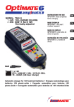
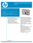
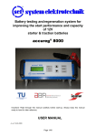
Revision: R4
INTRODUCTION
z The OC-SW121020 is switching mode MCU battery charger with recovery mode function.
z It is designed for Lead-acid or Gel batteries and keeps the batteries in long-life. The charger has the
normal charging mode and manual recovery mode.
z The normal charging mode includes three stages. There is bulk charging mode (C.C mode), absorption
mode (C.V mode) and Maintenance mode (Float mode).
z The manual recovery mode contains four stages. There is 24 hours recovery mode, bulk charging (C.C
mode), absorption mode (C.V mode) and maintenance mode (Float mode)
z The recovery mode uses a unique waveform to help remove the effects of sulphate.
z Please read these operating instructions carefully before operating the OC-SW121020
battery charger.
IMPORTANT SAFETY INSTRUCTIONS
1. SAVE THESE INSTRUCTIONS - THIS MANUAL CONTAINS IMPORTANT SAFETY AND
OPERATING INSTRUCTIONS FOR 12V 2A BATTERY CHARGERS, Model No.: OC-SW121020
KEEP IT WITH OR NEAR CHARGER AT ALL TIMES.
2. WARNING - EXPLOSIVE GASES DEVELOP DURING NORMAL BATTERY
OPERATION. IT’S VERY IMPORTANT THAT YOU READ THIS MANUAL AND FOLLOW
THESE INSTRUCTIONS BEFORE USING YOUR CHARGER.
3. To reduce the risk of battery explosion, follow these instructions and those published by battery
manufacturer and manufacturer of any equipment you intend to use in the vicinity of the battery. Review
cautionary marking on these products and on the engine.
4. Do not expose charger to rain, snow, or liquids.
5. Use of an attachment not recommended or sold by the battery charger manufacturer may result in a risk of fire,
electric shock, or injury to persons.
6. To reduce risk of electric shock, unplug the charger from the AC outlet before attempting any maintenance or
cleaning.
7. If charger is equipped with an input power cord, do not operate charger with damaged cord or plug - replace the cord
or plug immediately.
8. Do not operate charger if it has received a sharp blow, been dropped, or otherwise damaged in any way; take it to a
qualified serviceman.
9. Do not disassemble charger; take it to a qualified service center when service or repair is required. Incorrect
reassembly may result in a risk of electric shock or fire.
10. Appliances incorporating batteries which contain materials hazardous to the environment:
10.1 Batteries contain lead and dilute sulfuric acid. Dispose of the battery in accordance with federal, state and local
regulations. Do not dispose of the battery in a landfill, lake or other.
10.2 Scrap and replace the VRLA battery at or before the time indicated on the battery or in the user's manual.
Usage beyond the required time of service can cause fluid leakage due to damages to the container, or cause fire
due to power leakage.
11. Warning against recharging non-rechargeable batteries.
12. PERSONAL PRECAUTIONS
a) The appliance is not intended for use by young children or infirm persons without supervision; young children should be
supervised to ensure that they do not play with the appliance.
b) When the battery charger is charging for automobile batteries, the following steps should be done:
b.1 The battery terminal is not connected to the chassis has to be connected first. The other connection is to be made
to the chassis, remote from the battery and fuel line. The battery charger is then to be connected to the supply mains.
OC-SW121020 12V 2A User Manual R4.doc1
P.1/5
Issue date :2007-Dec-20
Revision: R4
b.2 After charging, disconnect the battery charger from supply mains, and then remove the chassis connection and
the battery connection, in this order.
c) For appliance with type Y attachment:
If the supply cord is damaged, it must be replaced by the manufacturer or by a service agent or similarly qualified
person in order to avoid a hazard.
d) Someone should be within range of your voice or close enough to come to your aid when you work near a Lead-acid
battery. Have plenty of fresh water and SOAP nearby in case battery acid contacts skin, clothing or eyes. Wear
complete eye and clothing protection. Avoid touching eyes while working near battery.
e) If battery acid contacts skin or clothing, wash immediately with soap and water. If acid enters eye, immediately flush
eye with running cold water for at least 10 minutes and get medical attention immediately.
f) NEVER smoke or allow a spark or flame in vicinity of battery or engine.
g) Be extra cautious to reduce risk of dropping a metal tool onto battery. It might spark or short-circuit battery or other
electrical part that may cause explosion.
h) When working with a lead-acid battery, remove personal metal items such as rings, bracelets, necklaces, watches, etc.
A lead-acid battery can produce a short-circuit current high enough to weld a ring or the like to metal, causing a severe
burn.
i) Use charger for charging a 12-Volt Lead-Acid or GEL Battery with 6 cells only. The rated capacity of the battery should
be 40 ampere-hours maximum. It is not intended to supply power to a low voltage electrical system. Do not use
battery charger for recharging dry-cell or non-rechargeable batteries that are commonly used with home
appliances. These batteries may burst and cause injury to persons and damage to property.
j) NEVER charge a frozen battery.
13. PREPARING TO CHARGE
a) If necessary to remove battery from vehicle to charge, always remove grounded terminal from battery first. Make sure
all accessories in the vehicle are off, so as not to cause an arc. Be sure area around battery is well ventilated while
battery is being charged. Gas can be forcefully blown away by using a piece of cardboard or other non-metallic
material as a fan.
b) Clean battery terminals. Be careful to keep corrosion from coming into contact with eyes. Add distilled water in each cell
until battery acid reaches level specified by battery manufacturer. This helps purge excessive gas from cells. Do not
overfill. For a battery without caps, carefully follow manufacturer's recharging instructions.
c) Study all battery manufacturers’ specific precautions such as removing or not removing cell caps while charging and
recommended rates of charge.
d) Determine voltage of battery by contacting battery manufacturer and make sure it matches output rating of battery
charger.
e) Slide Switch is selected to GEL position for charge GEL Battery.
f) Slide Switch is selected to Lead-acid position for charge Lead-acid Battery.
14. CHARGER LOCATION
a) Position the charger as far away from battery as dc cables permit.
b) Never place charger directly above battery being charged; gases from battery will corrode and damage charger.
c) Never allow battery acid to drip on charger when reading gravity or filling battery.
d) Do not operate charger in a closed-in area or restrict ventilation in any way.
e) Do not set a battery on top of charger.
15. DC CONNECTION PRECAUTIONS
a) Connect and disconnect DC output terminals only after removing charger from AC outlet.
b) Never allow DC output terminals to touch each other.
c) If problems arise connecting the output leads, solicit the aid of your Dealer from whom you purchased this product or
the charger manufacturer for finding a suitable connection device for your application.
16. FOLLOW THESE STEPS WHEN BATTERY IS INSTALLED IN VEHICLE.
A SPARK NEAR BATTERY MAY CAUSE BATTERY EXPLOSION. TO
REDUCE RISK OF A SPARK NEAR BATTERY:
a) Position AC and DC cords to reduce risk of damage by hood, door or moving engine part.
b) Stay clear of fan blades, belts, pulleys, and any other parts that can cause injury to persons.
c) Check polarity of battery posts POSITIVE (POS., P, +) post usually has larger diameter than NEGATIVE - (NEG., N, -).
OC-SW121020 12V 2A User Manual R4.doc1
P.2/5
Issue date :2007-Dec-20
Revision: R4
d) Determine which post of battery is grounded (connected) to chassis.
If negative post is grounded (as in most
vehicles), see paragraph (e). If positive post is grounded, see paragraph (f).
e) For negative-grounded vehicle, first connect POSITIVE (RED) clip from charger to POSITIVE (POS., P, +) ungrounded
post of battery. Then connect NEGATIVE (BLACK) terminal to vehicle chassis or engine block away from battery.
f) For positive-grounded vehicle, connect NEGATIVE (BLACK) clip from charger to NEGATIVE (NEG., N, -) ungrounded
post of battery. Connect POSITIVE (RED) clip to vehicle chassis or engine block away from battery keeping the
battery terminal well removed there from.
g) Do not connect any charger clips to carburetor, fuel lines, or sheet-metal body parts. Connect to a heavy gauge metal
part of the frame or engine block.
h) When disconnecting charger, turn switches (if supplied) to off, disconnect charger from AC power, remove clip from
vehicle chassis, and then remove clip from battery terminal. See operating instructions for length of charge information.
17. FOLLOW THESE STEPS WHEN BATTERY IS OUTSIDE VEHICLE. A
SPARK NEAR THE BATTERY MAY CAUSE BATTERY EXPLOSION. TO
REDUCE RISK OF A SPARK NEAR BATTERY:
a) Check polarity of battery posts.
POSITIVE (POS., P, +) battery post usually has a larger diameter than NEGATIVE
(NEG., N, -) post. Some batteries are equipped with 'Wing-Nut' terminals allowing for easy placement of the
terminals to these posts.
b) Attach at least a 24-inch long 18-gauge (AWG) insulated battery cable to NEGATIVE (NEG., N, -) battery post.
c) Connect POSITIVE (RED) charger terminal to POSITIVE (POS., P, +) post of battery.
d) Position yourself and free end of cable as far away from battery as possible - then connect NEGATIVE (BLACK)
terminal to free end of cable.
e) Do not face battery when making final connection.
f) When disconnecting charger, always do so in reverse sequence of connecting procedure and break first connection
while as far away from battery as practical
OPERATING INSTRUCTIONS
BATTERY TYPES AND CHARGING MODE SETTING
BATTERY TYPES
This charger is designed for LEAD-ACID or GEL Batteries. It can charge LEAD-ACID or GEL batteries. Before you plug in
AC power and connect battery clamp to the battery, you must select either LEAD-ACID or GEL mode with the
LEAD-ACID/GEL slide switch.
CHARGING MODE SETTING
a) NORMAL CHARGING MODE
ALL LED’s will turn ON for a second when A.C. Power is present. It will then go to the NORMAL CHARGING MODE
automatically.
There are three stages:
1) Bulk Charging Mode (C.C. Mode)
Charging Green LED is flashing.
The battery can be charged about 80%. The charger delivers an almost constant current 2A until the battery
voltage reaches the set value.
2) Absorption Mode (C.V. Mode)
Charging Green LED is flashing.
The battery can charge up to almost 100%. The charging current tapers and the charging voltage is kept
constant at the set value.
3) Maintenance Mode (Float Mode)
Charging Green LED on continuously.
The Float Mode allows the charger to effectively be left connected to your batteries, over the course of a season,
without overcharging your batteries, and maintains your battery in a good condition if it is not being used. The
‘Float Mode’also contains a special charging waveform, that pulses power into your batteries, and helps to peak
the power into your battery.
OC-SW121020
12V 2A User Manual R4.doc1
P.3/5
Issue date :2007-Dec-20
Revision: R4
b) MANUAL BATTERY RECOVERY MODE
ALL LED’s will turn ON for a second when A.C. Power is present.
There are four stages:
1) 24 Hours Battery Recovery Mode
Once the recovery button is pressed. It will switch to 24 hours Battery Recovery mode. The ‘Battery Recovery
Mode’contains a special Pulse waveform, which pulses power into your batteries, and helps to remove the
effects of sulphation. After 24 hours or by pressing the recovery button, the charger will determine the battery
condition and whether or not it is healthy.
2) Bulk Charging Mode (C.C. Mode)
The battery can be charged about 80%. The charger delivers an almost constant current 2A until the battery
voltage reaches the set value.
3) Absorption Mode (C.V. Mode)
The battery can charge up to almost 100%. The charging current tapers and the charging voltage is kept
constant at the set value.
4) Maintenance Mode (Float Mode)
The Float Mode allows the charger to effectively be left connected to your batteries, over the course of a
season, without overcharging your batteries, and maintains your battery's full charge. The ‘Float Mode’ also
contains a special charging waveform, that pulses power into your batteries, and helps to peak the power into
your battery.
LED INDICATORS
Power LED
Recovery LED
Charging LED
LED
Status
Power LED (RED)
Red
ON
Red
Flash
Recovery LED(YELLOW / RED)
Yellow / Red
Alternative Flash
Red
ON
Charging LED (GREEN)
Green
Flash
Green
ON
OC-SW121020
12V 2A User Manual R4.doc1
Descriptions
AC Power is connected
Short Circuit or Polarity Reversed
Battery Recovery mode is in progress.
Battery Recovery Fail
CC./CV. mode
The charger is at Float mode
P.4/5
Issue date :2007-Dec-20
Revision: R4
TECHNICAL DATA
a)
b)
c)
d)
e)
f)
g)
h)
i)
j)
k)
l)
m)
n)
o)
p)
AC Input Voltage:
240V, 50Hz
Rated output Current:
2.0A @14.5V (AC input voltage at 240Vac 50Hz)
Charging starting condition at Normal charging mode: 9V
Charging Voltage at Absorption mode (C.V mode) for Lead-Acid battery: 14.5V
Charging Voltage at Absorption mode (C.V mode) for Gel battery: 14.1V
Charging Voltage at Maintenance mode (Float mode): 13.5V
Operating temperature:
-10 to 40*C
Storage temperature:
-10 to 80*C
Operating humidity range:
90% R.H max.
Cooling method:
Natural Convection
Type of batteries:
Lead-Acid or GEL batteries
Battery Capacity:
3 – 40Ah
Enclosure dimensions:
L140 x W65 x H42 mm
AC Power cord:
H05VVH2-F 2 x 0.75mm2 with 2 PIN plug, external length 6 feet
Output DC Cord:
SPT-2 18/2C with color coded battery clamp, external length 6 feet
Weight:
450g
SAFETY PROTECTION
The charger contains four safety protections. They are:
a) INTERNAL OVERHEAT PROTECTION
b) OVERLOAD PROTECTION
c) REVERSE POLARITY
d) SHORT CIRCUIT PROTECTION
The OC-SW121020 has a built in overheat and overload electronic circuit. When the charger is overheated,
the charger will shut down shortly. If temperature is decreased, the charger will resume to normal charging.
The charger employs the use of a‘Solid State Circuit Interrupter’ that opens under severe overload. This condition may
occur if attempting to charge any severely discharged or heavily sulfated battery. Once the Interrupter opens, the charger
will stop charging for a short period and then resume charging automatically and the Charging LED. will be OFF, until
resume charging. Overloading could be due to an external load, remove the load condition prior to attempting to recharge
the battery.
The charger has reverse battery and short circuit protection. If a reverse battery or charger output lead short condition
exists (Red LED flashes, while output leads are connected backwards), simply unplug charger from AC power and
properly remake the connections as described in this manual. The charger employs the use of solid state circuit
protectors on both the input and output sections (as compared to unreliable bimetallic automatic breakers), that will
permanently open during a catastrophic failure like the shorting of output leads while charging or lightening strikes etc.
MAINTENANCE
Store in a clean, dry place. Remove the plug from the power socket before attempting any maintenance or cleaning.
Occasionally, clean the case using a damp cloth and mild cleaning agent. If the power cable is damaged, take it to a
qualified service center.
OC-SW121020
12V 2A User Manual R4.doc1
P.5/5
Issue date :2007-Dec-20