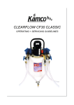
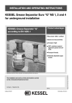
1
INSTALLATION AND OPERATING INSTRUCTIONS
KESSEL septic systems - INNO-CLEAN®
- the complete biological septic system for cleaning domestic
wastewater in keeping with DIN 4261 Part II/EN 12566
General construction supervisory approval: Z-55.3-85
•
•
•
•
•
INNO CLEAN EW4
EW 6
EW 8
Single tank systems
For burying in the ground
Art. No.: 97600 / 97610 / 97620
Product Advantages
Low costs of maintenance
Long service life and water seal
tightness thanks to seamless
monolithic construction
High degree of resistance to
corrosive wastewater
Easy installation due to low
weight
Special materials make it shatterproof
Recyclable
he installation and service of this unit should be carried
out by a licensed professional servicer
Company - Telephone No.
Edition 09/2005-HG
(Subject to technical amendments)
ID number 010-693
4) / 85445/80B(D) / 85460/80B(D)
(D) / 85545/80B(D) / 85560B(
Dear Customer,
Before the KESSEL - INNO-CLEAN® septic system is installed and placed in operation please
carefully read and follow all of the instructions contained in this Installation, Maintenance and
User's Manual.
Upon delivery of the septic system please thoroughly inspect it to make sure that it has not been
damaged during shipping. In case damage has occurred to the separator, please follow the
instructions listed in the ‚Guarantee section of this user's manual.
KESSEL GmbH
2
Table of Contents
1. Safety instructions
Page 4
2. General
2.1 Area of use
2.2 Description of system
2.3 Functional description
Page 5
Page 5
Page 6
3. Packing, transport and storage
3.1 Packing
3.2 Transport
3.3 Storage
Page 8
Page 8
Page 8
4. Installation and mounting
4.1 Overview of installation steps
4.2 Tank installation
4.2.1 Backfilling material
4.2.2 Pit
4.2.3 Tests prior to installation
4.2.4 Installation
4.2.5 Fitting the attachments
4.3 Control unit installation
4.3.1 Fitting the control system and compressor
4.3.2 Connecting the control unit to the aeration hoses
Page 9
Page 9
Page 9
Page 9
Page 10
Page 10
Page 11
Page 12
Page 12
Page 13
5. Start-up
5.1 Ensuring proper functioning of system
5.2 Briefing / Hand-over
Page 21
Page 21
6. Operation and waste disposal
6.1 Operation
6.2 Operator's own checks
6.3 Waste disposal instructions
6.4 Waste disposal
Page 22
Page 22
Page 24
Page 25
7. Maintenance
Page 26
8. Specifications
8.1 Dimensional drawing
8.2 Cleansing figures and power consumption
Page 26
Page 27
9. Control of the septic system
9.1 Messages of the control unit
9.2 Menu guide
Page 28
Page 30
10. Malfunctions and remedial steps
11. Guarantee
12. Septic system characteristics
13. Important contacts / info
Page 32
Page 33
Page 34
Page 35
3
1. Safety instructions
The personnel for installation, operation, maintenance and repair must have the
appropriate qualifications for this work.
The operator is to precisely regulate responsibility, the field of responsibility and
supervision of personnel.
The operational reliability of the supplied system is only ensured given use as
conforming to purpose
On no account are standards associated with the specifications to be fallen
short of.
This system is provided with electrical voltages and controls mechanical system
parts. Non-observance of the operating instructions could result in considerable
material damage, injuries or terminal accidents.
The accident prevention provisions and appropriate DIN/VDE standards and
directives are to be followed when installing, operating, maintaining and
repairing the system.
These include:
• "Accident prevention provisions – construction work" BGV C22, up to now VBG
37
• "Pits and ditches, slopes, working area width, trench shoring" DIN 4124
• "Laying and testing wastewater lines and channels" DIN EN 1610
• "Directives for working in tanks and confined spaces" BGR 117 – up to now
ZH1/77
• Directives of the local energy supply concerns are to be observed.
The access cover of the septic system must be satisfactorily secured against
unauthorised opening (especially by children) - even during breaks from work.
Warning
The system is made up of a number of components. Therefore consult the
individual chapters in the operating instructions. Only when the complete system
is shut down by pulling out the mains plug at the control unit and secured
against being turned on again is any component to be installed, maintained,
inspected or repaired.
The control unit is under voltage and must not be opened.
Only electrical specialists are allowed to work on electrical equipment.
The electrical specialist term is defined in VDE 0105.
Work on the air compressor going beyond that described in the inspection and
maintenance chapter is not allowed.
It is to be ensured that the electrical wiring and all other electrical system parts
are in good working order. Under no circumstances is the system to be started if
damage is present.
Please note !
The system may only be updated or modified in consultation with the
manufacturer. The purpose of genuine spare parts and manufacturer-approved
accessories is to uphold safety. Use of other parts can nullify the liability for the
resulting consequences.
4
2. General
2.1 Area of use
INNO-CLEAN®, the septic system from KESSEL, is a cleaning unit for domestic wastewater in
keeping with DIN 4261 Part II / EN 12566. It is not envisaged for precipitation and animal
husbandry and swimming pool wastewater. This septic system biologically cleans domestic
wastewater and automatically adapts to the quantities arising. The wastewater is collected and
cleaned in a plastic tank.
This tank is envisaged for trench shoring in the ground.
A control unit automatically regulates aeration and agitation. It is envisaged for unobstructed
installation in frost-protected, dry rooms which are safeguarded from flooding. In addition to the
septic system, provision must be made for a suitable wastewater discharge line in keeping with
ATVDVWK –A138. Furthermore, the council, country district or district water authority is
responsible for installation and operation approval.
2.2 Description of system
KESSEL-INNO-CLEAN® consists of two principal segments.
The control unit is in a frost-free, dry room safeguarded from flooding;
the plastic tank housing the cleansing process is buried in the ground.
1. Control unit (controller and air compressor)
2. Inlet
3. KESSEL-INNO-CLEAN® tank
4. Load-class B (12.5 ton) cast iron covers (child-proof)
5. KESSEL-INNO-CLEAN® activation system
6. Pre-septic chamber
7. Separation wall
8. Activation chamber
9. Sampling chamber
10. Well drain (optional)
5
2. General
2.3 Functional description
Cleansing is automatically carried out by the control unit. A cleansing cycle lasts some 8 hours and
is ended with the cleansed water being discharged.
The next cleansing process is automatically started given enough wastewater in the pre-cleansing
chamber. Cleansing is based on microorgansims which clean the wastewater during the treatment
phase.
A lack of oxygen arises between the aeration phases thus forcing the microorganic culture to
continue the metabolism in the anaerobic range. The altered metabolism results in nitrate and
nitrite decomposing into harmless gaseous nitrogen (denitrification).
This treatment phase lasts for six hours.
1. Feeding-in the black wastewater (all the domestic wastewater)
All domestic wastewater gets into the pre-cleansing chamber.
The solids settle to the bottom and form a sludge layer.
2. Filling the activation chamber
The activation chamber is filled with the wastewater from the pre-cleansing chamber. The
wastewater sludge remains in the pre-cleansing chamber, is compressed and must be disposed of
once maximum capacity has been reached.
6
2. General
3. Wastewater treatment phase
Short aerator surges stir up the wastewater in the activation chamber. Oxygen gets into the
wastewater due to phased aeration and microorganisms explode in number. During aeration the
metabolism of the microorganisms cleans the wastewater of ammonium, iron, manganese and
organic compounds.
4. Settling phase
A two-hour settling phase follows the treatment phase.
All the solids in the wastewater can settle and a sludge layer of microorganisms forms at the
bottom.
5. Discharging the clear water
The cleansed water remaining above this sludge layer is automatically drained. At the same time,
the sludge layer is pumped from the bottom of the cleansing chamber into the pre-cleansing
chamber.
7
3. Transport and Storage
3.1 Transport
Transportation of the KESSEL separator should be
handled only by a transporter who has the proper
knowledge, equipment and employees to handle such
a product. During transport the separator must be
firmly fixed into position and must not be allowed to
move or shift in place. It also must be protected from
other objects coming in contact with the separator
during transport.
If and when the separator is lifted it is important to
follow the following correct procedures: The separator
is not to be lifted with the use of steel cables or chains.
Proper equipment are heavy duty cloth or hemp straps
designed to handle the corresponding loads. The
separator should be lifted by placing the proper straps
beneath the inlet and outlet of the separator as seen in
the illustration. Do not lift the separator by the small
holes between the two manholes covers as illustrated
on this page. In instances where a forklift is used,
secure the separator to the forklift with appropriate
cloth / hemp securing straps.
3.2 Storage
In cases where the separator needs to be temporarily
stored before installation, it is important that the
separator is placed on firm level ground and in an area
where it is protected from coming in contact with other
objects. Storing the separator outdoors will not cause
any problems.
8
4. Installation and mounting
When temporarily storing the septic system and up the end of installation, appropriate
protective steps must be initiated at the site to prevent accidents as well as damage to the
septic system.
Notice is to be taken of the chapter on safety instructions.
4.1 Overview of installation steps
1. Dimension float switch cable and aeration hose and determine where the pit is to be positioned.
2. Excavate the pit.
3. Fill with earth gravel, draw off horizontally and shake.
4. Transfer tank into the pit.
5. Piping of supply and discharge.
6. Install aeration hoses and float switch cable in a DN 150 empty tube.
7. Mount and connect air compressor and control unit
8. Fill tank with water (water up to the underside of the supply and drain pipe)
9. Backfill tank with gravel and compact (up to under the drain)
10. Put on attachments and fix clamping ring.
11. Backfill the top layer in keeping with use wanted.
12. Mount access covers on the shafts.
13. Start-up of system.
4.2 Tank installation
Installation requirements
Installation is only to be done by firms with technical experience, suitable equipment and trained
personnel.
Ground characteristics in terms of construction suitability must be recorded (ground classification
for construction purposes - DIN 18196).
The maximum ground water level must also be established before construction work begins. It is
vital in the case of impermeable soils for an adequate drainage of seepage. The types of load
arising such as max. traffic loads and installation depths must be clarified.
4.2.1 Backfilling material
Foundation: rounded gravel
(max. grain 8/16) in keeping with DIN 4226-1
Tank bed: Sand
Tank surrounds: rounded gravel
(max. grain 8/16) in keeping with DIN 4226-1
Area beyond tank surrounds: material of a suitable composition
Top layer: humus or similar
4.2.2 Pit
The pit bottom must be horizontal and level allowing the full system surface to be set up. In
addition, the subsoil must guarantee an adequate degree of load bearing.
For the foundation, compacted rounded gravel (max. grain 8/16, thickness min. 30 cm, Dpr=95%)
is needed and on top of this 3 – 10 cm of compacted sand. There must be a gap of at least 70 cm
between pit wall and tank.
Slopes must be in keeping with DIN 4124.
• Installation on slopes
When installing the septic system on a slope, the lateral earth thrust in the case of non-structured
soil must be absorbed by an appropriately designed retaining wall.
• Frost-free depth given all-year round use
Note the local frost-free depth when installing the septic system. To ensure trouble-free operations
in winter, the supply and drain pipes are also to be laid at a frost-free installation depth. If not
otherwise stipulated by the public authority, the frost-free depth is approx. 80 cm.
9
4. Installation and mounting
4.2.3 Tests before installation
Just before inserting the tank in the pit, the specialist of the company charged with installation is to
check and attest to the following:
- The intactness of the tank wall;
- Proper state of the pit especially in terms of dimensions and bottom bed;
- Grain property of the back-fill material.
1. Foundation: rounded gravel (max. grain 8/16) in keeping with DIN 4226-1
compacted at Dpi=95%
2. Tank bed: compacted sand
3. Grease precipitator
4. Tank surrounds: rounded gravel (max. grain 8/16) in keeping with DIN 4226-1
compacted at Dpi=95%
5. Area beyond tank surrounds: material of suitable composition
6. Top layer: humus, tarmac, concrete or things similar
4.2.4 Installation
Before pit excavation it must be ensured that the enclosed connection cables and hoses are a
maximum 15 m in length. For this reason the connection between control unit and tank must be a
maximum 12.5 m.
• Insertion
A suitable mechanism is to be used to position the tank in the pit in an impact-free manner and
place it on the bottom bed (also see "Transport" chapter)
• Casing the cables to the control unit
During earthworks lay the connecting cable enclosed - preferably by means of a DIN 150 empty
tube - to the control unit.
• Tank connection
The supply/drain lines and connecting lines are to be laid at a frost-free level and connected. A
venting device (preferably via cap and min. DN 50) is to be allowed for.
• Pit backfilling
The tank surrounds must be of a minimum 50 cm width. None of the layers is to be in excess of 30
cm. Lightweight compacters (min. Dpr=95%) are to compact them. There must be no damage to
the tank wall or any tank shifting during and following installation.
KESSEL can provide a related shuttering and reinforcement plan.
• Fill tank
Fill the tank with water up to the drain.
10
4. Installation and mounting
4.2.5 Fitting the attachments
• Insert telescopic KESSEL attachment into the tank opening and position as wanted. Now use the
clamping ring to fix the attachment in the position wanted (alignment at the top ground surface).
Use the set screws for precise trimming to final height. The continuously height-adjustable and
inclinable attachment enables any ground inclinations to be easily offset. Finally adequately back
fill the attachment and compact.
Insert seal
(Art. No. 860114).
Grease lip seal, insert attachment, bring to roughly the installation height wanted and fix with
clamping ring
(Art. No. 860129).
Use set screws for precise trimming to final height.
11
4. Installation and mounting
4.3 Control unit installation
Note that empty tubes (DN 150) are to be laid for the connecting cables from the tank to the control
unit.
1 = Air compressor
2 = Control
Steps:
Fitting the control and air compressor
See Figs. on Pages 12 - 14
Fit control and air compressor in a frost-proof, dry room which is safeguarded from flooding. The
air compressor must be above the control unit to avoid any damage.
1. The air compressor hose must be aligned and connected in a flush manner to the envisaged
connection at the control.
2. The air compressor power cable is shortened as needed and provided with a special plug.
Please note following plug connection allocation!
Plug pole 1 - Phase
Plug pole 2 - Neutral
Plug pole 3 – PE conductor
3. Plugging in the power cable starts the septic system.
ATTENTION Only place the system in operation once installation is complete.
12
4. Installation and mounting
Connection of the control unit to the tank aeration hoses
See Figs. on Pages 15 - 17
1. Enclosed with the tank is a 50m long hose (aeration hose) and a 15m long cable. Both of them
are already mounted in the tank.
2. The distance between tank and control unit is measured and the aeration hose is adjusted to the
distance to the control unit and cut. The part remaining is split into two equally long pieces. Please
ensure that the hoses have an approx. maximum 15 m length.
3. The three aeration hoses are attached to the control unit as shown on Pages 12 – 14.
4. Shorten float switch cable as is needed, put on the special plug and connect to the control unit.
(See Page 15). Please note following plug connection allocation:
Plug pole 2 - Neutral
Plug pole 3 – PE conductor
Plug pole 4 – Signal
13
Fitting the control and air compressor
Please cut off and use
a portion of the included
air hose in order to
connect the compressor´s
air output to the air intake
of the control unit.
14
Fitting the control and air compressor
15
Fitting the control and air compressor
16
Connecting the control unit to the cleansing tank
Connecting the control unit to the tank
Aeration hoses Fig 1
17
Connecting the control unit to the cleansing tank
Connecting the control unit to the tank
Aeration hoses Fig 2
18
Connecting the control unit to the cleansing tank
Connecting the control unit to the tank
Aeration hoses Fig 3
19
4. Installation and mounting
• Connecting the control unit to the tank
Float switch lever – Fig 4
20
5. Start-up
Take note of the chapter on safety instructions.
5.1 Ensuring proper functioning of system
- The system is to be completely cleaned (including intakes and drains); solids and coarse
materials are to be removed.
- The cleaned system is to be filled with water up to around 10 cm under the prefabricated intake
nozzle (see diagram).
5.2 Briefing / Hand-over
A specialist company or a KESSEL representative is to carry out start-up and briefing (for an extra
charge).
1. The following people should be present at hand-over:
- Acceptance inspection representative of the owner
- Specialist company
We would also recommend the attendance of the
- Operating personnel / operator
- Waste disposal company
2. Preparation of a briefing and handover:
- Sanitary fitting must be carried out
- Operational filling of the system with water
3. Briefing:
- Checking the system as to seal tightness, transport and mounting damage and checking line
connections
- Information on waste disposal (extraction)
- Practical demonstration of operations
4. Handing over the installation and operating instructions
5. Preparation of the hand-over written record. (see Chapter 13)
The system is to be returned to an operational state once the briefing is over.
21
6. Operation and waste disposal
6.1 Operation
An active sludge layer with microorganisms forms in the pre-cleansing chamber 3-6 months after
system start-up. No microorganisms need to be supplied to this system.
The septic system operates fully automatically.
Control automatically regulates adjustment to various wastewater quantities. It is vital that the
maintenance intervals are kept to for smooth operations.
It must be ensured that the pre-cleansing chamber is emptied in good time.
6.2 Operator's own checks
As the septic system operator, you have a commitment to the water authority to ensure that the
system runs smoothly. Malfunctions in biological septic systems nearly always impact negatively
on the discharge quality of the cleaned water. They must therefore be spotted straightaway and put
right by yourself or a first-rate maintenance company. To document your own checks you are
obliged to keep an operating diary. This manual has a copy at the end with all the requirements
needed.
The water authority can request an insight into this operating diary. You are called upon to
undertake the following regular checks.
DAILY
• Function of the control unit and checking on any unusual indications
WEEKLY
• Transferring the display operating times into the operating diary
• Visual check as to thorough mixing and air bubble charging
• Checking the water level in the pre-cleansing chamber. No sludge is to get into the activation
chamber in a non-controlled manner.
The sludge must be disposed of when a maximum 70% of the capacity is reached. The sludge
layer is checked in a similar way as when checking vehicle oil levels. Take a long rod or something
similar. This is dipped into the pre-cleansing chamber down to the tank bottom. The measuring
instrument is then taken out of the tank and the thickness of the sludge layer measured. The
following filling levels represent approx. 70% of max. capacity.
Art. No.:
97600
97610
97620
Filling level
80 cm
95 cm
95 cm
22
6. Operation and waste disposal
MONTHLY
• Visual check of the run-off water as to clearness
By keeping to the following recommendations you can save on unnecessary repair costs and raise
the service life of the system.
• The system must be permanently on – even when you are away on holiday
• Extraneous water such as rainwater, ground water, swimming pool water and aquarium water is
not to be brought in.
Make sure that household cleaners have no acidic or alkaline reactions. The aeration ports as well
as supply and drain openings must always be clear. There must be no difficulty in opening the
system access covers.
• See to it that a specialist company maintains the system at regular intervals.
• Only the pre-cleansing chamber is to be regularly (approx. every 6 months) de-sludged by a
waste disposal firm! This can also be done in line with needs following consultation with the water
authorities responsible and conclusion of a maintenance agreement.
23
6. Operation and waste disposal
6.3 Waste disposal hints
It is in your own interest to make a note of the following disposal hints:
Solids or liquids that
should not be put down
the drain or toilet
What they cause
Where they can be stored
Ash
Condoms
Chemicals
Disinfectants
Paints
Photo chemicals
Frying pan fat
is non-decomposable
clogging
contaminate wastewater
kill bacteria
contaminate wastewater
contaminates wastewater
is deposited in pipes and
this leads to clogging
clog the pipes
clogs the pipes
are deposited in the system
are deposited in the system
contaminate wastewater
contaminate wastewater
contaminates wastewater
rubbish bin
rubbish bin
waste collection points
do not use
waste collection points
waste collection points
Adhesive plasters
Cat litter
Cigarette ends
Corks
Lacquers
Medicines
Engine oil
Oily waste
Ear plugs
Pesticides
Paint brush cleaners
Cleaning agents
Razor blades
Pipe cleaners
Insecticides
Tampons
Cooking oil
Meal left-overs
Wallpaper paste
Textiles (e.g. nylons,
cleaning rags,
hankies)
Paint thinners
Bird sand
WC scale
Nappies
contaminates wastewater
clog the septic system
contaminate wastewater
contaminate wastewater
contaminate wastewater
clog the septic system,
risk of injury
contaminate wastewater,
pipe scale
contaminate wastewater
clog the septic system
clogs the septic system
clog the septic system
clogs the septic system
clog the septic system
contaminate wastewater
clogs septic system
contaminates wastewater
clog septic system
rubbish bin
rubbish bin
rubbish bin
rubbish bin
rubbish bin
waste collection points
waste collection points, chemists
waste collection points, petrol
stations
waste collection points
rubbish bin
waste collection points
waste collection points
waste collection points
rubbish bin
do not use
waste collection points
rubbish bin
rubbish bin / waste collection
points
rubbish bin
waste collection points
second-hand clothing collections,
rubbish bin
waste collection points
rubbish bin
do not use
rubbish bin
24
6. Operation and waste disposal
6.4 Waste disposal
Emptying intervals:
Unless otherwise laid down, the following emptying intervals apply for the sludge (from the preseptic chamber):
Given 70% of the capacity of the septic system – but at least every six months.
Caution: Correct functioning is only ensured by timely system waste disposal.
That is why a waste disposal contract should be finalized with a specialist company.
The waste disposal work is preferably to be carried out when there is no operation.
CAUTION: Please refer to the pictures in the tank openings.
Disposal
No disposal
Carrying out waste disposal
Sludge collects in the pre-septic chamber and must be disposed of. But a sufficient quantity is to
remain in the pre-septic chamber as the sludge contains the required microorganisms.
Use the lifting spanner to slacken and detach the bolts and also to lift up and put down the shaft
cover.
• Slacken bolts. Take off shaft cover
• Empty the sludge trap and pre-septic chamber with the suction spout of the waste disposal
vehicle.
• Clean tank walls.
• Fill tank with water.
• Clean and check on the shaft cover seal (replace, if needed).
• Close and lock shaft cover.
25
7. Maintenance
Service personnel is to carry out maintenance work and examinations at intervals of approx. 6
months (at least twice a year). The system parts in the tank are maintenance-free. As proof of
cleaning efficiency, the district water authority wants to see the examination results for the cleaned
wastewater.
(operating manual)
Our recommendation is for the following work at least to be done:
Operating manual examination as to regular operation by a target-performance comparison of the
running times.
Examination of the system's structural condition e.g.: accessibility, ventilation, bolted assemblies,
hoses.
Functional check on the operationally important mechanical, electro-technical and other system
parts - especially the pumps and aeration equipment.
Functional check of the control and warning function.
Check on aeration and venting as to clogging.
Carrying out general cleaning work, such as removing deposits and foreign matter
Setting optimum operating figures e.g. oxygen supply (~ 2 mg/l), volume of sludge (300 - 500 ml/l).
Determining the sludge liquid level in the sludge storage area and arranging, if necessary, for the
sludge to be taken away.
The maintenance must be noted down in the operating diary.
8. Technical data
8.1 Dimensional drawing
Verdichter = Air compressor
Schaltschrank = Control box
26
8. Technical data
8.2 Cleansing figures and power consumption
Table with setting figures
Timer
T1 / I1
T2 / I1
T3 / I1
T4 / I1
T5 / I1
T6 / I1
T7 / I1
T8 / I1
T9 / I1
T10 / I1
T11 / I1
T12 / I1
T13 / I1
T14 / I1
T15 / I1
T16 / I1
Designation
Time
Loading
M:S
Denitrification time
H:M
Nitrification time
H:M
Saving phase
H:M
Settling time
H:M
Pause - Deni
M:S
Aeration - deni
Pause - Nitri
M:S
Aeration - Nitri
Pause – saving phase
Aeration – saving phase
Time Manual operation Ventilating
Time Manual operation Loading
Time Manual operation Discharge
4 EW 6 EW 8 EW
04:00 05:00 07:00
02:00 02:00 02:00
02:00 02:00 02:00
02:00 02:00 02:00
M:S
15:00 15:00 15:00
M : S 03:00 06:00 07:30
M : S 15:00 15:00 15:00
M : S 01:00 02:00 02:00
M : S 05:00 05:00 05:00
M : S 05:00 05:00 05:00
M : S 05:00 05:00 05:00
S : MS
WARNING; discharging over along M : S 60:00 60:00 60:00
Operating settings and energy needs
EW Aer.on.norm.
Pause norm Aer. on. save Pause save Loading. Water disch.
Settling phase. Energy needs
Minutes Minutes Minutes Minutes Minutes Minutes Hours KWh/J
4 3 15 1 15 4 20 2 283
6 6 15 2 15 5 30 2 413
8 7,5 15 2 15 7 40 2 479
27
9. Control of the septic system
9.1 Messages of the control unit
Operating panel of the INNO-CLEAN® control unit
A: Display of the control unit
B: Operating panel of the control unit
Messages
Loading
DESIGNATED
ACTUAL
INNO-CLEAN® activation basin is being filled:
In this case, loading will take 7 minutes altogether.
Loading has already been running for 1 minute and 35 seconds.
Pause
DESIGNATED
ACTUAL
Nitri
System is in the nitrification phase:
Unless the nitrification phase is prematurely ended, the aeration pause in this instance lasts a max.
of 15 minutes.
The pause lasted 12 minute and 15 seconds.
Aeration
DESIGNATED
ACTUAL
Nitri
28
9. Control of the septic system
System is in the nitrification phase:
Unless the nitrification phase is prematurely ended, aeration in this instance lasts a max. of 7
minutes and 30 seconds.
Aeration has already taken 5 minutes and 48 seconds.
Messages
Pause
DESIGNATED
ACTUAL
Energy-saving phase
System is in the economy phase:
Unless the economy phase is prematurely ended, the aeration pause in this instance lasts a max.
15 minutes.
The pause lasted 3 minute and 6 seconds.
Aeration:
DESIGNATED
ACTUAL
Energy-saving phase
System is in the energy saving phase:
Unless the energy-saving phase is prematurely ended, aeration in this instance lasts a max. 2
minutes.
Aeration has already taken 1 minute and 23 seconds.
DESIGNATED
ACTUAL
Settling phase
System is in the settling phase:
In this instance the settling time is 2 hours.
52 minutes of the settling time has already expired.
Discharge
Clear water discharge:
The pump continues to empty the SBR basin until the float switch is down.
29
9. Control of the septic system
9.2 Menu guide
Aeration
Manual operation
Manual operation:
Use the joystick fro manual operation
Arrow pointing upwards Loading
Arrow pointing downwards - Aerating
Arrow pointing to the right - Draining
Loading
Manual operation
Pressing once activates the air compressor and attendant solenoid valve and pressing again
deactivates them. You can only test one function at a time in manual operations.
Discharging
Manual operations
The manual mode deactivates itself automatically after 5 minutes.
Information:
Keep the "Left" arrow key pressed for the information to be shown.
3 items of information appear alternatively.
Cleansing kit
Software
V x. x.
German
30
9. Control of the septic system
In the first information item:
* System type
* Software version
* Language version
Running time:
Aer.
Load.
Hrs.
In the second information item:
* Aeration operating hours (Aer:)
* Loading operating hours (Load:)
Running time:
Discharging:
Total:
Hrs.
In the third information item:
Discharging operating hours (disch)
System operating hours, the total time (total:)
Maximum operating hours display 999.999 hours, correspond to 114 years of running time or 720
hours correspond to 30 days, 8766 hours correspond to a year.
WARNING:
Discharge over long:
Flooding?
Warning:
Discharge is taking too long (see rectification of faults).
Acknowledge with:
31
10. Malfunctions and remedial steps
Faults
Possible causes
Rectification
The water level in the
pre-septic chamber is
unusually high with a
normal one present in
the activation area.
Air compressor not working.
Check on function under manual
operations. If the air compressor
cannot be operated, then call
Service.
Compressed air lifter for loading is
clogged.
If the function cannot be restored
even under a lengthy period of
manual operation, then take out
compressed air lifter and rinse
clean.
Pressure hose not seal-tight or no
longer connected.
Check on connections and pressure
hose and set up again, if needed.
Solenoid valve defective.
If there is no clear opening sound
with manual operation for loading,
then ring Service.
Extraneous water is not to penetrate
into septic systems over a long
period. If necessary, seal concrete
tank or eradicate other causes.
The water level in the
pre-septic and
activation areas is
unusually high. No
economy operation is
displayed.
The pre-septic and
activation area water
levels are always the
same despite water
flowing into the preseptic chamber
Unusually high inflow of
extraneous water from surface
water given heavy rain or from a
leaky tank on soft earth.
Air compressor not working.
Check on function under manual
operations. If the air compressor
cannot be operated, then call
Service.
Compressed air lifter for clear
water discharge is clogged.
If the function cannot be restored
even under a lengthy period of
manual operation, then take out
compressed air lifter and rinse
clean.
Pressure hose not seal-tight or no
longer connected.
Check on connections and pressure
hose and restore, if needed.
Solenoid valve defective.
If there is no clear opening sound
with manual operation for clear
water discharge, then ring Service.
Ponding back arises at the inlet
point. The water conveyed with
the clear water lifter flows back
again.
The separating wall between
activation and pre-septic areas is
not seal-tight.
The inlet point must be cleared
again.
Plug the separating wall slits and, if
necessary re-seal the separating
wall joints.
32
10. Malfunctions and remedial steps
There is no indication
on the control unit
display.
"Discharging over
long" appears on the
display: Flooding?"
"Discharging over
long" appears on the
display: Flooding?"
The system is not energized.
The display is defect.
Maximum discharging time not
sufficient.
Uncontrolled inflow to the system
(e.g. rainwater, leaks in the
system)
Water cannot flow off (e.g.
ponding back, compressed air
lifter hose not in the drain)
Compressed air conveying line
defective or not properly
connected.
Float switch defective.
Too great a distance between
control unit and floater switch
Check on pre-fusing and/or leakage
current switch.
Call Service.
Adjust maximum discharging time.
Ensure that no extraneous water
runs into the system
Ensure unimpeded run-off.
Replace line or correctly connect it.
Replace float switch
Call service.
11. Guarantee
1. In the case that a KESSEL product is defective, KESSEL has the option of repairing or replacing
the product. If the product remains defective after the second attempt to repair or replace the
product or it is economically unfeasible to repair or replace the product, the customer the has the
right to cancel the order / contract or reduce payment accordingly. KESSEL must be notified
immediately in writing of defects in a product. In the case that the defect is not visible or difficult to
detect, KESSEL must be notified immediately in writing of the defect as soon as it is discovered. If
the product is repaired or replaced, the newly repaired or replaced product shall receive a new
warranty identical to that which the original (defective) product was granted. The term defective
product refers only to the product or part needing repair or replacement and not necessarily to the
entire product or unit. KESSEL products are warranted for a period of 24 months. This warranty
period begins on the day the product is shipped from KESSEL to its customer. The warranty only
applies to newly manufactured products. Additional information can be found in section 377 and
378 of the HGB.
2. Wear and tear on a product will not be considered a defect. Problems with products resulting
from improper installation, handling or maintenance will also not be considered a defect.
01.01.2002
33
12. Septic system characteristics
Type
Production number / production year
Weight / kg
length x width X height
EN
Approval
Sludge trap volume / l
Oil storage volume / l
Control stamp
Material
(Accessories)
This unit has been checked for watertightness to be sure that it is fully operational before
leaving the factory.
Date
Name of examiner
34
13. Important contacts / Info
Septic system Type
Day / Hour
Project description /
Building services supervisor
Address
Telephone / Fax
Builder
Address
Telephone / Fax
Planner
Address
Telephone / Fax
Contracted plumbing company
Address
Telephone / Fax
Commissioning no. KESSEL
System operator / owner
Address
Telephone / Fax
Other remarks
The system operator, and those responsible, were present during the commissioning of this
system.
______________________________
Place and Date
35
Everything for drainage
Backwater valves and cleanouts
Polymer and cast iron drains
Volatile liquid traps
Lifting stations, pumps, warning and
control units
Rainwater management systems
Grease separators
Oil/fuel and coalescence separators
Inspection chambers
Custom projects for industrial
applications
INNO-CLEAN EW bau ins Erdreich
Art.Nr.
36