1
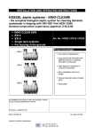
Department of Justice - Certificate of Accreditation Figure 1: Flow path Certificate of Accreditation On-Site Waste Water Management System This Certificate of Accreditation is hereby issued by the Minister for Justice and Workplace Relations pursuant to Section 59(2) of the Building Act 2000 and Part G2 of the Tasmanian Plumbing Code. System: Taylex ABS (Advanced Blower System) AWTS Manufacturer/ Taylex Industries Pty Ltd Supplier: ABN 35 113 453 091 Of: 56 Prairie Rd, Ormeau, QLD 4208 This is to certify that the Taylex ABS (Advanced Blower System) Aerated Wastewater Treatment System (the system) as described in Schedule 1 and using chlorine disinfection, has been accredited as an on-site waste water management system for use in single dwellings within plumbing installations in Tasmania. This accreditation is subject to the conditions of accreditation and permitted uses specified in Schedule 2, and in accordance with the Tasmanian Plumbing Code 2006. Dale Webster Director of Building Control Delegate of the Minister for Justice and Workplace Relations Date of Issue: 21 April 2011 Certificate No: BSR0603/2011 Change of company name and address; certificate re-issued 25 October 2013 This Certificate of Accreditation is in force until 20 April 2016 Page 1 of 16 Department of Justice - Certificate of Accreditation BSR0603/2011 SCHEDULE 1: Specification Taylex ABS (Advanced Blower System) Aerated Wastewater Treatment System General Description The Taylex ABS (Advanced Blower System) (‘the system’) collects and treats domestic wastewater. For treatment system schematic drawings and flow path, refer to Appendix A. For Engineering drawings refer to Appendix B. For treatment system components list refer to Appendix C System Components (refer to Appendix C for specifications of both the concrete and the polyethylene tank options). Capacities of the polyethylene tank are very similar to those of the concrete tank described below: One 9320 L vertical-axis pre-cast reinforced concrete cylinder containing: A 1684 L primary anaerobic chamber; A 842 L second anaerobic pre-treatment chamber with the outlet fitted with a Taylex disk filter; A 2071 L aeration chamber containing a Taylex 225 bubble air diffuser situated below fixed PVC plastic Media Substrate which has a surface area of 80 m² for biomass accumulation; An Air Blower which operates at 80 L/minute; High level float switches; A 662 L clarifying and sedimentation chamber; A Sludge Recirculation System in the Clarifier Chamber is constructed of 25mm and 15mm P.V.C pipe and operated by the Air Blower. A 621 L effluent storage chamber housing a 300 L chlorine contact tank and a Davey D25 submersible irrigation pump; Control module; and An audio-visual alarm system. Energy consumption Estimated Electricity Usage for a 4 person household with average wastewater flows and loads: Electrical Equipment Watts Daily operation kWh/year Estimated (hours) ~Annual Cost @ ~$0.20/kWh Nitto Blower 86 16 502 $100 Davey D25 irrigation pump 390 0.6 85 $17 Date of issue: 21 April 2011 Director, Building Control delegate of Minister for Workplace Relations Page 2 of 16 Department of Justice - Certificate of Accreditation BSR0603/2011 Description of Treatment Processes Wastewater enters the primary chamber where the bulk of the organic and inorganic solids are retained, by either settling to the bottom of the chamber or floating to the surface. The clarified sewage flows into a second anaerobic settling chamber before passing through the Taylex disk filter into the aeration chamber. Organic material in the wastewater is consumed primarily by anaerobic microbes in the first two chambers and by aerobic microbes in the aeration chamber. The 80 litre per minute Blower forces air through an air diffuser which is centrally located 300mm above the base of the aeration chamber. This supplies oxygen to aerobic microbes in the biomass suspended in the water and attached to the fixed Media Substrate. The Blower is preset to operate continuously when commissioned. This is reviewed at the first service and may be reduced in blocks of ten minutes to a minimum of thirty minutes on and thirty minutes off. This enables the aeration time to optimally match the organic loading. The biologically treated water flows from the aeration chamber through a 100mm P.V.C junction into the clarification chamber to allow settling of suspended particles to occur. A sludge return pipe located in the clarification chamber is activated during servicing to transfer accumulated settled sludge back to the primary chamber for further treatment. The clarified effluent is then disinfected as it flows over chlorine tablets into the effluent storage chamber (pump-well). A ball bearing float switch attached to the pump triggers the irrigation pump to periodically discharge the effluent to the irrigation field. A high-level alarm located in the pump well detects high water levels. The primary tank is de-sludged every three years or as deemed necessary by the service agent. The treatment plant is fitted with a control panel containing a programmable logic controller (PLC). The treatment system can be switched to the power saving mode, when no sewage flows are generated for an extended period of time (e.g. holidays). In this mode, aeration is reduced to the minimum required to supply the microbes with oxygen to ensure they remain viable. The system is designed for domestic waste water flows in accordance with AS/NZS 1546.3 and is capable of achieving a BOD5 less than or equal to 10 g/m3 and a TSS less than or equal to 10 g/m3 if required. Date of issue: 21 April 2011 Director, Building Control delegate of Minister for Workplace Relations Page 3 of 16 Department of Justice - Certificate of Accreditation BSR0603/2011 Schedule 2: Conditions of Accreditation 1.0 Definitions In this schedule: AS/NZS 1547 means the Joint Australian/New Zealand Standard ‘AS/NZS 1547:2000 On-site domestic-wastewater management’; AS/NZS 1546.3 means the Joint Australian/New Zealand Standard ‘AS/NZS 1546.3:2001 On-site domestic wastewater treatment units, Part 3: Aerated wastewater treatment systems’; AS/NZS 3000 means the Joint Australian/New Zealand Standard ‘AS/NZS 3000:2000 Wiring rules’ AS/NZS 5667 means the Joint Australian/New Zealand Standard ‘AS/NZS 5667.1:1998 Water quality – Sampling, Part 1: Guidance on the design of sampling programs, sampling techniques and preservation and handling of samples’; BOD5 means ‘5-day Biochemical Oxygen Demand’; Council means ‘the Municipal Council having jurisdiction’; Commissioned means ‘when the test results from a NATA Certified Laboratory show that the water quality requirements for the AWTS have been met and all pre-commissioning tests have been carried out in accordance with AS/NZS 1547 on all associated equipment and the subsurface irrigation system’; Designer means ‘a person who has a specialty in the area of designing on-site waste water management system installations and may include but not be restricted to appropriately trained professional engineers, soil scientists, land surveyors and plumbers’; Director means ‘the Director of Building Control’; EC means electrical conductivity E. coli means ‘Escherichia coli of the family Enterobacteriaceae which is a bacterium used in public health as an indicator of faecal pollution’; g/m3 means grams per cubic metre Manufacturer means ‘Taylex Industries Pty Ltd’; N means ‘Nitrogen’; NATA means ‘National Association of Testing Authorities’; PCA means ‘Plumbing Code of Australia 2004’; Permit means ‘a Permit issued by the council pursuant to section 82 of the Building Act 2000’; Permit authority means ‘a person or body authorised for that purpose by the council of the municipal area in which the on-site waste water management system is installed’; Supplier means ‘the party that is responsible for ensuring that products meet and, if applicable, continue to meet, the requirements on which the certification is based.’ The supplier for the Taylex Advanced Blower System is Taylex Industries Pty Ltd’ System means ‘Taylex ABS (Advanced Blower System)’ TPC means the ‘Tasmanian Plumbing Code 2006’. TSS means ‘Total Suspended Solids’. Date of issue: 21 April 2011 Director, Building Control delegate of Minister for Workplace Relations Page 4 of 16 Department of Justice - Certificate of Accreditation BSR0603/2011 2.0 General 2.1 The system must be supplied, constructed and installed in accordance with the design submitted and accredited by the Director. 2.2 The system must not be installed in a plumbing installation other than in accordance with the conditions of permit issued by the Permit Authority. 2.3 Each system must be permanently and legibly marked on a non-corrosive metal plaque or equivalent, attached to the lid with the following information: 2.4 The brand and model name or designation of the system; The manufacturer’s name or registered trademark; Top load limitations; and The month and year of manufacture. The supplier must supply the owner and occupier, of each installation, with a user manual setting out the following: (a) (b) (c) (d) (e) the treatment process; procedures to be followed in the event of a system failure; emergency contact number; care, operation, monitoring and maintenance requirements; and inspection and sampling procedures to be followed as part of the on-going monitoring and program required by the permit authority. 2.5 Any proposed modifications to the system’s specified processes, equipment, materials, fittings or manuals must have prior authorisation in writing from the Director and may be subject to additional verification or testing. 2.6 Each application to a permit authority to install a system must be accompanied by a siteand-soil evaluation report and design report in accordance with AS/NZS 1547 as appropriate. 2.7 The supplier must provide the following information to each permit authority where it is intended to install a system in their jurisdiction: Statement of warranty Statement of service life Quality Assurance Certification Installation Manual Service Manual Owner’s Manual Service Report Form Engineering Drawings on A3 format Detailed Specifications Certificate of Accreditation and Schedules. 2.8 This Certificate of Accreditation is valid for five (5) years from the date of issue or until withdrawn by the Director. 2.9 At each anniversary of the accreditation date the supplier must submit to the Director a list of all systems installed in Tasmania during the previous 12 months. The Director may randomly select up to 10% of the installed systems from each year of installation. The Director will notify the supplier’s nominated NATA accredited laboratory which systems are to be sampled and tested for BOD5 and TSS and Chlorine residual. The sampling and Date of issue: 21 April 2011 Director, Building Control delegate of Minister for Workplace Relations Page 5 of 16 Department of Justice - Certificate of Accreditation BSR0603/2011 testing of the selected systems is to be done at the supplier’s expense. The following results must be reported to the Director: Address of premises; Date inspected and sampled; Sample identification number; Chlorine Residual; BOD5; TSS; and Service history 2.10 Where a system has been found not to operate satisfactorily during its serviceable life, and as a result require modification to achieve the required water quality limits, all installed systems are to be modified accordingly. 2.11 When granting a permit the permit authority is to satisfy itself that the designer’s choice of the system configuration is optimal for the proposed use and site conditions. 2.12 The system must not be deployed to areas where seasonal climatic conditions will negatively affect its proper operation (refer to manufacturer’s specifications). 2.13 Prior to the granting of a permit to install a system the following reports must be submitted with an application to the permit authority: Site-and-soil evaluation report The site and soil evaluation report is to detail results of an assessment of the individual lot(s) for the public health, environmental, legal and economic factors which are likely to impinge on the location and design of a land-application system. (Refer to AS/NZS 1547 Clause 4.1.5 and associated appendices to 4.1). Design report The Design Report is to include the following: (a) Relevant aspects of the Site-and-soil Evaluation Report. (b) A report on the selection of the land-application system. (Refer to AS/NZS 1547, Clause 4.2.4 and associated appendices to Clause 4.2 for further information). (c) A report on the selection of the wastewater-treatment unit. (Refer to AS/NZS 1547, Clause 4.3.6 and associated appendices to Clause 4.3 for further information). (d) Sufficient information to show that the relevant performance requirements set out in the PCA have been met. (d) A loading certificate which sets out the design criteria and the limitations associated with use of the system and incorporates such matters as: (i) System capacity (number of persons and daily flow); (ii) Summary of design criteria; (iii) The location of and use of reserve areas; (iv) Use of water efficient fittings, fixtures, or appliances; (v) Allowable variation from design flows (peak loading events); (vi) Consequences of characteristics); changes in loading (due to varying wastewater (vii) Consequences of overloading the system; (viii) Consequences of underloading the system; (ix) Date of issue: 21 April 2011 Consequences of lack of operation, maintenance and monitoring attention; and Director, Building Control delegate of Minister for Workplace Relations Page 6 of 16 Department of Justice - Certificate of Accreditation (x) 2.14 BSR0603/2011 Any other relevant considerations related to the use of the system. The following reports must be submitted to the permit authority and owner and be made available to the Director upon request after commissioning of the system: Installation and commissioning report The Installation and Commissioning Report is to cover the ‘as-constructed’ records of the system installation together with the results of commissioning tests to demonstrate correct construction and installation and is to be provided to the owner and permit authority on completion of the work. (Refer to and AS/NZS 1547 Clause 4.5.6.3 and associated appendices to Clause 4.5). Inspection and Maintenance Report Maintenance reports cover ongoing inspection and maintenance operations in order to monitor the operation of the installation. (Refer to AS/NZS 1547 Clause 3.7.4 and associated Appendix 3A). 2.15 Where the supplied pump is not suitably rated for the proposed land application area it must be replaced with a pump which has a rated capacity that matches the hydraulic characteristics of the irrigation system and be capable of discharging at least 50% more than the 30 minute flow rate. For drip irrigation systems, ensure that drip emitter flow rates do not vary more than 10% from the design rate over the whole of the system when installed on a sloping site. Note: The pump selection is to be based on flow, head loss and pressure requirements. 2.16 Effluent distribution by sub-surface application may be permitted where the Permit Authority is satisfied that the application for a permit to install the system has demonstrated that the: (a) effluent can be retained within the authorised land application area; (b) where applicable the land application system has been designed and is capable of being installed and maintained in accordance with AS/NZS 1547; (c) the location of the land application system satisfies the relevant requirements of the State Policy on Water Quality Management 1997; and (d) the discharge is capable of satisfying the relevant water quality limits (see 5.7). 3.0 Installation and Commissioning 3.1 The installation and operation of the system must comply with the conditions of accreditation and the manufacturer’s instructions. 3.2 All plumbing work carried out in connection with the system installation must satisfy the requirements of the Building Act 2000, TPC and the Tasmanian Plumbing Regulations and be carried out by a registered plumber with appropriate training and qualifications. 3.3 All installations of the system must satisfy the installation requirements set out in Appendix A1 – On-site Waste Water Management Systems of the TPC. 3.4 All electrical work must be carried out by a licensed electrician and in accordance with relevant provisions of AS/NZS 3000. 3.5 The system requires a 240V AC power supply. A weather-proof isolating switch must be provided at the power outlet. The power supply must have its own clearly marked designated circuit breaker in the electricity supply fuse box. 3.6 Each system installation must be inspected and checked by the designer or the designer’s agent. The designer on completion is to certify that the system has been constructed, installed and commissioned in accordance with its design, the conditions of accreditation and any additional requirements set out in the permit. Date of issue: 21 April 2011 Director, Building Control delegate of Minister for Workplace Relations Page 7 of 16 Department of Justice - Certificate of Accreditation BSR0603/2011 Note: Where the designer is not available to supervise the installation the designer should obtain signed certification from the installing plumber stating that the installation has been constructed/installed and commissioned in accordance with its design, the conditions of accreditation and any additional requirements of the council and/or permit authority. 3.7 Where discharging wastewater to a land application system by irrigation, a lockable sampling tap or gate valve is to be provided on the outlet pipe to the irrigation system. 3.8 A report is to be prepared by the council approved plumbing contractor detailing the inspection of the installation and the results of the commissioning tests and be accompanied by a certificate certifying that the system is operating and performing adequately (see 2.15). 3.9 Copies of the following reports/certificates must be submitted to the council and the owner as soon as practicable after the commissioning of the system and after each scheduled or unscheduled service or inspection for the period specified in the permit: (a) The initial plant installation and commissioning report; (b) All required laboratory analytical test reports; and (c) All inspection and maintenance reports 3.10 Copies of any report or certificate required by the conditions of accreditation must be made available to the Director on request. 3.11 The designer is to provide a statement warning the user of which items and products that must not be placed in the system. 3.12 To verify that the plant is commissioned, sampling must be carried out, by a council approved person, for BOD5, TSS and Free Residual Chlorine. The samples are to be tested and reported on by a NATA certified laboratory. 4.0 Maintenance and monitoring 4.1 Each installation must be serviced and monitored at not less than 3 monthly intervals in accordance with the conditions of accreditation, the conditions of permit and manufacturer’s requirements. Notes: 1. Only a licensed plumber can carry out the maintenance and required monitoring of the system other than electrical work unless licensed to do so. 2. The licensed plumber may need to complete training by the supplier before carrying out any maintenance on the system. 3. The maintenance and monitoring intervals may be combined provided the monitoring frequency remains at 3 month intervals. 4.2 The owner of the system must enter into and maintain a maintenance contract with the council, the supplier of the system, or other council approved plumbing contractor. 4.3 The owner must enter into an agreement with the council to maintain the maintenance contract where that contract is with the supplier of the system or other council approved plumbing contractor. 4.4 The system must be operated and maintained to ensure it performs continuously and without any intervention between inspections carried out by the council approved plumbing contractor. 4.5 A service report is to be prepared by the plumbing contractor who carried out the work detailing the inspection of the installation and the results of all servicing tests and conditions at the completion of all scheduled or unscheduled services or inspections. 4.6 The service report is to be accompanied by a signed certificate certifying that the system is operating and performing adequately. Date of issue: 21 April 2011 Director, Building Control delegate of Minister for Workplace Relations Page 8 of 16 Department of Justice - Certificate of Accreditation BSR0603/2011 4.7 A copy of the service report and certificate is to be provided to the occupant and council. Each service report is to contain a statement reminding the user of which items and products that must not be placed in the system. 4.8 Each service must include monitoring the operation of the system and associated land application system. 4.9 Maintenance must be carried out on all mechanical, electrical and functioning components of the system as appropriate. 4.10 The monitoring, servicing and reporting of the installation must include but not be restricted to the following matters, as appropriate: (a) Reporting on weather conditions, ambient temperature, effluent temperature; (b) Odour; (c) Check and test pump (d) Check and test air blower, fan or air venturi and clean/replace air filters; (e) Check and test alarm system; (f) Check slime growth on membranes and report the on condition of membranes; (g) Check and report operation of sludge return, sludge level and de-sludging; (h) Check and record water meter reading (if fitted); (i) Check and record operation of irrigation area, irrigation fittings; (j) Check and clean/replace irrigation filters; (k) Check and report on water quality (testing for pH, Turbidity, EC and dissolved oxygen); (l) Check, and replenish chlorine disinfection system; (m) Cleaning of the following items at above the waterline– I. clarifier, II. pipework, III. valves IV. walls of chambers 5.0 Performance 5.1 Hydraulic and Organic Loading: The system is accredited for treatment of domestic wastewater from residential and commercial premises with the following MAXIMUM hydraulic and organic loads: Model Hydraulic load (L/day) Biochemical Oxygen Demand (g/day) Taylex ABS 2000 700 Treated effluent from the system must not exceed the following limits (90% of samples): For sub-surface irrigation: 5-day Biochemical Oxygen Demand (BOD5) Total Suspended Solids (TSS) For surface irrigation: 5-day Biochemical Oxygen Demand (BOD5) Suspended Solids (SS) E. coli Free Residual Chlorine concentrations Date of issue: 21 April 2011 3 3 3 3 20 g/m (max. 30 g/m ) 3 3 30 g/m (max. 45 g/m ) 20 g/m (max. 30 g/m ) 3 3 30 g/m (max. 45 g/m ) 10 cfu/100 mL (max. 20 cfu/100 mL) 3 3 ≥ 0.5 g/m and less than 2.0 g/m Director, Building Control delegate of Minister for Workplace Relations Page 9 of 16 Department of Justice - Certificate of Accreditation BSR0603/2011 6.0 On-going management 6.1 The mandatory servicing and monitoring is to commence 3 months after the plant is commissioned. The servicing and monitoring is to coincide with the supplier’s required ongoing routine scheduled maintenance program. 6.2 Where any systems have been found not to operate satisfactorily during their service life, and as a result require modification to achieve the required performance requirements, in particular, water quality limits, the installed systems are to be modified accordingly. 6.3 In the event of failure to comply with the water quality limits set out in these conditions, fortnightly sampling and testing for BOD5, TSS and Free Residual Chlorine must be carried out until the plant is re-commissioned. 6.4 The method of preserving and the handling of samples taken from the plant must satisfy the relevant requirements of AS/NZS 5667. 6.5 Copies of the following reports and certificates must be submitted to the permit authority and the owner as soon as practicable after the commissioning of the system and after each scheduled or unscheduled service for the period specified in the permit: (a) the initial plant installation and commissioning report (b) all laboratory analytical test reports; and (c) all inspection and maintenance reports 6.6 The system is to be de-sludged strictly in accordance with the manufacturer’s recommendations and the sludge is to be disposed of in accordance with the Tasmanian Biosolids Reuse Guidelines and the conditions of permit. 6.7 Only persons with a waste transport business Environment Protection Notice are to be engaged for the removal, transporting and disposal of accumulated sludge removed from the system. 6.8 Any waste material removed from the system must be collected and disposed of or utilised by an approved facility or agency. 6.9 Measures are to be put in place during servicing that will protect the environment, personnel and any other persons who could be affected by the activity. 7.0 Permitted uses 7.1 The effluent is suitable for land application by way of the following forms: (a) (b) sub-surface by: i. subsurface drip irrigation in accordance with the relevant provisions of AS/NZS 1547; ii. trenches, beds, mounds, evapo-transpiration systems in accordance with the relevant provisions of AS/NZS 1547; above ground by: i. spray irrigation ii. surface drip irrigation in accordance with the relevant provisions of AS/NZS 1547. Note: Each of the above forms of irrigation is subject to consent from the permit authority and the relevant provisions of AS/NZS 1547. 7.2 Where it is not practicable for effluent from the system to be applied in accordance with AS/NZS 1547 the method of discharge must satisfy contemporary relevant regulatory requirements to the satisfaction of the permit authority. Date of issue: 21 April 2011 Director, Building Control delegate of Minister for Workplace Relations Page 10 of 16 Department of Justice - Certificate of Accreditation BSR0603/2011 Appendix A Schematic drawings Taylex ABS Date of issue: 21 April 2011 Director, Building Control delegate of Minister for Workplace Relations Page 11 of 16 Date of issue: 21 April 2011 Director, Building Control delegate of Minister for Workplace Relations Page 12 of 16 Appendix B Engineering Drawings Date of issue: 21 April 2011 Director, Building Control delegate of Minister for Workplace Relations Page 13 of 16 Appendix C Component list and specifications 1) Tank (Concrete) Material: Height: Diameter: Total Volume: Working Volume: Dry Weight: Invert levels: Precast reinforced concrete in accordance with AS/NZS 1546.1:2008 2,350mm 2,400mm 9,320L 5,880L 6250k0067 1840mm and 1540mm 2) Tank (Polyethylene) Material: Polyethylene in accordance with AS/NZS 1546.1:2008 Height: 2,250mm Diameter: 2,204mm Total Volume: 8,584L Working Volume: 6,066L Dry Weight: 350kg Invert level: 1840mm 3) Taylex TFG Plate Filter Material: A.B.S, Nylon & 316SS Height: 400mm Diameter: 300mm Plates: 29 4) Nitto Air Blower LA80 Material: Alloy/plastic Height: 180mm Width: 200mm Length 300mm Weight: 4.9kg Capacity: 80L/min Pressure: 160 mbar Motor Power: 86 Watt Power Source: 240V/50Hz In addition to supplying the micro organisms in the bioreactor with oxygen, the blower is also used to supply air to the sludge lift using the “venturi principle”. 5) Irrigation Pump Height: 370mm Diameter: 225mm Weight: 9kg Capacity: ≤200L/min Head: 9m max Motor Power: 250 Watt Power Source: 230V/50Hz AC The irrigation pump is self controlled via a ball bearing activated float switch. When the triggering volume is reached in the pump chamber, the ball bearing in the float moves and Date of issue: 21 April 2011 Director, Building Control delegate of Minister for Workplace Relations Page 14 of 16 creates an active connection. The treated effluent is pumped to the approved dispersal zone. As the chamber level falls, the float drops and de-actives the pump. The type and capacity of pump will be in accordance with land application requirements, with the Davey D25A as standard supply. 6) Sludge Recirculation System Operation: Air Material: PVC This is a typical design for the trans-location of fluids using the “Venturi Principle”. Air is injected toward the base of a vertical open ended PVC pipe. Continuous displacement occurs as the air moves vertically to the liquid, drawing liquid through the open ended pipe base. The air/liquid mixture reaches a vertical maximum where it then moves through a 90° bend back into the primary pre-treatment chamber. The pipe is arranged in the base of the clarifier so that residual sludge constitutes the main vacuum target. The sludge recirculation system operates continuously and during servicing, the service agent fully activates the sludge recirculation system to remove built up sludge from the clarifier and return it to the primary pre-treatment chamber. 7) Control Panel Height: Length: Width: IP Rating: 100mm 160mm 60mm IP44 Provides direct electrical supply for the automatically operating submersible pump, audible and visual alarm, LCD display of function mode, adjustment and malfunction alarm, and programmable control of air blower. Active switching allows for sampling function of effluent, power failure indication and restoration, and circuit breaker protection. Also incorporates power saving function and alarm testing sequence. 8) Cover Box Material: Height: Width: Length HD Polyethylene UV protected 350mm 600mm 400mm 9) Alarm System High Water Float Switch Material: PVC Height: 50mm Width: 90mm Length 120mm Trigger: High Water Code: 3 Visual: Red L.E.D. and number 3 on panel Audible: Micro buzzer ≤ 10 dB 10) Alarm System Blower Failure Trigger: No or low air flow Code: 5 Visual: Red L.E.D. and number 5 on panel Date of issue: 21 April 2011 Director, Building Control delegate of Minister for Workplace Relations Page 15 of 16 Audible: Micro buzzer ≤ 10 dB 11) Bio Mass Material: Height: Width: Length: Surface area Food grade PVC 800mm 720mm 450mm 80m2 12) Air Diffuser Material: Height: Diameter: Weight: Type PVC, Santoprene & Nylon 35mm 220mm 350g Fine bubble Date of issue: 21 April 2011 Director, Building Control delegate of Minister for Workplace Relations Page 16 of 16