1
USER MANUAL
Version 3.7
Copyright and Trademarks
MaxWorkFlow 3.7 User Manual
Version 3.7 February 2003 Part number: MWF-3.7
Copyright © 1992-2003 Global Graphics Software Limited
All Rights Reserved. No part of this publication may be reproduced, stored in a retrieval system, or transmitted, in any form or by any means, electronic, mechanical, photocopying, recording, or otherwise, without the
prior written permission of Global Graphics Software Limited.
The information in this publication is provided for information only and is subject to change without notice.
Global Graphics Software Limited and its affiliates assume no responsibility or liability for any loss or damage that may arise from the use of any information in this publication. The software described in this book is
furnished under license and may only be used or copied in accordance with the terms of that license.
ScriptWorks is a registered trademark and Harlequin, the Global Graphics Software logo, EasyTrap,
FireWorks, FlatOut, Harlequin Color Management System, HCMS, Harlequin Color Production Solutions,
HCPS, Harlequin Color Proofing, HCP, Harlequin Full Color System, HFCS, Harlequin ICC Profile Processor,
HIPP, Harlequin Standard Color System, HSCS, Harlequin Chain Screening, HCS, Harlequin Dispersed
Screening, HDS, Harlequin Micro Screening, HMS, Harlequin Precision Screening, HPS, Harlequin Screening
Library, HSL, Harpoon, RipFlow, ScriptWorks MicroRIP, ScriptProof, ProofReady, SetGold, Scalable Open
Architecture RIP, SOAR, TrapMaster, TrapPro, PDF Creator and RIPFlow are all trademarks of Global Graphics Software Limited.
MAXRIP, MAXSmartScan, MAXQueuer, MAXOPI, MAXImposition, MAXPagePair, MAXPreps,
MAXTrapping, MAXColor, MAXPreCheck, MAXPDF Creator, MAXComposite, MAXEPS Optimizer,
MAXRasterDown, MAXQUE Central, MAXGIF, MAXTIF (CTP), MAXDCS2, MAXWinPrint, MAXFilmSave,
MAXRemoteClient, MAX-LE, MAXimum Output Options, MAXSplitter and MAXProofer are all trademarks
of Global Graphics Software Limited.
Portions licensed under U.S. Patents: Nos. 4,500,919, 4,941,038 and 5,212,546. EasyTrap is licensed under one
or more of the following U.S. Patents: Nos. 5,113,249, 5,323,248, 5,420,702, 5,481,379.
Adobe, Adobe Photoshop, Adobe Type Manager, Acrobat, Display PostScript, Adobe Illustrator, PostScript,
Distiller and PostScript 3 are either registered trademarks or trademarks of Adobe Systems Incorporated in
the United States and/or other countries which may be registered in certain jurisdictions.
ScenicSoft, the ScenicSoft logo, Preps, the Preps logo are either registered trademarks or trademarks of
ScenicSoft Incorporated.
Global Graphics Software Limited is a licensee of Pantone, Inc. PANTONE® Colors generated by ScriptWorks
are four-color process simulations and may not match PANTONE-identified solid color standards. Consult
current PANTONE Color Publications for accurate color. PANTONE®, Hexachrome®, and PANTONE
CALIBRATED™ are trademarks of Pantone, Inc. © Pantone, Inc., 1991.
Other brand or product names are the registered trademarks or trademarks of their respective holders.
US Government Use
The ScriptWorks software is a computer software program developed at private expense and is subject to the following Restricted Rights
Legend: “Use, duplication, or disclosure by the United States Government is subject to restrictions as set forth in (i) FAR 52.227-14 Alt III or
(ii) FAR 52.227-19, as applicable. Use by agencies of the Department of Defense (DOD) is subject to Global Graphics Software’s customary
commercial license as contained in the accompanying license agreement, in accordance with DFAR 227.7202-1(a). For purposes of the FAR,
the Software shall be deemed to be `unpublished’ and licensed with disclosure prohibitions, rights reserved under the copyright laws of the
United States. Global Graphics Software Incorporated, 95 Sawyer Road, Waltham, Massachusetts 02453.”
Contents
1
Getting Started
7
Introducing MaxWorkFlow™
Installing MaxWorkFlow 8
Starting MWF Manager 10
2
MaxWorkFlow Manager
7
11
MWF Manager tools 12
Manager options 14
Monitoring job processing in MWF 17
Module shortcut menus 18
Networking MaxWorkFlow 19
Saving and opening workflows 20
Importing and exporting workflows 20
Submitting jobs for processing 20
3
Example Workflow
4
SmartScan
21
27
SmartScan workflow 27
SmartScan controls 28
MaxWorkFlow 3.7 User Manual
1
5
Queuer
47
Queuer workflows 47
Queuer controls 49
6
BarCode
67
BarCode workflow 67
BarCode controls 68
7
Page Splitter
73
Page Splitter workflow 73
Page Splitter controls 74
8
Enabler
81
Enabler module workflow
Enabler controls 82
9
Harlequin RIP
81
87
Harlequin RIP workflow 87
Harlequin RIP controls 88
Harlequin RIP setup 89
Fonts Setup 100
Install ICC Profile 110
Creating a calibration profile 110
Harlequin RIP Viewer 118
10
OPI
119
OPI workflow 120
OPI controls 120
11
PreCheck
129
PreCheck workflow 129
PreCheck controls 130
12
Load Balancer
141
Load Balancer workflow 141
Load Balancer controls 142
2
MaxWorkFlow 3.7 User Manual
13
Down Sample
151
Down Sample workflow 152
Down Sample controls 152
14
Composition Server
157
Composition server workflow 158
Composition server controls 158
15
Imposition
163
Imposition workflow 163
Imposition controls 164
16
Pairs module
193
Pairs module workflow 194
Pairs module controls 194
17
Preps
209
Installation 209
Preps workflow 211
Preps controls 212
Preps setup 212
Preps Viewer 246
18
Media Saver
249
Media Saver workflow 249
Media Saver controls 250
19
TrapPro
253
The need for trapping 254
The TrapPro workflow 255
TrapPro controls 255
20
Optimizer
265
Optimizer workflow 265
Optimizer controls 267
MaxWorkFlow 3.7 User Manual
3
21
PDF Creator
281
PDF Creator example workflows
PDF Creator controls 283
PDF Creator options 284
Fonts in PDF Creator 299
PDF Creator Viewer 302
22
281
Common Controls for the Output Modules
307
Page set up options 308
Color management options 311
Halftone screening options 317
Calibration options 327
Color profile tab 332
23
TIFF
337
TIFF workflow 337
TIFF controls 338
24
GIF
349
GIF workflow 349
GIF controls 350
25
DCS
357
DCS workflow 357
DCS controls 359
26
CIP3
365
CIP3 workflow 366
CIP3 controls 366
27
Windows Printer
381
Windows Printer workflow 381
Windows Printer controls 382
28
HP Plotter
387
HP Plotter workflow 387
HP Plotter controls 388
4
MaxWorkFlow 3.7 User Manual
29
HP Printer
393
HP Printer workflow 393
HP Printer controls 394
30
Epson Printer
401
Epson Printer workflow 402
Epson Printer controls 403
31
Océ
411
Océ workflow 411
Océ controls 412
32
Max Imagesetter
417
Max Imagesetter workflow 417
Max Imagesetter controls 418
33
ECRM SCSI
425
ECRM SCSI Imagesetter workflow 425
ECRM SCSI Imagesetter controls 426
34
ULTRE SCSI Imagesetter
435
Ultre SCSI Imagesetter workflow 435
Ultre SCSI Imagesetter controls 436
MaxWorkFlow 3.7 User Manual
5
6
MaxWorkFlow 3.7 User Manual
1
1
Getting Started
1.1 Introducing MaxWorkFlow™
WELCOME to MaxWorkFlow™, the visual workflow design tool designed to
automate the prepress production process. With the MaxWorkFlow Manager
(referred to as MWF Manager in this manual) you use a simple to operate,
graphical workspace to create complex prepress workflows from over 20 processing modules which provide everything you need to create job processing
workflows, for example:
•
a Raster Image Processor (RIP) that uses the latest Harlequin RIP
technology, the acknowledged industry leader;
•
an incredibly fast and powerful in-RIP object-based trapping
solution;
•
output to high-resolution proofing devices and image setters;
•
workflow management tools that provide device load balancing,
multiplexing and reprocessing capabilities;
•
the ability to create PDF files, which are fast becoming the industry
standard for storing and distributing documents;
•
page splitting, imposition, source file optimization, downsampling,
composite proofing, OPI, and more…
MaxWorkFlow 3.7 User Manual
7
1
Getting Started
1.2 Installing MaxWorkFlow
MaxWorkFlow (MWF) is a Windows™ based application. Before attempting to
install MWF make sure your system meets the requirements listed in Table 1.1,
then proceed with the installation instructions that follow.
Component
Requirement
Processor
Pentium (600MHz or faster recommended)
Operating System
Intel Windows NT 4.0 Workstation* or Server, with SP6a
Windows 2000 Professional*, or Server, with SP2
Terminal Server 2000
* Server required to run services necessary for Macintosh
connectivity and FTP server
Minimum Disk space
500 MB free before installing.
For fast disk access a 4 GB fast ultra-wide SCSI disk is
recommended.
System memory
128 MB (256 MB recommended)
Network adapter
Ethernet 10 MB (Ethernet 100 MB recommended)
Applications
Internet Explorer 5.0 or greater
Imaging for Windows
Server services
Internet Information Server service
Macintosh services
TCP/IP printing
Clients supported
Windows 95/98/ME/NT4/2000/XP
Mac OS 8.1, 9.x or OS X
Table 1.1 MWF system requirements
1. Attach the supplied MWF security dongle to your computer.
2. Log on to Window as the administrator. This will ensure you have sufficient privileges to install MWF.
8
MaxWorkFlow 3.7 User Manual
1.2
Installing MaxWorkFlow
3. Insert the MWF installation disk. Open it in My Computer and doubleclick Setup.exe to start the MaxWorkFlow v 3.7 Setup wizard.
Figure 1.1 MaxWorkFlow v3.7 Setup wizard
4. Click Next in the wizard and follow the instructions in the wizard to
complete the installation procedure. You must provide a valid MWF
license file when prompted. The license file is provided on the floppy
disk supplied with MWF.
5. When asked if you want to remove module security, we recommend that
you click Yes. This will facilitate remote operations and will not compromise security on your computer or network.
Figure 1.2 Click Yes to remove module security during installation
6. To finish the installation procedure, click Finish to exit the installation
wizard.
MaxWorkFlow 3.7 User Manual
9
1
Getting Started
1.3 Starting MWF Manager
The MWF Manager is the main program window of MWF. It contains tools
and features which allow you to create digital prepress processing workflows,
and monitor the progress of jobs as they are processed with MWF. For a
detailed description of MWF Manager, refer to Chapter 2, “MaxWorkFlow
Manager” on page 11.
To start MWF Manager, click Start > Programs >MaxWorkFlow >
MaxWorkFlow Manager. Or double-click the MFW Manager icon added to your
Windows desktop, if you selected this option during the installation
procedure.
1.3.1 Starting the MWF from a command line
You can also start MWF from a command line. This allows you to enter additional parameters to control how the program starts. The command line
format is as follows:
man.exe [-c:filename.cfg] [-start] [-min]
where:
10
-c:filename.cfg
loads the specified workflow
-start
starts the workflow
-min
starts MWF minimized
MaxWorkFlow 3.7 User Manual
2
2
MaxWorkFlow Manager
MaxWorkFlow Manager (MWF Manager) is the main program window of
MWF. It provides all the tools that you will need to create your digital processing workflows and allows you to monitor the progress of your print jobs
as they progress along the workflow.
Figure 2.1 The MaxWorkFlow Manager
MaxWorkFlow 3.7 User Manual
11
2
MaxWorkFlow Manager
Jobs are processed in MWF by dropping modules onto the MWF workspace
and linking them together to form a logical processing workflow. Each
module has a set of options to control how jobs should be processed. Refer to
the relevant chapter in this manual for a description of each option in a
module.
2.1 MWF Manager tools
MWF Manager contains tools for creating workflows and configuring modules. Most of the tools remain inactive until you select a module on the workspace, then you can click a tool and use it to work with the module. Each tool
is described next.
Selector
This tool is used to select items on the workspace. Until you select a
module you cannot work with it. Click the tool then click the item that
you want to work with, or drag a selection box around the items if you
want to select more than one thing on the workspace.
Message Log
In MWF a message is generated whenever a module is placed on the
workspace, is started or stopped, processes a job, or issues an error. To
save these messages to a log file so they can be examined later, select the
module that you want to record and click the Message logging tool. The
location of the log file is determined by the Log file directory setting in
the Manager Options dialog box, as described on page 15. A small
icon appears beneath the module when message logging is enabled in
the module.
You may also access this command from the Modules menu, or press
Ctrl+L on your keyboard.
Link
Use this tool to link modules on the workspace to create workflows. The
Link tool will not allow you to link modules that would cause an illegal
operation in the workflow.
12
MaxWorkFlow 3.7 User Manual
2.1
MWF Manager tools
Change computer
This tool allows you to run the selected module on another MWF
installation. Jobs entering a module that has been configured in this
way are transferred to the remote MWF server where they are processed and returned to the originating server. See also Section 2.5 on
page 19 for more information on networking MWF.
You may also access this command from the Modules menu, or press F6
on your keyboard.
Delete
Use this tool to delete selected items on the workspace. Deleting a
module does not delete its associated folders; these need to be manually
removed from the server.
You may also access this command from the Modules menu, or press
Delete on your keyboard.
Setup
This tool is used to access a selected module’s setup dialog box, where
module options can be configured.
You may also access this command from the Modules menu, or press F5
on your keyboard
Pause
Use this tool to start and stop job processing in the selected module(s).
The button shows the current state of the selected module.
You may also access this command from the Modules menu, or press F2
on your keyboard to start or stop all modules on the workspace.
Auto Arrange
Use this tool to have MWF organize the modules that are on the
workspace. Depending on which tool is selected from the drop-down
list, the modules are automatically arranged in horizontal tree, vertical
tree or line tree alignment. A certain amount of experimentation may
be necessary to achieve the best layout with this tool.
MaxWorkFlow 3.7 User Manual
13
2
MaxWorkFlow Manager
You may also access this command from the View menu, or press F8 for
horizontal tree, F9 for vertical tree, or F10 for Line tree.
2.2 Manager options
MWF Manager has a set of options that control general settings for MWF. To
access these options, open the Manager Options dialog box, by selecting the
File menu and choosing the Options command, or by pressing F3 on your keyboard.
Figure 2.2 The MWF Manager options screen
The options are arranged into tabbed areas, each of which are described next.
2.2.1 Manager options: System tab
The System tab contains the following options:
Auto load last configuration
The last saved configuration is automatically loaded on the workspace
when selected.
14
MaxWorkFlow 3.7 User Manual
2.2 Manager options
Stop system if illegal link added
When selected the system stops all job processing if a link is added to the
workflow that causes an illegal link to be made. This option has little
effect since the Link tool itself will not allow an illegal connection to be
made.
Preview dpi
Allows you to specify the screen preview dpi (dots per inch) for image
files held by the Queuer. The default is set to 36 dpi, which is usually
adequate for most purposes. Should you require a higher resolution,
first try 72 dpi or 96 dpi since high resolutions take longer to process,
and consume more disk memory. The maximum allowed is 300 dpi.
Log file directory
Allows you to specify a location for the message log file MWF.LOG. Enter
the folder location directly into the text box, or click the
button and
navigate to the folder.
Maximum log file size
Allows you to specify a maximum file size for the log file MWF.LOG. When
the maximum file size is reached, the log file is discarded and a new one
is made.
Default measure unit
Allows you to choose the unit of measurement that you want MWF to
use.
2.2.2 Manager options: Desktop tab
The Desktop tab contains the following options:
Colors
The color options allow you to choose the colors used by MWF to display links, selected objects, progress bars and the desktop background.
The available colors are determined from your system settings; if you
wish to adjust these enter the Display Control Panel in Windows and
change the Color Palette to suite.
MaxWorkFlow 3.7 User Manual
15
2
MaxWorkFlow Manager
Show module name
When selected module names are shown for modules on the workspace.
This enables module to be readily identified.
Show status icons in modules
Select this check box to enable status icon on the workspace. Status icons
are used to indicate when message logging is enabled, or to indicate
when a module is configured for remote processing.
Icon size
Allows you to choose the default icon size for modules on the
Design palette.
Snap to grid
Enables the layout grid on the workspace, to which modules are aligned
as they are placed on the palette. You can adjust the grid spacing by
entering values in the two boxes, labelled Horizontal and Vertical.
2.2.3 Manager options: Network tab
The Network tab contains the following options:
Add
Click this button to add a remote MWF installation. Once a remote
installation has been added, its modules appear in MWF Manager and
they may be used in your workflows. Jobs entering a such a workflow is
processed on the remote server, then returned to the workflow. See also
Section 2.5 on page 19 for more information on networking MWF.
Remove
Click this button to remove a remote MWF installation. Once a remote
module has been removed, its modules no longer appear in the module
toolbar, however, any module in a workflow that has been added from a
remote MWF installation will still run on that server.
16
MaxWorkFlow 3.7 User Manual
2.3
Monitoring job processing in MWF
2.3 Monitoring job processing in MWF
When you have set up and started a workflow, it is often necessary to monitor
the processing of jobs to ensure everything is running smoothly and no errors
are occurring. MWF allows you to do this by providing each module with a
monitor window, like the one shown in Figure 2.3 below for the SmartScan
module.
To open the monitor window, select the module and choose View from the
Modules menu, or press F4 on your keyboard. The monitor window can also
be used to start and stop modules, and depending on the module that you are
monitoring, can be used to release jobs or reprocess them. The module chapters contain details about the controls available in the monitor.
Figure 2.3 SmartScan monitor window
MaxWorkFlow 3.7 User Manual
17
2
MaxWorkFlow Manager
2.4 Module shortcut menus
Frequently used module commands may be accessed by right-clicking a
module and choosing the appropriate command from a shortcut menu.
Figure 2.4 Module shortcut menu
Although each module uses a different shortcut module, certain commands
are common throughout:
Setup
Can be used to open a module’s setup screen where
module options can be accessed.
View
Can be used to open the module monitor window.
Clear Error
Can be used to clear an error which may have stopped a
module from processing.
Launch module
Can be used to restart a module that has been shut
down on the workspace. Modules that are shut down
appear disabled on the workspace.
Change computer
Can be used to select a remote installation of MWF that
will process jobs entering the module.
Delete
18
Can be used to delete a module and remove it from the
workspace.
MaxWorkFlow 3.7 User Manual
2.5
Networking MaxWorkFlow
2.5 Networking MaxWorkFlow
MWF is a powerful, server based application that is used to process jobs in a
digital prepress environment. MWF exerts a heavy processing workload on
the server, and, at times of increased workload, you may notice a degeneration
of throughout.
To increase job output, MWF may be networked to other MWF servers to
share job processing. Modules on the workspace can then be configured to run
on these remote installations, freeing the resources of the central server to process other jobs. Completed jobs are returned to the central server, where processing continues.
To link two or more installations of MWF, the following conditions must be
met:
1. MWF must be installed on all machines with a dongle and a license file.
See Section 1.2 on page 8 for information on installing MWF.
2. Each installation of MWF must be visible in the Window’s Network
Neighborhood.
3. COM security must be disabled on each installation. Select this option
during the MWF installation process.
4. Choose a MWF installation to act as the central, “master” server. This
machine runs the processing workflows and distributes jobs to your
other “secondary” MWF machines. Install MWF on your secondary
machines but do not have the MWF Manager running as this will cause
problems when you try to connect.
Once these conditions have been satisfied, select the module that you want to
configure and press F6 on your keyboard. In the Select computer window,
choose the remote MWF installation and click OK. When you have done this,
the workspace module appears with the
icon, and on the remote MWF
machine an icon for the running module appears in the status area of the
taskbar.
MaxWorkFlow 3.7 User Manual
19
2
MaxWorkFlow Manager
2.6 Saving and opening workflows
After creating a workflow it is a good idea to save it to disk so that it can be
recalled at a later date. When saving a workflow, you save the workspace configuration, which includes all the modules and links that are present on the
workspace, as well as all the module settings.
To save a configuration, click the Configuration menu and choose Save, or Save
as to save a previously saved configuration with another name. Please note
that saved workflows cannot be used on other installations of MWF. To do
that you must use the export/import tools, as described in Section 2.7 below.
To open a saved workspace configuration, click the Configuration menu and
choose Open. Before opening, the workspace will be cleared and you will be
prompted to save any unsaved configurations.
2.7 Importing and exporting workflows
MWF allows you to import and export workflows so they can be used on
other installations of MWF. An imported workflow contains all the modules,
links and module options from the original configuration.
To export a configuration, click the Configuration menu and choose Export. To
import a configuration, click the Configuration menu and choose Import.
2.8 Submitting jobs for processing
Jobs can be submitted to MWF using either a MWF Virtual printer, or through
a MWF shared folder. Use a virtual printer when you want to process a page
from an application, such as QuarkXPress™. Use a shared folder when you
have a job in the form of PS, PDF or EPS that has already been created with a
MWF printer correctly configured for the eventual output device.
Both these methods of submitting jobs require you to configure the SmartScan
module to create the MWF printer and shared folder. Once this has been done,
clients running document creating applications can use these resources to
submit jobs directly to MWF for processing. For more information on creating
g virtual printers and shared folders, refer to Section 4.2.1.2 on page 31 and
Section 4.2.1.3 on page 34.
20
MaxWorkFlow 3.7 User Manual
3
3
Example Workflow
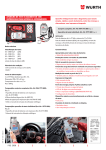
To help you get started with MWF—and to show you how easy it is to create
workflows—follow the instructions in this section to set up the example workflow shown in Figure 3.1.
Figure 3.1 The example workflow
MaxWorkFlow 3.7 User Manual
21
3
Example Workflow
In the example workflow, jobs are received into the workflow and passed
through the Optimizer module, which optimizes it for output and adds a lowresolution screen preview file into the job for OPI purposes. The job is then
passed to the Harlequin RIP module which passes it to the TrapPro module
for trapping, before rasterizing the page. Lastly, the page is output to an imagesetter and a TIFF image is created to provide a record of the page. Queuer
modules are used in the workflow to facilitate job flow, and to hold jobs before
being output to an imagesetter.
Step 1: Place and link modules on the workspace
1. Start by clearing the workspace. From the Configuration menu choose
New. If prompted by MWF, save the existing workflow on the workspace
if needed.
2. Place a SmartScan module on the workspace. Click the SmartScan
module in the Module toolbar, as shown in Figure 3.2, and then click on
the workspace to place the module.
SmartScan module
Figure 3.2 The SmartScan module
3. Place the other modules that comprise the workflow on the workspace,
these are: Queuer (2), Imposition (1), Harlequin RIP (1), TIFF (1), Ultre
SCSI Imagesetter (2). Arrange the modules on the workspace using
Figure 3.1 as a guide.
22
MaxWorkFlow 3.7 User Manual
4. Create the workflow by linking the modules. Click the Link tool to select
it. Click the first module in the workflow (the SmartScan module), and
then click the second module (the Queuer module) to create a link.
Link tool
Figure 3.3 The Link tool
5. Complete the workflow by creating links between the other modules.
Link the modules as follows:
SmartScan 1
Queuer 1
Queuer 1
Optimizer 1
Optimizer 1
Harlequin RIP 1
Harlequin RIP 1
TrapPro 1
TrapPro 1
TIFF 1, Queuer 2
Queuer 2
Ultre SCSI Imagesetter 1,
Ultre SCSI Imagesetter 2
6. To tidy up your workflow, click the Auto Arrange tool’s drop-down menu
and select one of these options: Horizontal Tree, Vertical Tree, or Line Tree,
depending on your particular preference.
Auto Arrange tool
Figure 3.4 The Auto Arrange tool
MaxWorkFlow 3.7 User Manual
23
3
Example Workflow
7. Lastly, enable module message logging in the Harlequin RIP module.
Although this has no effect on job processing, it is sometimes worthwhile capturing messages to monitor job processing, especially if jobs
are failing to be processed correctly.
To enable message logging, select the Harlequin RIP module and click
the Message Log tool. When you have done this, a small icon will
appear beneath the module to indicate that message logging is enabled
for that module.
Message Log tool
Figure 3.5 The Message Log tool
Step 2: Configure the modules
To produce the correct output, it is necessary to configure each modules in the
example workflow. To access a module’s options screen, right-click the
module and choose Setup from the shortcut menu. The instructions that
follow tell you how to configure the example workflow. Only those options
which need changing from their default setting have been specified—for the
purpose of this tutorial, most of the settings have been left at the defaults, but
you may wish to enter your own settings depending on your requirements.
1. Configure the SmartScan module as follows:
General tab:
•
24
Select all destination module check boxes.
MaxWorkFlow 3.7 User Manual
Virtual printers tab:
•
Select the Windows printer check box.
•
In Printer name type MWF Ultra94.
•
that is adjacent to PS Printer drivers, to
Click the Explorer button
open the PS Printer Drivers List screen. Click New to open the New
Printer Driver dialog box, then click the Explorer button to open the
Select file for new printer drivers dialog box. Select Ultre_9.ppd
from the list and click Open. Enter Ultra_94 in the Driver Name text
box. Click OK to close the New Printer Driver dialog box, and then
click Close to close the PS Printer Drivers List
Figure 3.6 New Printer Driver dialog box with correct settings
•
From the PS printer drivers list, choose the newly created Ultra_94
driver.
•
Click OK to close the SmartScan Setup dialog box.
2. Configure the Optimizer module as follows:
General tab:
•
Select EPS (Preview) from the Format options.
•
Click OK to close the Setup for Optimizer dialog box.
3. Configure the TrapPro module as follows:
•
Select TrapPro from the Trapping method option. Note that you may
need to enter a password to enable this feature.
•
Click OK to close the Setup TrapPro dialog box.
MaxWorkFlow 3.7 User Manual
25
3
Example Workflow
4. Configure the Queuer 2 module as follows:
•
To hold output for the devices until jobs are manually released or
they are deleted, in the Hold device list select the check boxes for
Ultre SCSI Imagesetter 1 and Ultre SCSI Imagesetter 2.
•
Click OK to close the Queuer setup dialog box.
Step 3: Process jobs
1. To process jobs the modules in a workflow must be started. The easiest
way to do this is to press F2 on you keyboard.
2. In your page generating application, such as QuarkXPress, open a page
that you want to process with MWF.
3. Print the page with the MWF Ultra94 printer. Note that if you are printing the page from a client machine, that is, one that sends jobs for processing, you will need to add the MWF Ultra94 printer to your list of
installed printers. See Section 2.8 on page 20 for more information.
Step 4: Save the configuration
To save your new configuration, choose Save from the Configuration menu.
Enter a name and a location for the configuration, and then click Save.
26
MaxWorkFlow 3.7 User Manual
4
4
SmartScan
The SmartScan module accepts jobs into the workflow for processing. It monitors a scan directory and filters jobs before passing them on for further processing by the workflow.
4.1 SmartScan workflow
The SmartScan module is always the first module in a workflow since it’s role
is to receive jobs into the workflow for processing. SmartScan accepts PostScript® language files (PS and EPS), PDF documents and TIFF images.
MaxWorkFlow 3.7 User Manual
27
4
SmartScan
4.2 SmartScan controls
Right-click the SmartScan module to display a pop-up menu showing all the
configuration and viewing options:
Figure 4.1 SmartScan pop-up menu
The following controls are available for the SmartScan module:
•
Setup—This provides all the options required to create and config-
ure the module. For more information see Section 4.2.1, “SmartScan”.
•
Create rulers test—Use to calibrate vertical spacing on your output
device. For more information see Section 4.2.2, “Create rulers test”.
•
Insert from—This option allows you to sweep jobs from another
folder into the SmartScan module. For more information see
Section 4.2.3, “Insert from”.
•
View—Choose this option to open the SmartScan Viewer, see
Section 4.2.4, “SmartScan Viewer” for more information.
See “Module shortcut menus” on page 18 for details on the other general
options in the pop-up.
4.2.1 SmartScan
To configure the SmartScan module choose Setup from the module pop-up
menu or select the module and press F5. The SmartScan Setup dialog box
opens. The options available are described in the following subsections.
28
MaxWorkFlow 3.7 User Manual
4.2
SmartScan controls
4.2.1.1 General
Figure 4.2 General tab
Module name
Allows you to enter a new name for the module. The name is used wherever the module is referenced: on the workspace; in log files; when linking to and from other modules.
Scan directory
Enter the location of a folder to accept incoming jobs, referred to as the
Scan directory. MWF is able to process PostScript language files, PDF, EPS
and TIFF images. Files that are not of these types are dealt with according to the error policy in force, which is defined in the Additional tab of
the Setup dialog, described in “Error policy” on page 31.
Backup directory
After processing jobs in the Scan directory files are automatically deleted
to save disk space. If you want to keep copies of the jobs then you can
specify the location of a backup folder in the Backup directory text box.
MaxWorkFlow 3.7 User Manual
29
4
SmartScan
Destination modules
After clicking this button all destination devices connected to the
SmartScan module are listed in the window. Destinations include physical devices such as printers, imagesetters and plotters, as well as file
format devices such as TIFF, GIF, DCS and PDF distillers. From the list,
select the check box(es) that jobs will be directed to when they enter the
SmartScan module.
Work Flow Paths
After clicking this button all workflow paths connected to the SmartScan
module are listed. From the list, select the workflow path that you want
jobs to follow when being processed.
File mask
Allows you to select which jobs will be processed according to the job
file name. Only jobs which match the file mask will be passed on for processing. The drop-down menu contains several commonly used masks
for filtering prepress files. You can also add you own mask by typing
directly into the text box. You may also use the wildcards (*) and (?),
which respectively represent zero or more characters in a string of characters, and any character at that position. For example:
*.*—all files matched
*.ps—only files with extension .ps matched
xyz.*—files called xyz with any extension matched
xyz*.*—matches files starting with xyz (for example, xyz123.ps)
??z*.*—matches files whose 3rd character is z (for example, xyz123.ps)
File type
This option allows you to accept jobs into the workflow according to file
type. SmartScan is able to distinguish different file types based on information contained in the job. This option is useful for jobs submitted by
Macintosh clients, which may not carry an extension to identify the file,
for example
.tif, .eps, .pdf.
30
MaxWorkFlow 3.7 User Manual
4.2
SmartScan controls
4.2.1.2 Additional
Figure 4.3 Additional tab
Error policy
Determines the action to take when an error file is encountered in the
workflow. There are three options to choose from:
Pause scan module on error
Processing is halted until the error file is deleted and
the module is started again.
Delete error file and continue work
The process is not interrupted but the error file is lost.
Move error file to error directory
The file is moved to MWF_Data\Input\Scan<x>\Error
and processing continues.
MaxWorkFlow 3.7 User Manual
31
4
SmartScan
Enable RST to PS Conversion
This feature encapsulates raster data (TIFF) with a PostScript language
wrapper, producing a binary data file that can be processed by the RIP.
This feature is enabled by default.
Use Ascii (for convert TIFF to PS)
Select this check box if you wish to convert TIFF file(s) to PostScript language files in ASCII format. This option is mainly used for (older) systems that cannot handle binary data.
Auto rotate Creo .PRV raster files
Select this option when it is necessary to rotate output files originally
generated by Creo systems.
File stabilize time
Allows you to set a delay before files entering the scan directory are sent
for processing, that is, before the job is passed to the next module in the
workflow. This delay is necessary to ensure that all data has been written
to disk before MWF attempts to read it. The default delay is 3 seconds,
but you may wish to increase this depending on the job file size, or the
latency factor inherent in your system (network speed, disk access time,
and so on).
This feature is particularly useful when submitting files to the spool folder via
an FTP process. If the SmartInput module tries to pick up a file for processing,
before the FTP program has fully released it, the file may become damaged, or
the workflow rendered inoperable. If you are using FTP, we suggest that you
increase the File stabilize time to 10 or 15 seconds, which will allow the FTP
program ample time to fully release the job to the input folder.
Custom PS comments
Use this scrollable window to append comments or PostScript language
code to files entering the SmartScan hot folder.
32
MaxWorkFlow 3.7 User Manual
4.2
SmartScan controls
Buffer size
Reserves an area of system memory for the spooling of files by SmartScan. The recommended setting depends on the amount of memory
(RAM) in your PC:
•
128 Mb RAM set buffer to 2048 Kb
•
256 Mb RAM set buffer to 4096 Kb
•
512 Mb RAM set buffer to 8192 Kb
Queuer Job priority
Use this option to assign a priority number to jobs. The Queuer module
uses this number to determine job processing order—that is, jobs with a
high priority are processed before those with a low priority.
This option only works when a Queuer module is placed immediately
after the multiple SmartScan modules or is preceded by only a PreCheck
module. Modules such as the Optimizer and Page Splitter will discard
the priority information.
Use Config-Snap
This option allows you to dynamically change module settings according to which of the SmartScan modules in the workflow receives a job.
A‘config-snap’ takes a snapshot of the settings configured in each of the
workflow modules and saves them to disk.
Select Use Config-Snap and choose a saved config-snap from the Always
use Config-Snap drop down menu. When a job is received into the SmartScan module, SmartScan will update the workflow module parameters
using the selected config-snap.
Default DPI
Enter a default resolution to be used if the incoming file does not specify
a resolution. For example, some TIFF files created by digital cameras do
not specify a resolution. The default value is set at 72 dpi.
MaxWorkFlow 3.7 User Manual
33
4
SmartScan
Windows share
When selected, MaxWorkFlow creates a shared folder on the Microsoft
network. This folder is known as a hot folder and users may place PS, EPS,
PDF and TIFF files into it for processing. The hot folder name is defined
by Share name, which will be the name seen by users on your network.
Macintosh share and Share name
This option is the same as for Windows share and Share name, except in
this case the hot folder is published on an AppleTalk network.
Mac Share name
Enter the name of the hot folder as it will appear to Macintosh clients.
4.2.1.3 Virtual printers
The Virtual printers tab lets you create a network printer that allows clients to
send jobs directly to the workflow from an application such as Microsoft®
Word or QuarkXPress. The virtual printer generates the PostScript language
34
MaxWorkFlow 3.7 User Manual
4.2
SmartScan controls
file and places it in the scan directory, where it is picked up by the SmartScan
module and processed by the workflow. The controls in the tab are described
next:
Figure 4.4 Virtual printers tab
Mac printer
Select this check box to publish the MWF virtual printer on an
AppleTalk network. This allows Macintosh clients to submit jobs from
an application, directly to MWF, by printing to the virtual printer. The
virtual printer handles the PostScript language rendering process and
places the job in the scan directory.
Printer Name
Enter a name for the virtual printer that will be published on the AppleTalk network.
MaxWorkFlow 3.7 User Manual
35
4
SmartScan
PPD
Enter the location of the printer driver (PPD) used by the virtual printer.
The default location for the PPDs used by MWF is C:\MaxWorkFow\PPD\.
Depending on your installation, this location may contain several PPDs.
Your supplier will be able to advise you on the appropriate PPD to use
for the workflow you are setting up.
NT printer
Select this check box to publish the MWF virtual printer on an NT network. This allows Microsoft clients to submit jobs from an application,
directly to MWF, by printing to the virtual printer. The virtual printer
handles the PostScript language rendering process and places the job in
the scan directory.
Printer name
Choose a name for the MWF virtual printer and type it in the text box.
Printer shared name
If you want to publish the printer on your NT network, enter a name
that clients will see on the network when adding the printer, otherwise,
leave this field blank. It is usual to use the same name for the shared
printer as that used on the server, as specified in Printer name. However,
when choosing a name, do not use the same name as a shared folder as
this may problems.
If you have Windows 95/98 clients, the virtual printer name must not be
more than 8 characters and spaces are not permitted. This limitation
does not apply to Windows NT / 2000 clients, where you may use up to
50 characters, with spaces.
PS Printer drivers
This area lists the PostScript language printer drivers (PPDs) currently
installed. You must select one of these to use with your virtual printer, or
add another PPD to the list by clicking Create PS Printer Driver, and use
that instead. When selecting a printer driver, use the most appropriate
PPD for the workflow you are configuring. Contact your supplier if you
are unsure which PPD to use.
36
MaxWorkFlow 3.7 User Manual
4.2
SmartScan controls
Create PS Printer Driver
This button allows you to add a new PostScript language printer driver
and assign a name to it. The driver then appears in the list of PS Printer
drivers for you to choose.
Remove PS Printer driver
This button allows you to remove a printer from the list of PostScript
language printers installed. This operation does not remove the printer
from Windows, the printer is still available to choose.
4.2.1.4 Name Convention
Figure 4.5 Name Convention tab
The Name Convention tab lets you choose how to define your job naming
conventions. There are two basic options to choose from: set up your own
naming conventions; or, for TIFF files, use the Harlequin naming conventions.
MaxWorkFlow 3.7 User Manual
37
4
SmartScan
Using the Harlequin naming conventions
To use Harlequin naming conventions select the check box, Use default Harlequin RIP name convention for TIFF files. In general, the RIP names each file
within a folder uniquely by combining characters from some of the following
character strings:
•
The page number of the job
•
A stem—fixed or variable
•
The name of the separation
•
A sequentially increasing number
•
A suffix
If the combined length of these character strings is sufficiently long, the RIP
truncates the stem to stay within the maximum length of a file name on the
computer running the RIP or an optional tighter limit providing greater portability between different types of computers.
38
MaxWorkFlow 3.7 User Manual
4.2
SmartScan controls
Creating your own naming conventions
To set up your own naming convention rules select the check box,
Use name convention, then click Insert field to access the Field Attributes dialog
box, shown in Figure 4.6. Use the options in the dialog to set up naming convention rules.
Figure 4.6 Field Attributes dialog box
The Field attributes dialog box contains the following fields:
Field
Choose a tag name for the naming convention. There
are a number of predefined tags listed in the menu for
you to choose from, that are subsequently used in other
modules. You can also create your own tags by typing
directly into the text box.
Description
Enter a brief description for your rule to help identify
its purpose.
Type
Select the tag’s field type from the drop down menu.
Position
Select where extraction begins in the job name. For
example, From beginning begins extracting characters
at the start of the job name. You can also specify an
MaxWorkFlow 3.7 User Manual
39
4
SmartScan
offset character position to use in conjunction with Position, in which case extraction starts at the offset character position.
Size
Determine the overall length of the name convention
field by choosing from the following options:
Fixed
Choose this option when your name convention needs
to be of a certain fixed length.
Field complete when start next field
The size of the field is determined by the position at
which another rule starts. For example, if another rule
is setup to extract characters starting at position 10, then
the last character used for this rule would be character
9.
Field complete when start substring
Characters are extracted until the defined substring
(entered in the text box) is found. A common use of this
rule is to specify a substring of .ps or .tif so that
extraction stops when the job name suffix is reached.
Set
Characters are extracted until one of the values listed in
the set is found. For example, you can set up a list of
possible values - Cyan, Magenta, Yellow and Black for
files that have the color name in their name. Use Add
and Delete to manage the set list.
Field value translation
If you select this check box the Field translation dialog
box is opened and is used to map an extracted field
value to another value. For example, if the color of the
file is encoded in the filename as a number—1 for Cyan;
2 - Magenta; 3- Yellow, and so on—you can setup the
40
MaxWorkFlow 3.7 User Manual
4.2
SmartScan controls
translation table in such a way that those numbers
being extracted from the filename, will be translated
into the full color name.
When you have defined a rule you can test it to make sure it performs as
intended. In the list, highlight the rule and click the Test button. In the dialog
box that appears, locate the file to test and click OK. A pop-up dialog displays
the result of the test, which you can use to verify that your rule worked successfully.
Save your rules by clicking Save convention, specifying a name and location.
The other buttons in the Name Convention tab allow you to edit, delete, load
and clear your rules.
MaxWorkFlow 3.7 User Manual
41
4
SmartScan
4.2.1.5 ICC Input Profiles
International Color Consortium (ICC) profiles are industry-standard color
profile definitions that describe the output characteristics of printers, printing
processes, scanners, presses, and other equipment. The Harlequin RIP uses
the ICC profile to ensure a job is ripped according to the color characteristics
of the output device.
Figure 4.7 ICC Input Profiles tab
The options in the ICC Input Profiles tab are:
RGB
Choose the ICC input profile for RGB color separations.
CMYK
Choose the ICC input profile for CMYK color separations.
To implement ICC profiles you will also need to configure the Harlequin RIP
module, as described in “Install ICC Profile” on page 110, as well as the relevant output module, refer to the module’s chapter in this manual for details.
42
MaxWorkFlow 3.7 User Manual
4.2
SmartScan controls
4.2.2 Create rulers test
To test vertical and horizontal spacing on your output device you can create a
calibration page by choosing Create rulers test from the module pop-up menu.
The Rulers Generation dialog box opens, as shown in Figure 4.8.
Figure 4.8 Rulers generation dialog box for leading calibration
Y ruler length (cm)
Enter the length of the vertical ruler to be printed.
X ruler length (cm)
Enter the length of the horizontal ruler to be printed. You must select the
Create X ruler check box to enable this option.
Click OK to generate a calibration page that is sent along the workflow to
the output device—an example of a simple workflow, needed to create a
rulers test calibration on an imagesetter, is shown in Figure 4.9.
Figure 4.9 Example workflow to output rulers test calibration page
MaxWorkFlow 3.7 User Manual
43
4
SmartScan
4.2.3 Insert from
The Insert from option (available in the SmartScan pop-up menu, see “SmartScan controls” on page 28) allows you to add jobs from a folder into the
SmartScan module’s scan folder. For example, you may want to resubmit jobs
that have already been processed and stored in a backup folder, or submit jobs
from another folder as and when the need arises.
From the Select directory dialog box (Figure 4.10) choose a folder where the
jobs are located and click OK. It should be noted that files are not deleted from
the Insert from folder, as is the case when using a scan directory. Also, job files
which are not of the correct type, that is those that are not PostScript language
files, EPS, PDF or TIFF images, are simply ignored and are not sent for processing.
Figure 4.10 Select the folder to ‘Insert from’
44
MaxWorkFlow 3.7 User Manual
4.2
SmartScan controls
4.2.4 SmartScan Viewer
The SmartScan Viewer, shown in Figure 4.11, lists all SmartScan modules on
the workspace and shows the processing activity, log file and pause status of
each. There is also has a message log area where SmartScan messages can be
observed.
Figure 4.11 SmartScan Viewer
To open the Viewer window, double-click the SmartScan module, or rightclick it and choose View from the pop-up menu. To close the Viewer click Hide.
If you wish, you can detach the toolbar so that it floats on the desktop. Clicking Hide then shows/hides the module list, but leaves the toolbar visible. To
completely close the Viewer, drag the toolbar back to the Viewer then click
Hide.
From the Viewer you may start/stop SmartScan modules by selecting the relevant module and clicking Start/Stop in the toolbar You can also open the module’s setup dialog box by choosing System > Options.
MaxWorkFlow 3.7 User Manual
45
4
46
SmartScan
MaxWorkFlow 3.7 User Manual
5
5
Queuer
The Queuer has two primary functions in the prepress workflow:
•
it is used to hold jobs before they are sent to an output device so they
can be inspected, redirected, deleted or reprocessed.
•
it manages job flow between several alike devices so that each takes a
fair share of the output workload.
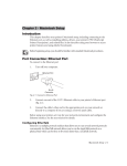
5.1 Queuer workflows
The Queuer accepts all types of job files as it is simply a place to hold jobs and
store them for future processing. Figure 5.1 illustrates two workflows involving the Queuer. In the uppermost example the Queuer is used to manage
output for two imagesetters, ensuring that jobs are shared equally between the
MaxWorkFlow 3.7 User Manual
47
5
Queuer
two devices. In the second example, the Queuer is used to hold jobs before
they are sent to an imagesetter for final output. The operator is able to view
the image file before it is printed, to ensure the image is satisfactory.
Figure 5.1 Queuer workflows
48
MaxWorkFlow 3.7 User Manual
5.2
Queuer controls
5.2 Queuer controls
Right-click the Queuer module to display a pop-up menu showing all the configuration and viewing options, Figure 5.2.
Figure 5.2 Queuer module pop-up
The following controls are available for the Queuer module:
•
Setup—This selection provides all the options required to create and
configure the Queuer, as described in Section 5.2.1, “Queuer setup”.
•
View—This provides a list of jobs which are currently held in the
Queuer, as well as a list of jobs which have already passed through
it. For details on the Viewer window see Section 5.2.2, “Queuer
Viewer”.
See “Module shortcut menus” on page 18 for details on the other options in
the pop-up menu.
MaxWorkFlow 3.7 User Manual
49
5
Queuer
5.2.1 Queuer setup
To configure the Queuer module, choose Setup from the pop-up menu to
display the Queuer setup dialog box, shown in Figure 5.3.
Figure 5.3 Queuer Setup dialog box
The dialog contains the following options:
Module Name
Allows you to enter a new name for the module. The module name is
used wherever the module is referenced: on the workspace; in log files;
when linking to and from other modules.
Storage directory
This option is used to set the folder location for jobs entering the Queuer
module. Files are held in the folder until they are deleted according to
the Delete policy setting, described below. The default location is set to
C:\MAXWORKFLOW\Storage (if you installed the application on the C:
drive), although you may enter your own location directly into the text
box, or by clicking the button to the right and navigating to a folder.
50
MaxWorkFlow 3.7 User Manual
5.2
Queuer controls
Multiplex
When this option is selected job output is distributed evenly between
connected output devices, ensuring that each device is used in turn.
Figure 5.4 shows an example workflow where a pair of imagesetters are
used to output ripped jobs. The Queuer module, set to multiplex, shares
the output between the two imagesetters, ensuring that both are used.
This feature only works with hardware devices that have a bi-directional
communication capability, examples of which include Highwater Cards,
LPT1, LPT2, and so on. This is not a software spooling function. The
option is not selected by default.
Figure 5.4 Multiplexed workflow
Copy Multiplex
This control has no function in this release of MWF. It will be implemented in a future release of the product.
Last job on top
When this check box is selected the latest job entering the Queuer is
placed at the top of the job list and is consequently released from the
Queuer prior to those jobs which entered before it. It should be noted
however, that jobs with higher priorities take precedence and will be
released before jobs with lower priorities. See Queuer Job priority on page
33 for details on determining job priority. This option is selected by
default.
MaxWorkFlow 3.7 User Manual
51
5
Queuer
Spool job before processing
When this option is selected the job is spooled to disk and allowed to stabilize before it is processed any further. This ensures that all of the job
file is present before processing commences. The disadvantage of selecting this option is that it may result in longer processing times, since the
module waits a short period for each file to be become stable. We therefore recommend that you select this option only if you are experiencing
spooling issues, which may result in damaged files.
Delete policy
Select an option to determine when files are removed from the Queuer
storage folder. This is an important factor to consider when setting up
your workflows. Disk space can quickly fill up when too many files are
retained, especially complex graphics that may themselves contain large
previews. MWF will shutdown any workflow where it is unable to
retain a file due to lack of storage space.
Choose from one of the following options:
Immediately after processing
Files are never saved in the storage folder, they are
deleted immediately after processing.
Keep nnn minutes
Files are retained for the specified period, after which
they are deleted.
Never (delete only manual)
Files must be manually deleted from the storage folder.
If you choose this option, ensure that your disk space
does not become overloaded before deleting files
manually.
Delete oldest file if free disk space < nnn MB.
Retain files until the stored files reach a disk space limit,
at which point the oldest files are deleted until the free
disk space is greater than the limit.
52
MaxWorkFlow 3.7 User Manual
5.2
Queuer controls
Generate preview for raster files
When selected, a preview image is generated for TIFF and EPS image
files entering the Queuer. The image preview may be inspected in the
Queuer Viewer, and appropriate action taken by the operator after
viewing. To facilitate this, turn on Hold devices for the output module
and the job will be held in the Queuer until it is released, deleted or
reprocessed by the operator.
The resolution (dpi) of the preview image is set in the System tab of
Manager options—refer to page 15 for more information on setting this
option.
Freeze when imagesetter is imaging
Select this check box to ensure that priority is given to an Imagesetter
module during data transfer to prevent data under run. It is not necessary to select this option if your imagesetter can automatically start and
stop in the case of data under run.
It should be noted that when this option is selected the Queuer does not
accept jobs, nor can it release jobs while the imagesetter is being written
to. Be mindful that this could seriously stall the workflow on a regular
basis. A solution to this problem is to set up a double Queuer workflow,
as shown in Figure 5.5. Connect Queuer 1 to the Imagesetter and
Queuer 2 to another output modules, such as a TIFF module. Set
Queuer 1 to Spool job before Processing so that it does not stall the pipe-
MaxWorkFlow 3.7 User Manual
53
5
Queuer
line between the RIP and Queuer 1 as the imagesetter starts to write.
This way it frees up the RIP to open the pipeline to Queuer 2 and allows
the RIP to write freely to it without interruption.
Figure 5.5 Workflow with double Queuer modules
Hold devices list window
Shows the list of output devices that are attached to the Queuer and is
used to select which devices should have their jobs held by the Queuer.
When the Multiplex option is selected, any devices selected are overridden by multiplexing.
Figure 5.6 Hold devices window
54
MaxWorkFlow 3.7 User Manual
5.2
Queuer controls
5.2.2 Queuer Viewer
The Viewer window, shown in Figure 5.7, shows jobs that are currently held,
pending release for when the destination module becomes available. The
Viewer also lists those jobs that have passed through the Queuer and have
been retained, possibly for re-processing at a later date. To open the Viewer,
right-click the Queuer module and choose View from the pop-up menu. Alternatively, press F4 on the keyboard.
The Viewer is split into two main areas: the upper area lists jobs that are currently waiting to be released from the Queuer; the lower area lists jobs that
have been processed, and which have been retained for possible future processing. These jobs are stored on the hard disk in the Storage folder, as specified in the Queuer setup dialog box, described in “Storage directory” on
page 50.
Figure 5.7 Queuer Viewer
Each job in the Viewer is listed with the following information:
Job Id
An identification number assigned to each job. Separated jobs (CMYK) are assigned the same id number,
since they are part of the same job.
MaxWorkFlow 3.7 User Manual
55
5
Queuer
Processing job and Passed job
The file name of the job. You may change the job name
by using the Change name tool, as described in “Change
names” on page 65.
Page
The page number of the job when the job consists of
multiple pages.
Color
The color designated from the final output specifications. For example, CMYK composites are Device
CMYK, monochrome separations are Cyan, Magenta,
Yellow, Black.
Date
Date the job was submitted to the Queuer module.
Time
Time the job was submitted to the Queuer module.
Type
File type for the job.
Size
Memory byte size of the job file.
Destination
Final destination output module for the job.
5.2.2.1 Viewer toolbar
The Viewer toolbar, shown in Figure 5.8, contains tools for manipulating jobs
listed by the Queuer. Some of the buttons in the toolbar are applicable to only
one of the lists (processing jobs or passed jobs) and consequently appear
dimmed when the tool is not available for a particular job
Figure 5.8 Viewer toolbar
The controls in the toolbar work on selected jobs as follows:
Hide window
Closes the Viewer window.
56
MaxWorkFlow 3.7 User Manual
5.2
Queuer controls
Go / Stop
This tool starts / stops the Queuer module. In MWF a module
must be started before it can process jobs. The button displays the
current go/stop status of the Queuer module; clicking the tool
switches the module to the alternative state, and the button icon
changes accordingly.
Reprocess selected jobs
Reprocesses jobs that have already passed through the Queuer, but
which have been retained for future processing in the passed jobs
list. The job is directed to the device as specified when the job was
originally submitted. If you want to redirect the job to a different
device, then you should use Redirect selected jobs, as described
next.
Redirect selected jobs
Redirects jobs that have been retained by the Queuer for future
processing (listed in the passed jobs area of the Viewer) to a different output device. From the Select destination devices dialog box,
shown in Figure 5.9, select the new output device and click OK.
The jobs are then moved into the processing jobs queue, where
they are subsequently released to the destination device.
Figure 5.9 Select a destination device
MaxWorkFlow 3.7 User Manual
57
5
Queuer
Abort jobs
Aborts jobs and removes them from the list of jobs waiting to be
processed. The jobs are also deleted from the hard drive, so they
must be resubmitted if they are required again.
Delete
Removes jobs from the passed jobs list and deletes them from the
storage folder.
Hold jobs
Holds jobs in the Queuer. Jobs may be subsequently released
using the Release jobs tool. A hand symbol
appears next to
any held job.
Release jobs
Releases held jobs from the Queuer. According to the delete policy
in force (see page 52), when a job is released it is either placed in
the passed jobs list, or it is removed from the Queuer and deleted
from disk.
Change job name
Changes the name of the selected job, listed in the Queuer. Click
the tool and enter the new job name in the dialog box that
appears.
Change job priority
Changes the priority of the selected job. In MWF, jobs are
released from the Queuer according to priority, so that a job with
priority 10 is released before a job with priority 0. Jobs are initially assigned a priority as they enter the SmartScan module,
configured in the Additional tab, as described on page page 31.
Compose files
Combines only selected CMYK separations into a composite
image, then shows the resulting image in the Preview window, as
shown in Figure 5.11, page 60. You can also use this tool to
“soft proof” individual separations. See also, Composed job preview below.
58
MaxWorkFlow 3.7 User Manual
5.2
Queuer controls
Note: This tool can only combine separations that have subsequently passed
through the Harlequin RIP module.
Compose job
Combines all CMYK separations for a job into a composite
image, then shows the resulting image in Preview window, as
shown in Figure 5.11. Similar in operation to the Compose files
tool, but you need only select one of the job separations to view
the composed job.
Custom preview generation
Creates a preview image of a selected separation at a particular
resolution. The resolution currently chosen is displayed above
the icon. To choose another resolution, click the arrow and choose
a resolution from the menu. To add an alternative resolution to
the menu, choose Custom DPI and enter a resolution in the Enter
DPI for Preview text box.
Search
Locates jobs in the Queuer according to some specified search criteria. The Search dialog box, shown in Figure 5.10, allows you to
search on any aspect of job detail—job id, page number, job size,
format type, and so on. Any jobs found matching the search criteria are highlighted in the Viewer.
Figure 5.10 Queuer Search dialog box
MaxWorkFlow 3.7 User Manual
59
5
Queuer
Show negative preview (Ctrl+N)
Previews images as negatives. When this option is selected, the icon
image is shown as a negative.
5.2.2.2 Preview window
The preview window can be used to view raster images and PostScript language files with embedded preview images for jobs that are listed in the
Queuer module. You can also preview a composite image by selecting the separated plates then clicking Composed preview. If there is a Harlequin RIP
module in the workflow, previews can only be generated in a pre-RIP Queuer
Viewer window if a post-RIP Queuer is also present in the workflow.
Figure 5.11 Preview window
60
MaxWorkFlow 3.7 User Manual
5.2
Queuer controls
The following controls are used in the previewer:
Saves the preview image to disk. Click the tool then specify a file name
and choose to save the image in either BMP or TIFF format. You can also
use the mouse to make a selection in the preview window and save the
selection by using the Copy item in the File menu.
Resizes the preview image to fit within the preview window. It is also
accessible by choosing Fit to best from the View menu.
Increases magnification of the image by zooming in with every click.
You can also zoom using the drop down zoom menu, which is located to
the right of the tools.
Decreases magnification of the image by zooming out with every click.
You can also zoom using the drop down zoom menu, which is located to
the right of the tools.
5.2.2.3 System menu
Start
This menu item starts the Queuer module allowing it to process jobs.
Options
Opens the Queuer Setup dialog box used to configure Queuer options
such as name, storage directory, hold devices and so on. This dialog box
is described in Section 5.2.1.
Spot colors
Choosing this menu item opens the Spot Colors window, as shown in
Figure 5.12. All spot colors present in your MWF system are listed, along
with their component color density values and a preview of the color. If
you want to change a spot color, click the CMYK value and enter a new
MaxWorkFlow 3.7 User Manual
61
5
Queuer
value directly into the text box. The spot color preview changes to reflect
the new value. The other controls available in this dialog box are
described next.
Figure 5.12 Spot Colors window
62
MaxWorkFlow 3.7 User Manual
5.2
Queuer controls
Add color
Use this control to add new spot colors to the list. In the Spot Color Editor
dialog box (Figure 5.13) enter a name for the new spot color and set percentage density values for each color component.
Figure 5.13 Spot Color Editor dialog box
You can also add spot colors by right-clicking the print job in the Queuer
Viewer window and choosing Add spot color from the pop-up menu. The spot
color name is taken directly from the name of the color plate.
Delete color
This button deletes a selected spot color from the list.
Find
Allows you to search the list for a spot color. Enter the name of the spot color
to dynamically search the list and highlight the spot color.
OK
Saves changes that you may have made and closes the dialog box.
Cancel
Click this button to dismiss the window without saving any changes that you
may have made.
MaxWorkFlow 3.7 User Manual
63
5
Queuer
5.2.2.4 View menu
The View menu allows you to show and hide areas of the Queuer Viewer.
Figure 5.14 shows the various parts of the window that can be toggled from
the View menu.
Preview window
Toolbar
Passed jobs
window
Processed jobs
window
Message Log
window
Figure 5.14 Queuer Viewer
5.2.2.5 Jobs menu
Reprocess
Reprocesses selected jobs from the Passed jobs list to the output module.
The passed jobs list shows jobs which are being kept in the storage folder
until they are deleted according to the delete policy setting, as explained
on page 52.
Redirect selected jobs
This option allows you to select an output device so that jobs which have
already passed through the module can be sent to another device. From
the list, choose the device you want to use for output and click OK. The
job will be reprocessed for the new output device.
64
MaxWorkFlow 3.7 User Manual
5.2
Queuer controls
Abort job
This option removes a job from the Process Jobs list that contains jobs
which are awaiting processing or are currently being processed.
Delete
This option removes a job from the Passed Jobs list and deletes the job
from the Storage folder.
Hold
This control stops a job from being sent to an output device after it has
been released from the Queuer.
Release
Releases selected jobs from the process jobs list and passes them to the
next module in the workflow. The job is then placed in the Passed jobs
list from where it can be resubmitted for further processing.
Change names
Allows you to specify a new job name for a selected job in the Queuer.
The new job name is used by subsequent modules in the workflow.
Change priority
Allows you to change the priority of a job so that its release order from
the Queuer module is changed. MWF releases jobs according to job priority, which is automatically determined by the SmartScan module as
explained on page page 33.
Composed preview selected files
Use this option to combine selected separations into a composite image
and then preview in the Preview window. Use your mouse and Ctrl key
to highlight the separations that you want to combine. You can also use
this option to soft proof individual separations.
Note: This feature only combines plates which are held in the Queuer
and have already passed through the Harlequin RIP module.
MaxWorkFlow 3.7 User Manual
65
5
Queuer
Composed job preview
Use this option to combine all plates in a job into a composite image and
then preview in the Preview window. You need only select a single separation to view all the separations in a job. If you want to view separations individually, then use the Composed preview selected files option.
Custom preview generation
Use this option to view the selected separation at the resolution set by
the Custom preview generation icon in the module toolbar, as described
on page 59.
Save as
Saves a copy of the PostScript language job.
Select all
Selects all files in a job list when one of the jobs are selected.
Search
Use the search tool to find specific jobs in the Process jobs list or the
Passed jobs list. You can search on any aspect of the job including name,
job id, page number, date, color and size.
Search again
Repeats the last file search.
Negative preview ON/OFF
Use this option to view all preview images as negatives.
66
MaxWorkFlow 3.7 User Manual
6
6
BarCode
The BarCode module accepts PostScript language and PDF files and adds a
barcode to the file before passing the job onto a RIP.
With this module you are able to specify the barcode type and configure its
size, rotation and position.
6.1 BarCode workflow
The BarCode module is typically placed between a SmartScan module and a
Harlequin RIP—it accepts and produces PostScript language and PDF files.
Figure 6.1 BarCode workflow
MaxWorkFlow 3.7 User Manual
67
6
BarCode
6.2 BarCode controls
Right-click the BarCode module to display the pop-up menu showing the configuration and viewing options:
Figure 6.2 BarCode pop-up
The following controls are available for the BarCode module:
•
Setup—see Section 6.2.1, “BarCode setup”.
•
View—see Section 6.2.2, “BarCode Viewer”.
See “Module shortcut menus” on page 18 for details on the other general
options in the pop-up.
68
MaxWorkFlow 3.7 User Manual
6.2
BarCode controls
6.2.1 BarCode setup
To configure the BarCode module select Setup from the pop-up menu.
Figure 6.3 BarCode module setup dialog box
This dialog provides access to various configuration options.
Module name
Allows you to enter a new name for the module. The module name is
used wherever the module is referenced: on the workspace; in log files;
when linking to and from other modules.
BarCode
The options in this section define the type of barcode and the information contained within the barcode.
Encoding
Selecting the drop down menu provides a number of
barcode options in all the common formats.
Encoded string
This text box is where you type in the specific information you want designed into the barcode. For instance
you could type in the date, job or customer ID number,
MaxWorkFlow 3.7 User Manual
69
6
BarCode
printing press number, or color information. Most of
the encoding languages allow only numbers whereas
languages such as code39 allow letters and symbols.
When you select an Encoding from the drop down
menu the required format of the Encoded string appears
below the text box. When creating a new string you
must closely follow the displayed format. For example,
in code39 strings you must only use capital letters
because lower case characters will cause the barcoding
to fail.
You should also be aware of the length of the string.
Many of the available options in the module specify
how long the string must be. Note that spaces are
counted as a character. If an encoding language (such as
UPC-A) specifies a certain number of digits, you must
make sure you have exactly that number of digits. An
encoding any shorter or longer will not produce a barcode. Code39 allows you to have a variable length barcode however there is a limitation on the length.
Although it is not practical to make the barcode (in
code39) too long, barcode readers may error when
trying to read it.
Placement
The options in this section define the size, rotation and position of the
barcode.
70
Rotation
Select from the drop down menu the rotation value
required for the barcode.
X/Y
These fields define the position of the barcode with
regard to the option selected in the Page origin field.
Select the down arrows to decide the required units and
then enter values into the text fields.
MaxWorkFlow 3.7 User Manual
6.2
BarCode controls
Scale
Use this option to change the size of the barcode. This
scale functionality should be used with caution as it
may cause a barcode to become unreadable. Scaling
may ’squeeze’ or ’enlarge’ both the printed bars and the
spaces between them.
Page origin
This option defines the point on the page from which
the X/Y position options define the exact position of the
barcode.
If barcode cannot be created
This option defines the actions of the module if a barcode cannot be created. The options are:
process job
With this option selected the job will process without
the barcode.
error job
With this option the job will generate an error.
use default string
If this option is selected a default string will be used.
Enter into the text box a string which you know works.
If an error occurs with the string defined in the
Encoded string field, this default string will be used
instead.
When the Setup BarCode dialog has been completed click OK.
MaxWorkFlow 3.7 User Manual
71
6
BarCode
6.2.2 BarCode Viewer
Select the View option from the pop-up menu or double-click the BarCode
module to display the BarCode module Viewer.
Figure 6.4 BarCode Viewer
For more information on the standard controls displayed in the Viewer see
“Monitoring job processing in MWF” on page 17. As each page is run through
the BarCode module it appears in the lower list.
72
MaxWorkFlow 3.7 User Manual
7
7
Page Splitter
The Page Splitter module takes a multi-page file and splits it into one file for
every page. Thus a single PostScript file with 10 pages will be converted into
10 separate PostScript files.
The Page Splitter module consumes and generates PDF, EPS and PostScript
language files.
7.1 Page Splitter workflow
The Page Splitter module would generally be placed in the workflow after a
Smart Scan or Queuer module. The files generated by the module can be made
available to other systems via another Queuer module or sent for output via a
Harlequin RIP module:
Figure 7.1 Page Splitter workflow
MaxWorkFlow 3.7 User Manual
73
7
Page Splitter
7.2 Page Splitter controls
Right-click the Page Splitter module to display the pop-up menu showing all
the configuration and viewing options:
Figure 7.2 Page Splitter pop-up
The following controls are available for the Page Splitter module:
•
Setup—see Section 7.2.1, “Page Splitter setup”.
•
Fonts—see Section 7.2.2, “Fonts”.
•
View—see Section 7.2.3, “Page Splitter Viewer”.
See “Module shortcut menus” on page 18 for details on the other general
options in the pop-up.
74
MaxWorkFlow 3.7 User Manual
7.2
Page Splitter controls
7.2.1 Page Splitter setup
To configure the Page Splitter module select Setup from the pop-up menu to
open the Setup for the Page Splitter dialog.
Figure 7.3 Setup Page Splitter dialog box
This dialog provides access to various configuration options which are
described in this section.
7.2.1.1 General tab
The options in the General tab allow you to name the module and direct files
to their output folder.
Device name
Allows you to enter a new name for the module. The module name is
used wherever the module is referenced: on the workspace; in log files;
when linking to and from other modules.
Output folder
This option is the designated file system folder to which the Page
Splitter module directs its output. You may either click within the text
box and type in the path of your choice, or select the Directory Tree/FTP
button to the right of the text box and use the browser to select the
location.
MaxWorkFlow 3.7 User Manual
75
7
Page Splitter
By default the folder chosen for the output folder is MWF_Data/EPS. Specifying
an output folder is not necessary in most cases where the Page Splitter module
is not the last module in the workflow. If the module is directly connected to a
Harlequin RIP module, specifying an output folder will create a redundant set
of files that will consume extra disk space.
File name
This option allows you to define the name of the individual page files
created by the Page Splitter module. The default option of <NAME>
.<PAGE>.PS will create individual pages with names constructed from
the original file name appended with the page number and .PS. For
example, a single 10 page PostScript file named book.ps will create 10
individual files called: book.ps.1.PS, book.ps.2.PS, book.ps.3.PS and
so on.
The <PAGE> tag is very important in cases where the resulting files will
be sent to an imposition module or program that extracts the page
number to determine proper placement in an imposition. However, it
should noted that <PAGE> does not extract the actual page number of the
file (for example, a catalog section comprising pages 33–48 in a Quark
document). It sees the page numbers as they are written in the PostScript
language instructions for the file. In other words, although pages 33–48
may have been used in the Quark document, when the PostScript language is printed from Quark they will be referred to as pages 1–16. Thus,
the <PAGE> tag will apply the numbers 1–16 sequentially to the resulting
files, not the numbers 33–48.
Fonts
Preserve Font embedding
Check this option to maintain embedded fonts in the
individual files created by the Page Splitter.
Produce TrueType fonts
Select this check box if you want to maintain the
embedded TrueType fonts present in the PostScript file.
When this box is not selected, TrueType fonts are substituted with Type1fonts. Preserve Font embedding must
also be selected for this option to be effective.
76
MaxWorkFlow 3.7 User Manual
7.2
Page Splitter controls
Default page size
In the width and height fields enter the most common page size used.
If a job is processed that does not contain a page size (as do some EPS
and PostScript files) the page size configured in this field is used. If
however a page size is defined in the job (as is the case with most PostScript files) the values in this field are ignored.
Preserve Halftone
Select this check box to retain halftone screening information set in
QuarkXPress. The halftone frequency and angles specified in the Output
tab of the Print dialog in QuarkXpress are retained but the Dot shape
information is not saved.
7.2.2 Fonts
To add, remove or substitute fonts select Fonts from the Page Splitter pop-up
menu.
Figure 7.4 Page Splitter Fonts menu
This dialog lets you manage both Type 1 fonts (also known as ATM fonts or
PFB format fonts) and TrueType fonts.
MaxWorkFlow 3.7 User Manual
77
7
Page Splitter
The core font set includes clones of the 35 standard PostScript compatible
printer fonts, as well as stub files which refer to them. For example, Helvetica
is one of the standard fonts, but the font file for Helvetica is just a stub that
substitutes the clone font Helsinki instead.
Use the pull-down menu in the lower left corner of the dialog to select the
type of fonts to be viewed. The All fonts option displays all the installed
fonts.
Add New
Clicking the Add New button displays a browser dialog, allowing you to
select the folder where Page Splitter can find the fonts you want to add.
Figure 7.5 Font browser dialog
You can select as many fonts as you like.
Shift
To select a block of several fonts, select the first font in the block, and then
hold down the Shift key and select the last font in the block.
Ctrl
To select several unconnected fonts, hold down the Control key while making
your selection.
78
MaxWorkFlow 3.7 User Manual
7.2
Page Splitter controls
To select all the fonts displayed in the list click the Select All button.
When you have selected the required fonts to be loaded click OK.
Remove
To remove fonts from the system, highlight the fonts in the list and click
the Remove button followed by accepting the ‘Are you sure’ prompt.
Substitution
This option allows you to substitute one font for another.
The dialog that appears when this option is selected has two areas, the
upper text box labeled Name of the substitution, is where you enter the
name of the font to be substituted; and the lower menu, labeled Font to
Substitute, is where you select the font to be used as the substitution.
Generally, it is preferable to use the exact font that was used in the
design of the document. However, there are times when this is not possible; a font may be corrupt; or the original font may not have been sent
with the original file. In such cases the only solution is to substitute with
a font that is very similar in design to the original specified font. The
customer may ask you to do this to get the job done on time.
If substitution were not available, the Page Splitter would do one of two
things: error and refuse to produce the job or substitute a default font
that is not even close to the way it should look. Either result is
unacceptable.
One solution is to open up all the pages in the original application program and search and replace every occurrence of the problem font. This
is not ideal as it is time consuming; you may not have the original application and if you miss one or two occurrences where the font was used
the processing time would be wasted.
Having the Page Splitter offer to do the substitution for you “on the fly”
is the solution because all occurrences are guaranteed to be substituted.
7.2.3 Page Splitter Viewer
Select the View option from the pop-up menu or double-click the Page Splitter
module to display the Viewer window.
MaxWorkFlow 3.7 User Manual
79
7
Page Splitter
The status of the individual Page Splitter modules is displayed when the
Devices tab is selected. Information about individual jobs is displayed when
the Jobs tab is selected. For more information on the controls displayed in the
Viewer see “Monitoring job processing in MWF” on page 17.
80
MaxWorkFlow 3.7 User Manual
8
8
Enabler
MWF’s Enabler module offers a way for third-party developers to integrate
their own proprietary sub-systems into the MWF system.
8.1 Enabler module workflow
Enabler accepts EPS, PDF and PostScript language files. Jobs entering the
module are transferred to an output folder. From here an external application,
that is, an application that is not part of MaxWorkFlow, can accept the job and
process it further. Afterwards, the job is returned to MaxWorkFlow via the
MaxWorkFlow 3.7 User Manual
81
8
Enabler
input folder, where processing continues with the other modules. How a
third-party external application is integrated into MaxWorkFlow, is illustrated
in Figure 8.1.
Modules
Enabler
Module
Job input
Out put
folder
Job output
Input
folder
External application
Figure 8.1 Integrating an external application into MaxWorkFlow
8.2 Enabler controls
Right-click the Enabler module to display the pop-up menu showing all the
configuration and viewing options:
Figure 8.2 Enabler module pop-up
82
MaxWorkFlow 3.7 User Manual
8.2 Enabler controls
The following controls are available for the Enabler module:
•
Setup—see Section 8.2.1, “Enabler setup”.
•
Application setup—see Section 8.2.2, “Application Setup”
•
View—see Section 8.2.3, “Enabler Viewer”.
See “Module shortcut menus” on page 18 for details on the other general
options in the pop-up.
8.2.1 Enabler setup
Enabler module options are specified in the Setup Enabler Module dialog box,
which is shown in Figure 8.2. To access this dialog, right-click the module and
choose Setup from the menu, or use the shortcut key F5.
Figure 8.3 Enabler dialog box
The configuration options for Enabler are as follows:
Device Name
Allows you to enter a new name for the module. The module name is
used wherever the module is referenced: on the workspace; in log files;
when linking to and from other modules.
MaxWorkFlow 3.7 User Manual
83
8
Enabler
Config File
The name of an XML file that contains device information, such as
printer name and directory paths. The Enabler module exports this
information where it can be read by an external application and used
accordingly.
An example XML file is shown below:
<xml>
<MWF_FILE_SETP>
<Device>
<In>c:\printer\input</In>
<Out>c:\printer\output</Out>
<Name>Windows Printer</Name>
</Device>
<Device>
<In>c:\TIFF\input</In>
<Out>c:\TIFF\output</Out>
<Name> TIFF</Name>
</Device>
</MWF_FILE_SETUP>
</xml>
Setup cmd
Enter the path to an application that you want to set up. This is usually
the same application specified for Run application. To launch the application, right-click Enabler and choose Application setup from the pop-up
menu. The full path is required
Change Icon
To change the appearance of the Enabler icon, click this button and navigate to location of your .ico file.
Output folder
To specify the location of an output folder, enter the path directly into
the text box, or click the folder button and navigate to the folder using
your mouse. Enabler uses this folder to pass jobs and other data to the
external application for processing. Be sure that the external application
also has access to this folder.
84
MaxWorkFlow 3.7 User Manual
8.2 Enabler controls
Input folder
Similar to the Output folder option, except this time the folder is used to
retrieve jobs that have been processed externally. Again, this folder must
be accessible to MaxWorkFlow and your third-party application.
Run application
Use this text box to enter the name of an external application to which
jobs will be passed for processing. Enter the full path to the application,
with the following parameters:
%f
Job file name.
%o
Path to the job file.
8.2.2 Application Setup
This option, accessible from the Enabler pop-up menu, provides a convenient
way to launch an application so that it may be configured. The application is
specified with Setup cmd in the Enabler setup dialog controls, see page 84 for
details.
8.2.3 Enabler Viewer
Select the View option from the pop-up menu or double-click the Enabler
module to display the Viewer window.
The status of the individual Enabler modules is displayed in the Devices tab.
For more information on the controls displayed in the Viewer see “Monitoring
job processing in MWF” on page 17.
MaxWorkFlow 3.7 User Manual
85
8
86
Enabler
MaxWorkFlow 3.7 User Manual
9
9
Harlequin RIP
The Harlequin RIP has proven itself to be a fast, versatile and powerful
PostScript language compatible interpreter. The latest version features
Global Graphics’ Eclipse Release™ technology with support for:
•
PDF/X-1a:2001 and PDF/X-3:2002.
•
PDF 1.4 including: transparency, JBIG2, 128 bit encryption, output
intents, and referenced PDF.
•
Palette color (Index color) TIFF files.
9.1 Harlequin RIP workflow
The Harlequin RIP module is likely to be at the heart of most of your digital
prepress workflows. The module would usually be placed after the SmartScan
or Queuer modules in the workflow, and is often followed by the TrapPro
module for an in-RIP trapping solution. The RIP module accepts a range of
input formats including: PostScript-language and Encapsulated PostScript
(EPS) files, Portable Document Format (PDF) files, TIFF/IT-P1 files, TIFF 6.0
baseline files, and JPEG and JFIF files. The Harlequin RIP supports modern
versions of these files including PostScript LanguageLevel 3, PDF version 1.4,
and derived standards such as PDF/X. The RIP also has controls for special
handling of older versions of these files if necessary.
MaxWorkFlow 3.7 User Manual
87
9
Harlequin RIP
The Harlequin RIP produces raster data and should direct its output to the file
format modules such as TIFF and GIF or the output device modules such as
Max Imagesetter, ECRM SCSI and Ultre SCSI.
Figure 9.1 Typical Harlequin RIP workflow
9.2 Harlequin RIP controls
Right-click the Harlequin RIP module to display the pop-up menu showing
all the configuration and viewing options:
Figure 9.2 Harlequin RIP pop-up menu
88
MaxWorkFlow 3.7 User Manual
9.3 Harlequin RIP setup
The following controls are available for the Harlequin RIP module:
•
Setup—see “Harlequin RIP setup”.
•
Fonts Setup—see “Fonts Setup” on page 100.
•
Install ICC Profile—see “Install ICC Profile” on page 110.
•
Print Calibration—prints a calibration target for use in Genlin, see
“Creating a calibration profile” on page 110.
•
Launch Genlin—starts Genlin, see “Using Genlin to read a target” on
page 112.
•
View—see “Harlequin RIP Viewer” on page 118.
See “Module shortcut menus” on page 18 for details on the other general
options in the pop-up.
9.3 Harlequin RIP setup
To configure the Harlequin RIP module select Setup from the pop-up menu.
Figure 9.3 Harlequin RIP Setup dialog box
MaxWorkFlow 3.7 User Manual
89
9
Harlequin RIP
Each tab at the top of the dialog provides access to various configuration
options which are described in this section.
9.3.1 General tab
The options in the General tab allow configuration of the memory settings for
the Harlequin RIP.
Module name
Allows you to enter a new name for the module. The module name is used
wherever the module is referenced: on the workspace; in log files; when linking to and from other modules.
Memory for RIP
This option allows you to specify the memory allocation for the Harlequin
RIP. The default value is set at 10,000 Kb, and for most cases this setting
works well. However, you may want to adjust this figure in line with the
amount of on-board RAM, the typical job size, any job trapping requirements,
and processing involved in recombining preseparated jobs.
From the total memory allocated to it at startup, the Harlequin RIP allocates
the printer and network buffers. All memory not used for these buffers is used
by the RIP for processing jobs.
The final allocations used are reported in the RIP Monitor window when the
RIP starts up. The memory information appears in the following form:
Total Memory Available: 126324Kb
Memory Left For System - Requested: 20439Kb, Actual: 20439Kb
Network Buffer - Requested: 64Kb, Actual: 64Kb
Printer Buffer - Requested: 4096Kb, Actual: 4096Kb
Band Size - Requested: 2048Kb, Actual: 2048Kb
Memory available for RIP: 101725Kb
90
MaxWorkFlow 3.7 User Manual
9.3 Harlequin RIP setup
If there is insufficient memory to allocate the buffers requested, the Harlequin
RIP tries the following methods of automatic recovery, in the order shown:
•
Reducing the network buffer to a minimum of 64 KB.
•
Reducing the printer buffer to a minimum of 512 KB.
•
Reducing the Minimum memory left for system to a minimum of
512 KB.
If there is still not enough memory to give the Harlequin RIP at least 4096 KB,
the RIP displays a warning and quits.
The Memory for RIP text box is used for the amount of RAM designated to the
RIP at start-up. The RIP consumes more RAM if needed while processing
data.
Print buffer
The print buffer is used to store processed raster data that is ready to be sent to
the printer.
The Print buffer (KB) text box is used to define the amount of RAM designated
to the RIP for the output of bitmap image data. The print buffer is divided into
regions of equal size called Bands, which are typically 2048 KB in size. Both
Print buffer and Band size are configurable in MWF. The Print buffer defaults
to 10,000 KB and must be at least double the size of the Band buffer.
To change the size of the print buffer, enter the number of kilobytes (KB) you
require in the text box labeled Print buffer. If there is not enough memory for
the requested print buffer, its size can be reduced automatically.
The figure you enter is the minimum amount of memory that the Harlequin
RIP uses for buffering output.
Band buffer (KB)
This text box is used for the amount of RAM designated to the Band
buffer output. This buffer accepts image data in strips from the Printer
buffer for outputting to the DCOM/CORBA bus.
The value specified in the Band buffer text box specifies the size in
kilobytes (KB) of the bands into which the Harlequin RIP divides a page
for rendering, in the slow scan direction. Larger bands mean the page is
divided into fewer pieces.
MaxWorkFlow 3.7 User Manual
91
9
Harlequin RIP
Large pages (either in area or bits-per-pixel) mean that many fewer scan
lines can be accommodated in each band and this can slow down the
system. On the other hand, too many scan lines in a band means that
each band takes longer to process.
The Band buffer should be set to half or less of the Print buffer size.
Custom PostScript setup
PostScript language hooks allows PostScript language procedures to be
called at various key stages of interpretation to affect the way in which
the job is interpreted. For example, Page Features, such as those found in
\swnt\sw\Page Features.
Publish AppleTalk Channel
Allows a virtual printer to be set up in the Macintosh Chooser, and with
a program like Global Graphics’ Fireworks, the user can install Macintosh
fonts into the Harlequin RIP from the Mac.
Disk space left for system (MB)
This is the amount of disk space left to the Windows NT operating
system.
The Harlequin RIP allows you to define a minimum amount of free disk
space, which is good practice and allows for use by other applications.
The default value of the Disk space left for system option is 5 MB. You
may want to increase it to reserve disk space for the other modules running on the same machine. A reasonable value should be near the size of
the largest files regularly created or copied on the relevant disk. Try
using 50 MB, if this size is difficult to predict.
Job time out
This is the amount of time the Harlequin RIP waits for a job to process
through the system.
The job timeout allows you to control when the Harlequin RIP stops
trying to process a job. This is useful because it can protect against
infinite loops in PostScript language code. If there is an infinite loop in a
job, it never finishes processing. Using a timeout ensures that, after a set
period of time, the RIP stops processing such jobs.
92
MaxWorkFlow 3.7 User Manual
9.3 Harlequin RIP setup
OPI
The OPI (Open Pre press Interface) option provides you with the option
of using the in-built comment parsing facility in the Harlequin RIP
module.
•
Click the Enabled check box to use OPI comment parsing in the RIP.
The RIP looks for the low-resolution, FPO (For Position Only) files
in the incoming file. This means that the MWF system does not have
to transmit files to a separate OPI server.
•
Click the Fail if no HiRes found check box to prevent the file being
output if an OPI reference is found and the corresponding highresolution file cannot be found—you do not really want the lowresolution version of the file appearing in the job.
Defaults
Click this button to return the settings in the Harlequin RIP module to
their defaults. The Defaults button has a limited effect, it cannot, for
example, restore any fonts that the user has removed from the RIP using
the Fonts setup window.
MaxWorkFlow 3.7 User Manual
93
9
Harlequin RIP
PDF Options tab
Figure 9.4 shows the dialog box that is displayed when you click PDF
Options in the Harlequin RIP Setup dialog box. (This view shows some
settings that are not at their default values.) If you need to print PDF files
with different options, for example with different passwords, you can
create a number of PDF page setup configurations.
Figure 9.4 PDF Options dialog box
The options are in sections for page selection, PDF type acceptance,
passwords, and color handling.
Page selection
These options allows you to select exactly which pages you want to print.
Print all pages
Leave this check box selected to print all the pages in the PDF document.
If you wish to print only a subset of the pages from a PDF job, deselect
this check box and enter the desired pages in the Page(s) text box.
94
MaxWorkFlow 3.7 User Manual
9.3 Harlequin RIP setup
Reselect this check box when you have finished printing the subset of
pages. This enables the printing of all pages from other PDF jobs. (You
do not need to delete the entry in the Page(s) text box.)
Page(s)
Enter numbers for the page or pages that you wish to print. You can
enter individual page numbers or ranges, separating each number or
range with a comma ( , ) character.
To enter a page range, enter the numbers of the first and last pages in the
range, using a hyphen to separate them: for example, 7-16. If you wish
to print all pages from a particular page to the end of the job, enter a
range starting with that particular page and ending with a number that
you know to be higher than the last page in the PDF job: for example,
47-10000.
You can combine individual page numbers and ranges: for example,
1,2,7-16,23,24.
When printing a PDF job, the Harlequin RIP displays a message for each
page that is not printed because of being unlisted in this field. This is a
typical message:
%%[ Warning: Skipping page 1 - not in requested page range ]%%
Page size bounding box
PDF version 1.4 offers several options for defining a rectangular area
that is the area of interest for a PDF page. A PDF file may set values for
one or more of these areas, to be used as appropriate to the different
ways that the PDF file can be used: viewing, office printing, imposition,
commercial printing, and so on.
The RIP looks for the values of the option chosen in this list and makes a
page buffer of the size set by that option. Only MediaBox must be present
in a file, but the other areas inherit default values from MediaBox.
The options in this list are fully defined in the Portable Document Format
Reference Manual, Version 1.4. The default is MediaBox.
MediaBox
The size of the media, which may be larger than the
page imaged upon it.
MaxWorkFlow 3.7 User Manual
95
9
Harlequin RIP
BleedBox
The size of the page whose edges must be reached by
bleed objects, though the trimmed size of the page may
be smaller. There may be printer’s marks and parts of
the bleed objects outside this area.
TrimBox
The size of the page as intended for delivery to the
reader, after trimming any printer’s marks and excess
bleed areas.
ArtBox
The size of the rectangle to be used when placing a PDF
graphic. (Typically, this is the bounding box of the
graphics plus a possible allowance for captions or blank
margins.)
CropBox
Rectangle specifying the default clipping region for the
page when displayed or printed. Acrobat Exchange sets
this when cropping a page.
PDF type selection
These options allow you to decide on the type of PDF file you want to process.
Accept type(s)
This menu allows you to define how strictly the PDF file must conform
to various standards and specifications for PDF jobs. You can use the On
error menu to define what the RIP should do if the job does not meet the
requested specification.
The options in this menu are as follows:
Auto-detect types
This is the default option. The RIP makes the best
possible attempt to print the file according to the type
labeling within the job. (If the job claims to be PDF/X-1
but does not meet that standard, then the RIP treats that
as an error but may still be able to print the file.)
96
MaxWorkFlow 3.7 User Manual
9.3 Harlequin RIP setup
Any PDF <= 1.4 as basic PDF
Print any job with a recognized PDF version; that is,
version 1.4 or less, including non-compliant jobs
labeled as PDF/X-1 but not actually complying with
the standard. This is the most relaxed setting.
Only PDF/X-1a:2001
Raise an error for any jobs that do not meet the
PDF/X-1a:2001 standard. The setting in the On error
menu determines the consequence of the error.
Only PDF/X-3:2002 or X-1a:2001
Raise an error for any jobs that do not meet the PDF/X3:2002 or PDF/X-1a:2001 standard. The setting in the On
error menu determines the consequence of the error.
On error
The options in this menu define the action you wish to occur if there is
an error: for example, if the PDF file is an unrecognized type or if it fails
to meet the condition set in the Accept type(s) menu. The actions are as
follows.
Report errors and accept as PDF 1.4
Report errors and print the job as if it is PDF version 1.4.
The errors reported are for the type as explicitly set in
the Accept type(s) field or as detected when the setting
is Auto-detect types. There is one exception; in a
PDF/X-1 job, if the OPM (overprint mode) flag is set then
its presence and value are ignored, without producing
an error.
There may be problems with the printed results if the
job is newer than version 1.4 or is badly constructed.
Reject if invalid PDF type
Report errors and reject (abort) the job.
MaxWorkFlow 3.7 User Manual
97
9
Harlequin RIP
Passwords
These options define how you use passwords.
Use password to print protected documents
Select this option when you wish to print a document that has been
protected by a password, and enter that password in the text field. Enter
one password only.
For maximum security, remove the password after use. This removal is
optional if your other PDF jobs do not have password protection.
Note: The PDF specification allows for files to have Owner and User
(reader) passwords. The Harlequin RIP checks the password that you
enter against both of these passwords, and allows printing if either
password produces a match.
Passwords can be any length but only the first 32 characters are significant. If you have any way to influence the choice of password used in
jobs supplied to you, suggest that it uses only ASCII characters: the
letters A-z and A-Z, the numerals 0-9, and punctuation marks such as
[]{} and ;. For example, there may be problems in entering the
password if the password uses characters that are not in the English
alphabet. Avoid multiple white space characters, accented characters,
and characters that require a double-byte representation.
Color handling
These options define how you handle color within PDF files.
Honor ‘PDF color management’
Select this check box when you wish to treat any calibrated or deviceindependent color definitions in the PDF jobs as the PDF job declares
them. Leave this box unchecked if you wish to treat these color definitions as device-dependent color.
By default, this option is not selected.
PDF jobs can use a variety of color spaces, including device-dependent
spaces such as DeviceCMYK.
98
MaxWorkFlow 3.7 User Manual
9.3 Harlequin RIP setup
Typically, when using device-independent color spaces, PDF version 1.2
files use the CalGray and CalRGB color spaces and PDF version 1.3 and
1.4 files use the ICCBased color space but these usages are under the control of the creating applications—see the Job Options dialog box: for the
Advanced tab in Distiller 3.0 and for the Color tab in Distiller 4.0.
When Honor ‘PDF color management’ is not selected, the Harlequin RIP
converts CalGray to DeviceGray, and CalRGB to DeviceRGB; the RIP
converts ICCBased color spaces to DeviceGray, DeviceRGB, or
DeviceCMYK according to the alternative color spaces.
When Honor ‘PDF color management’ is selected, the RIP treats CalGray,
CalRGB, and ICCBased color spaces as device-independent color, processing them through the installed CRD according to the standard PostScript
language color model. The only exception is when an ICCBased color
space contains an ICC device link profile, in which case the device link is
used.
Honor ‘PDF color management’ has no effect on the Lab color space.
9.3.2 Extras tab
The Extras tab provides access to the ICC Color profile support password.
Abort job if any fonts are missing
Select this option to ensure that a job is aborted if any font it uses is not
available. If you leave this option unselected, the RIP attempts to use a
suitable replacement for any missing font.
By default, this option is not selected.
Print EPS files (add showpage if necessary)
With this option checked the Harlequin RIP has the capability of processing native EPS files. If the EPS files does not contain a showpage command one will be added. An example of EPS file that usually do not
contain a showpage command are many Freehand files.
MaxWorkFlow 3.7 User Manual
99
9
Harlequin RIP
Restart RIP every nn hours
Enter the numbers of hours for the RIP to process jobs before it restarts.
We recommend a setting of 12 hours when there is a constant flow of
processing. In Start time, specify the time that you want the restart to
commence and it will occur every nn hours after this.
9.3.3 Passwords tab
ICC color profiles support password
Enter the ICC color profiles support password in this text box.
For more information on ICC color profiles see “Install ICC Profile” on
page 110.
On completion
Once you have entered the correct setup information for the RIP, click OK. If
you have entered something in error, you may select Cancel, or go back and
highlight the erroneous information and replace it with correct information.
9.4 Fonts Setup
To setup the fonts in the Harlequin RIP module select Fonts Setup from the
pop-up menu.
Figure 9.5 Fonts dialog box
100
MaxWorkFlow 3.7 User Manual
9.4 Fonts Setup
Whenever the Harlequin RIP processes a job that uses fonts, they must be
available in memory. Fonts are loaded into the RIP from the disk automatically whenever they are required. However, the fonts must have been
installed first, or they must be embedded in the job that uses them. Installation
is a once-only process where the RIP configures the font for its use and puts it
in the appropriate place.
A suite of facilities is provided that let you manage fonts easily and efficiently.
This suite includes commands that can:
•
Install fonts in the Harlequin RIP.
•
Tell you which fonts are currently installed.
•
Produce a proof of any font currently installed.
•
Remove fonts from the Harlequin RIP.
9.4.1 Supplied fonts
The Harlequin RIP comes with the 35 standard fonts found in most versions of
the Apple LaserWriter and many other PostScript language printers. The Harlequin RIP font folder also includes several special-purpose fonts:
•
The Harlequin font is used only for the Harlequin logo.
•
The HP-Times-Roman and HP-Courier fonts are used for PCL emulation.
PCL is the Printer Control Language used in Hewlett-Packard laser
printers.
•
The NotDefFont font is used by composite fonts.
•
The Stick font is used for HPGL emulation. HPGL is a plotter language
used by some Hewlett-Packard laser printers. Harlequin supports
HPGL2 with this font.
MaxWorkFlow 3.7 User Manual
101
9
Harlequin RIP
9.4.2 Types of font
There are several different types of fonts that can be installed and used with
the Harlequin RIP, as described in “Installing fonts” on page 103.
•
Type 1 fonts—these are the most commonly used fonts. Type 1 fonts can
contain hints—metrics that vary with the size of the characters. Hinted
fonts can improve the appearance of text rendered at low resolution or
at small sizes on higher resolution devices: for example, hints can affect
11 point text at resolutions up to 2000 dpi.
Note: The font downloaders supplied with many Type 1 fonts actually
install Type 1 fonts as Type 4 fonts.
•
Type 3 fonts.
•
Character identifier (CID) composite fonts, together with associated
character map (CMAP) files—used to produce CID-keyed fonts, which
exist only in the memory of the Harlequin RIP (or other RIPs).
CID-keyed fonts fulfil the same purposes as Type 0 fonts but can be
defined more flexibly (using CID fonts and CMAP files) and so form the
preferred format for new fonts.
•
Single-byte PC format TrueType fonts or OpenType fonts with TT
outlines.
Note: The Harlequin RIP supports the use of a variety of other fonts, for
example, when they are embedded in PostScript language or PDF jobs. The
embedded fonts can include Compact Font Format (CFF/Type 2), Type 42,
and Type 32 fonts.
9.4.3 The DLD1 format
The Harlequin RIP converts Type 1 fonts (and Type 1 fonts contained within
composite fonts) into Harlequin’s own DLD1 font format.
The DLD1 format stores font data far more efficiently than do standard
storage formats. Access to font data, and operations upon fonts, are made
much faster, while the amount of PostScript language virtual memory
consumed by the font is reduced dramatically.
102
MaxWorkFlow 3.7 User Manual
9.4 Fonts Setup
The benefits of using the DLD1 format include: a DLD1 format font occupies
less disk space; and this format can require under 10% of the memory space of
other formats. This table shows some typical figures for the disk and memory
requirements of a font in DLD1 format, and for the corresponding font in
Type 1 and Type 4 formats.
Font type
Disk space (KB)
Memory (KB)
DLD1
45
4
Type 1
100
50
Type 4
50
30
Table 9.1 Disk and memory requirements for font types
Note: It is difficult to give corresponding estimates for Type 3 fonts because
they are inherently so flexible, but they are not particularly efficient.
9.4.4 Installing fonts
If a job requires a particular font, the font must already be installed in the
Harlequin RIP before the job is processed, unless the job itself contains the
font definition. If the font is not found, the RIP instead prints the text in Courier or issues an error message; depending on the setting for Abort the job if any
fonts are missing in the Page Setup Options dialog box.
Depending on the font type, you can install a font into the RIP by using the
Install Fonts command, or by downloading the font to the RIP. In addition,
Mac users can download Mac fonts into the Harlequin RIP by using Harlequin’s Fireworks font downloading utility. To use this option you will need to
select Publish AppleTalk Channel from the General tab, which publishes a virtual printer on the AppleTalk network, and make the printer available to the
Mac.
MaxWorkFlow 3.7 User Manual
103
9
Harlequin RIP
Table 9.2 summarizes how to install the various font types. An entry in the
Other column indicates that the RIP supports the use of the fonts when they
are embedded in PostScript language or PDF jobs. (A following PS or PDF
indicates that embedding is possible only in that format.)
Font type
Install Fonts
Download to RIP
Other
Type 1 fonts (excluding
Multiple Master fonts)
✓
✓
Type 3 fonts
✓
✓
Multiple Master fonts
TrueType fonts
✓
Type 0 (composite) fonts
✓
✓
✓
✓ PDF
✓
Character identifier (CID)
fonts
✓
✓
✓
Character map (CMAP) files
✓
✓
✓
Compact Font Format
(CFF/Type 2) fonts
✓
✓ PDF
Type 42 fonts
✓ PS
Type 32 fonts
✓ PS
Table 9.2 Installing fonts in the Harlequin RIP
Install Fonts
The Install Fonts command and downloading fonts to the RIP are
described in the next two sections.
See “Removing Fonts” on page 109 for details about deleting the fonts
you have installed.
104
MaxWorkFlow 3.7 User Manual
9.4 Fonts Setup
When you click the Install Fonts button in the Fonts dialog box, the RIP
displays the Install Fonts dialog box shown in Figure 9.6.
Figure 9.6 Install Fonts dialog box
To install a single font, do the following:
1. Select a font in the list box.
2. Click Open.
Note: Normally, only LaserWriter font format files and PC format files
with a .pfb or .pfa extension are visible in the upper list box. If your
fonts are not in this format, select All files from the Files of type dropdown list.
Use the Look in menu list to use other directories or drives.
You can also select several fonts and install them together.
Shift
To select a block of several files, select the first file in the block, and then
hold down the Shift key and select the last file in the block.
Ctrl
To select several unconnected files, hold down the Control key while
making your selection.
A successfully installed font produces the message:
MaxWorkFlow 3.7 User Manual
105
9
Harlequin RIP
Installed font ’font_name’ in Type 42 format
The Install Fonts dialog box allows you to install into the RIP, Type 1
(excluding multiple master fonts), Type 3 and single-byte PC format
TrueType fonts or OpenType fonts with TT outlines.
There is no support for double-byte fonts, Macintosh format (resource
fork) fonts, or OpenType fonts with CFF outlines.
If you try to install a file that does not contain a font, or that contains a
font of another type, the RIP displays a message in the RIP Monitor. This
does not harm the RIP or the file in any way—the RIP just refuses to
install it.
All fonts installed are placed in the MAXWorkFlow\swnt\sw\fonts folder.
If a font is of Type 1, it is converted into DLD1 format before being
added to the folder. This can then be loaded into the RIP whenever
necessary.
Installation is performed on a copy of the font, so your original font file
remains intact.
Microsoft Windows handles the Windows\Fonts folder and its contents
specially. If you wish to install a font found in this folder, first make a
copy of the font in another place, and then install that copy into the RIP.
You can then discard the copy that you made.
106
MaxWorkFlow 3.7 User Manual
9.4 Fonts Setup
Downloading fonts to the RIP
This section describes how to download fonts to the Harlequin RIP.
•
Multiple Master fonts
Multiple Master fonts may be downloaded over AppleTalk from a
Macintosh using the downloader supplied with them.
FireWorks, the Harlequin font downloader, can considerably ease the
task of installing some composite fonts. If you would like more information about FireWorks, please contact your supplier.
•
TrueType fonts
Some downloaders are available for installing TrueType fonts on
RIP disks. Such downloaders work with the Harlequin RIP.
•
CID fonts
If your CID font is supplied with a downloader, install the font and
any relevant CMAP file over AppleTalk using the supplied downloader. If no downloader is supplied, use the Install Fonts command.
All installed fonts are placed in the MAXWorkFlow\swnt\sw\fonts folder,
except for CID fonts and CMAP files, which are placed in the CIDFont and
CMAP folders respectively.
9.4.5 Proofing Fonts
The Harlequin RIP allows you to produce a proof of any installed font
automatically.
MaxWorkFlow 3.7 User Manual
107
9
Harlequin RIP
Note: The RIP cannot proof CID fonts. If you request such a proof, the RIP
uses a substitute font, which is Courier unless your supplier has configured a
different substitute.
Palatino-Italic
abcdefghijklmnopqrstuvwxyz
ABCDEFGHIJKLMNOPQR
1234567890-=!@#$%^&*()_
Figure 9.7 An example of font proofing
Proof Fonts
You can proof fonts, to any of the available output devices, by selecting
the fonts and then clicking Proof Fonts in the Fonts dialog box. At this
point a list of the available output devices appears in a pop-up menu
from which you should select the required device.
The RIP produces the proof by fitting as many fonts as possible on a
page. Figure 9.7 shows an example of a short-format proof for one font.
You can select as many fonts as you like.
Shift
To select a block of several fonts, select the first font in the block, and then
hold down the Shift key and select the last font in the block.
Ctrl
To select several unconnected fonts, hold down the Control key while making
your selection.
The RIP constructs a PostScript language job and then runs it. If other jobs are
pending, the proof takes its place in the queue.
By default, proofs only show a sample of the full character set in a font. If you
want a proof of the complete set of characters, select the Long Proof check box.
108
MaxWorkFlow 3.7 User Manual
9.4 Fonts Setup
9.4.6 Removing Fonts
You can remove most font types by clicking the Delete Fonts button in the
Fonts dialog box. The two exceptions to this are composite and CID fonts.
•
Composite fonts
We recommend that you remove a composite (Type 0) font using the
font downloader supplied with it. This ensures that the leaf fonts are
removed. In many cases this is also the only way to recover a font
license if the license restricts you to a fixed number of installs.
•
CID fonts
If your CID font is supplied with a downloader, remove the font using
that downloader. Otherwise, delete the CID font from the CIDFont
folder in the SW folder.
Note: If there is a CID font and, for example, a Type 1 font with the same
name, the name is listed twice. If you delete such a font, the RIP deletes
the Type 1 font first; and then the CID font, if you choose to delete again.
Delete Fonts
To remove fonts from the Harlequin RIP, highlight the fonts to be
removed and click the Delete Fonts button. The RIP immediately
removes the fonts that are selected in the window.
Warning: Do not delete Courier as this font is essential to the correct
operation of the Harlequin RIP module. (If removed, the RIP module
will not be able to load and will appear disabled on the workspace.)
If you remove a font, and then need to process a job that uses it, you first
have to reinstall it. There is no confirmation dialog box. Before clicking
Delete Fonts be sure that you have the original file from which you can
reinstall the font.
9.4.7 Font Substitution
This option allows you to substitute one font for another.
The dialog that appears when this option is selected has two areas, the upper
text box labeled Name of the substitution, is where you key in the name of the
font to be substituted; and the lower menu, labeled Font to Substitute, is where
you select the font to be used as the substitution.
MaxWorkFlow 3.7 User Manual
109
9
Harlequin RIP
Generally, it is preferable to use the exact font that was used in the design of
the document. However, there are times when this is not possible; a font may
be corrupt; or the original font may not have been sent with the original file. In
such cases the only solution is to substitute with a font that is very similar in
design to the original specified font. The customer may ask you to do this to
get the job done on time.
If substitution were not available, the RIP module would do one of two things:
error and refuse to produce the job or substitute a default font that is not even
close to the way it should look. Either result is unacceptable.
One solution is to open up all the pages in the original application program
and search and replace every occurrence of the problem font. This is not ideal
as it is time consuming; you may not have the original application and if you
miss one or two occurrences where the font was used the processing time
would be wasted.
Having the RIP module offer to do the substitution for you “on the fly” is the
solution because all occurrences are guaranteed to be substituted.
9.5 Install ICC Profile
To select an ICC (International Color Consortium) profile for installation into
the Harlequin RIP module, choose Install ICC profile from the pop-up menu.
This command supports the use of industry-standard color profile files which
enable portable definitions of the characteristics of printers, printing processes, presses, scanners, and other equipment.
9.6 Creating a calibration profile
The Harlequin RIP module allows you to create a calibration target for your
output device. Using Genlin—a small utility built into the RIP module—you
can read a calibration target and produce a CMY gray-balanced target for your
output device. The following sub-sections describe the procedure for creating
a calibration profile.
110
MaxWorkFlow 3.7 User Manual
9.6 Creating a calibration profile
9.6.1 Printing a calibration target
To print a calibration target, set up a workflow containing the Harlequin RIP
module and your target output device, as shown in Figure 9.8.
Figure 9.8 Example workflow
Start the workflow and right-click the RIP module and choose Print Calibration
from the pop-up menu. The Print Calibration dialog box opens, as shown in
Figure 9.9.
Figure 9.9 Print Calibration dialog
MaxWorkFlow 3.7 User Manual
111
9
Harlequin RIP
The Print Calibration dialog box contains all the options required for printing
your calibration target, including:
Device list
The Device window lists all the output devices connected to the RIP
module. From the list choose the device that you are creating the
profile for.
Print for
From the menu select the appropriate color process that you will be
using on the output device. Choose from Process Colors only, Spot
Colors only, Process & Spot Colors, or Monochrome only.
The Monochrome only option supports calibration of a monochrome
device, such as an imagesetter. Select this to print a single calibration
strip for a page setup that normally generates separations.
Print...Uncalibrated target
Click this button to create a target for a device that is not a press, for
example an inkjet proofer.
Print...Uncalibrated press target
Click this button to create a target that will be output on a press.
Print...Exposure sweep
Click this button to create a series of targets using the values specified in
the Exposure sweep data boxes. The target creates test strips at each
exposure in the specified range. For example, values of From=100,
To=120, and Step=5 produces a sweep with exposures of 100, 105, 110,
115, and 120.
9.6.2 Using Genlin to read a target
The Harlequin RIP module is supplied with the Genlin calibration utility.
Genlin provides an easy way to create a linearization calibration profile for
your output device by allowing you to read from a suitable densitometer, connected directly to the MWF machine. Before you begin using the densitometer,
especially after prolonged storage, check the unit is calibrated correctly by following the manufacture’s instructions.
112
MaxWorkFlow 3.7 User Manual
9.6 Creating a calibration profile
Launch Genlin by right-clicking the Harlequin RIP module and choosing
Launch Genlin from the pop-up menu. The Genlin program window opens, as
shown in Figure 9.11, allowing you to create and configure a
calibration profile.
Figure 9.10 Genlin program window
9.6.3 Configuring GenLin
Before you can create a profile you must configure Genlin. From the File menu
choose Configure to open the Configuration dialog box, shown in Figure 9.11.
Figure 9.11 Genlin Configuration dialog
The dialog box contains all the options for configuring Genlin.
RIP Folder
Choose the folder where the Harlequin RIP files are
stored, the default location is
C:\MaxWorkFlow\swnt\sw. Only one Genlin profile can
be kept in the RIP folder at any one time. If you change
output devices be sure to re-run Genlin and create a
new profile for the output device.
Instrument
Allows you to choose the densitometer model that you
are using.
Measure
Allows you to choose the measurement type supported
by your instrument.
MaxWorkFlow 3.7 User Manual
113
9
Harlequin RIP
Media
Allows you to select the paper or other media type that
will be used by the output device. For example, choose
Press Paper when using a proofing printer.
Port
Allows you to choose the port that your densitometer is
connected to. Refer to your computer’s documentation
for help in identifying the port.
9.6.4 Reading a calibration target
In genlin choose Read Target from the File menu. The Choose Reference
Number window opens allowing you to select the target reference that you
are using (for your information, the reference number is printed on the target
itself). After choosing the target click OK to open the Read Target dialog box,
as shown in Figure 9.12.
.
Figure 9.12 Read Target dialog box
The Read Target dialog box allows you to choose the colorants that you want
to measure in the target. Select a colorant and use the menus to change the
options for Read and Measure as. Click OK to read the target and produce the
calibration profile. After producing the profile you may import it into your
output device module by choosing Import in the Linearization tab of the
output device’s setup window.
114
MaxWorkFlow 3.7 User Manual
9.6 Creating a calibration profile
9.6.5
Troubleshooting Genlin
Below is a list of possible error messages and symptoms that you may see
when using Genlin, together with suggestions for resolving them.
Error messages
All error messages are preceded by the details of the measuring instrument.
For example, you might see this full message when there is a problem with an
X-Rite 938 instrument:
X-Rite 938 Error: No responding device attached to selected
serial line
Error: Returned data not recognized
There is a mismatch between the Instrument setting in the Configuration
dialog box and the measuring instrument that you are using. Check that
you are using the correct Instrument setting for your instrument.
Error: Unknown response (error codes) (expected ‘X-RITE X’)
There is a mismatch between the Instrument setting in the Configuration
dialog box and the measuring instrument that you are using. X is
replaced by the details of the measuring instrument that Genlin tried to
connect to. Check that you are using the correct Instrument setting for
your instrument.
Error: Open (interface details) error 0
There is a mismatch between the Port setting in the Configuration dialog
box and the port interface to which your measuring instrument is connected. Try changing the Port setting or connecting your measuring
instrument to the specified interface port.
Error: No responding device attached to selected serial line
This message may appear if the measuring instrument does not have
any power supply. Check the power supply to the measuring instrument
and ensure that it is switched on. If the problem persists there may be a
fault with the power adapter or cabling.
MaxWorkFlow 3.7 User Manual
115
9
Harlequin RIP
Error: Failed to open serial line. Restart your Mac
This message may appear if you attempt to read a target after having
communication problems. Restart your computer and ensure that you
have the correct Port setting in the Configuration dialog box and that
your instrument is powered on.
Error: Unknown
This message may appear if you have used the File > Abort Target menu
option. This message may also appear if the RIP is unable to recognize
the error generated by your measuring instrument. Check any display
panel on a manual instrument for more details.
In all cases, you will be asked whether you wish to re-try measuring the
target. If the error persists, consider recalibrating the measuring instrument or following advice in the “Symptoms” section.
Symptoms
Failure to communicate with the measuring instrument
This may be due to a mismatch between configuration settings and the
actual instrument or interface port used. A break in cabling, or a failure
in software between the computer and the measuring instrument may
also be the cause of a communication failure. Check the connections and
settings in the Configuration dialog box. If these appear to be correct, try
switching off or disconnecting the measuring instrument for 30 seconds
and then reconnecting it.
Alternatively, Genlin may not be able to communicate with the measuring instrument due to the re-configuration of the interface port by
another application. If you think this is the case, close the application
that you suspect is causing the conflict. If necessary, shut down and
restart your computer.
116
MaxWorkFlow 3.7 User Manual
9.6 Creating a calibration profile
Failure to read the correct data from the target
A problem in this area is most likely to be a mismatch between the
Target file selected in Genlin and the type of target you are physically
measuring. First make sure that the number you select in the target list
after clicking File > Read Target matches the reference number printed on
the target itself.
If recalibrating, you may have printed the target on the wrong paper
type. Otherwise, you may have read the wrong patches when using a
manual instrument, or incorrectly aligned the target when using a stripreader. Finally, the target may be incorrectly printed or the measuring
instrument may need recalibration.
Failure to transfer correct data to the RIP
Ensure that the RIP Folder specified in the Configuration dialog box is
the path to the SW folder of the RIP installation into which you are
importing data.
If the RIP Folder is correct, this problem may be due to a problem with
the content of the caldata folder where target and import data is stored.
This is very unlikely event but if it happens, delete the caldata folder,
which is a subfolder of the Harlequin RIP SW folder and print the target
again.
Note: After deleting the caldata folder you cannot use Genlin to read targets created before you deleted the folder—you must reprint the targets.
The reference number printed on the target does not appear in the list when
you click File > Read Target
This can happen if the target was printed using a different Harlequin
RIP installation. Ensure that the RIP Folder setting in the Configuration
dialog box is the correct path to the SW folder of the RIP installation used
to print the target.
This can also happen because the caldata folder was deleted between
printing the file and trying to read it with Genlin—reprint the target and
measure the new print
MaxWorkFlow 3.7 User Manual
117
9
Harlequin RIP
9.7 Harlequin RIP Viewer
Select the View option from the pop-up menu or double-click the Harlequin
RIP module to display the Viewer window.
The status of the RIP module is displayed along with information about the
RIP module itself. For more information on the controls displayed in the
Viewer see “Monitoring job processing in MWF” on page 17.
To stop an individual RIP processing jobs, select the RIP to be stopped in the
Viewer followed by selecting the GO/STOP button.
118
MaxWorkFlow 3.7 User Manual
10
10
OPI
The OPI (Open Prepress Interface) module takes a high-resolution image and
produces an equivalent low-resolution image. The low-resolution image can
then be used for page setups, so alleviating the need to deal with memoryhungry image files, and at the same time lightening network traffic.
When the original high-resolution image file is required, such as at the RIP
stage or in PDF creation, the high-resolution file replaces the low-resolution
preview file and the page is output with the correct image in place.
MaxWorkFlow 3.7 User Manual
119
10
OPI
10.1 OPI workflow
The OPI module can accept raster images and PostScript language files
directly from a SmartScan module. However, in practice, it is more usual to
first pass jobs through a PS/PDF Optimizer module so that preview images
are available when using OPI files in your on-screen page makeup applications.
Figure 10.1 OPI workflows
10.2 OPI controls
Right click the OPI module on the workspace to display the module pop-up
menu where the module dialog screens can be accessed.
Figure 10.2 OPI pop-up menu
120
MaxWorkFlow 3.7 User Manual
10.2 OPI controls
The following controls are available for the OPI module:
•
Setup—choose this option to enter configuration options for the
module. See “OPI Setup” on page 121 for a description of all the
options available.
•
View—choose this option to open a module view window, see “OPI
Viewer” on page 127 for more information.
See “Module shortcut menus” on page 18 for details on the other general
options in the pop-up.
10.2.1 OPI Setup
To configure the OPI module choose Setup from the module pop-up menu or
select the OPI module and press F5. The OPI Setup dialog box appears, as
shown in Figure 10.3. The configuration options are described in the following
subsections.
10.2.1.1 General tab
The options in the General tab allow you to name the module and direct high
and low-resolution images to their respective output folders.
Figure 10.3 General tab
MaxWorkFlow 3.7 User Manual
121
10
OPI
Module name
Allows you to enter a new name for the module. The module name is
used wherever the module is referenced: on the workspace; in log files;
when linking to and from other modules.
High resolution directory
Enter the directory location for storage of the high-resolution images.
You can either enter the path directly or navigate using the navigation
button. If the location does not exist the module will create a folder for
you.
Low resolution directory
Enter the directory location for storage of the low-resolution images. You
can either enter the path directly or navigate using the navigation button. If the location does not exist the module will create a folder for you.
Low resolution directory structure
Choose how the directory structure will be organized for low-resolution
images. The following choices are available:
Just one directory
Images are stored within the high-resolution directory and low-resolution directory (no subdirectories).
Alphabetical sub directories
A subdirectory will be created based on the first letter of the image file
name.
Custom subdirectories
Selecting this option opens the Structure dialog box, as shown in
Figure 10.4, which you can use to generate folder names for your images
based on the job name. For example, you may want to store all files of
type .bmp in a folder called Bitmap Images. To do this, enter *.bmp in the
File mask text box and Bitmap Images in the Sub directory text box then
122
MaxWorkFlow 3.7 User Manual
10.2 OPI controls
click Add. When the OPI module receives a file of type.bmp it will automatically create a new folder called Bitmap Images and place a low-resolution image file there.
Figure 10.4 OPI Structure dialog box
PostScript comment
Use PostScript language comments within the image file to create the
directory structure. These comments are added to the file in the
SmartScan module Additional tab in the Custom PS Comments text box,
see “Additional” on page 31.
Low resolution nn dpi
Sets the resolution to which images will be converted.
Auto delete after nn hours
Select the check box and then set a period after which the low-resolution
image will be deleted. By default, this option is not enabled. You can also
set a backup directory to store images, see “Additional tab” on page 124.
Printable EPS
When this check box is selected a low resolution image file is generated
that can be used for printing proofs to a printer. For example, a page
layout can be sent to a Windows printer and low resolution images will
show on the page—without this option selected the page would merely
show gray boxes where the image should be.
MaxWorkFlow 3.7 User Manual
123
10
OPI
Strip out preview from EPS
This options removes the low resolution screen image from the EPS file.
10.2.1.2 Additional tab
The controls in the Additional tab allow you to share the OPI folder with other
users on the network system and to specify a backup folder for your OPI
images.
Figure 10.5 Additional tab
NT Share, NT Share name
Select the check box and enter a name in NT Share name to publish the
OPI low resolution images folder on your NT network. Other network
users can then access the OPI folder and use the images in their page
layouts.
Mac Share, Mac Share name
Select the check box and enter a name in Mac Share name to publish the
OPI low resolution images folder on your Apple network. Other
network users can then access the OPI folder and use the images in their
page layouts.
124
MaxWorkFlow 3.7 User Manual
10.2 OPI controls
High resolution backup directory
Enter a directory location to store backup copies of your high-resolution
images. You may want to create backups to safeguard the original
images in case they become corrupted or deleted.
Low resolution backup directory
Enter a folder location to store backup copies of your low resolution
images.This option can also prove useful in working with the Imposition
module. The directory can be pointed to for use in imposing low resolution pages into the imposition template. This creates much faster
throughput as each module (SmartScan, Queuer and so on) does not
have to digest and pass on the high resolution data. The high resolution
swap out occurs at the RIP module.
10.2.1.3 Replication tab
The Replication tab provides controls for replicating OPI images to other OPI
modules on the workspace.
Figure 10.6 OPI setup dialog box with Replication tab selected
Local workflow replication list
Select the local OPI modules to replicate with.
MaxWorkFlow 3.7 User Manual
125
10
OPI
Remote workflow OPI replication list
This option is similar to the Local workflow replication list option
(described above) but here OPI low resolution and high resolution
images are distributed across a network. The advantage of this is that
network traffic is tremendously scaled back as the high resolution
images reside locally on each machine. MWF does not have to go out on
the network to another server to find the images. If several machines are
trying to “talk” across the same network to a central server at the same
time, information transmission slows down considerably and can even
cause system crashes.
•
To add a remote OPI replication folder, click the Add Remote OPI
button and use the dialog box to navigate to the OPI folder.
•
To remove a remote OPI folder, select the OPI folder from the list
and click the Delete Remote OPI button.
Synchronization checking
This setting determines when OPI replication occurs. During synchronization the OPI module checks for changes between the two OPI folders
and will replicate changes if there is a need, that is, when folder contents
have changed. There are two options available:
126
On startup
Synchronizes when the OPI module is started.
Every nn hours
Synchronizes every nn hours.
MaxWorkFlow 3.7 User Manual
10.2 OPI controls
10.2.2 OPI Viewer
The View option in the OPI module pop-up menu opens the OPI window
showing the list of jobs which have been consumed by the module, as well as
a log monitor window in which you can view progress and error messages.
Figure 10.7 OPI Viewer
File name
This column lists jobs which have been processed by the OPI module.
Size
This column lists the low-resolution image file size, measured in bytes.
Last access time
This column lists the date and time that a low-resolution image file was
last accessed in the OPI low-resolution folder.
Type
This column lists the file type of the low-resolution image.
MaxWorkFlow 3.7 User Manual
127
10
OPI
10.2.2.1 OPI window controls
Many of the controls in the OPI Viewer window are described in “Monitoring
job processing in MWF” on page 17. Those which are not already covered are
described below:
Delete selected jobs
This button will remove selected files from the low-resolution folder.
You will be prompted to confirm the action before the file is deleted.
Preview
Select a file from the job list and click this button to open a preview
window with the image displayed.
Force replication
This button will force the selected job to be replicated to other OPI folders.
128
MaxWorkFlow 3.7 User Manual
11
11
PreCheck
The PreCheck module allows you to check the elements of a particular file to
ensure that it will be correctly processed by the Harlequin RIP module. If an
error occurs during the pre-flight check, a log file is generated, and the file is
sent to an Invalid jobs folder for correction. This module can check the format
of images and convert them to CMYK on the fly. It also checks required fonts
against the available fonts list, and detects fonts that are not correctly
embedded.
11.1 PreCheck workflow
The PreCheck module accepts PostScript language files, Encapsulated PostScript and PDF files from the SmartScan module. If files pass the pre-flight
check, they are passed on to the Harlequin RIP module for further processing.
If the files fail the pre-flight check, they are sent to a specified Invalid jobs
folder. The figure below illustrates such a workflow:
Figure 11.1 PreCheck workflow
MaxWorkFlow 3.7 User Manual
129
11
PreCheck
11.2 PreCheck controls
Right-click the PreCheck module to display the pop-up menu showing all the
configuration and viewing options:
Figure 11.2 PreCheck module pop-up
The following controls are available for the PreCheck module:
•
Setup—see “PreCheck Setup” on page 131.
•
Fonts—see “Fonts” on page 136.
•
View—see “PreCheck Viewer” on page 139.
See “Module shortcut menus” on page 18 for details on the other general
options in the pop-up.
130
MaxWorkFlow 3.7 User Manual
11.2 PreCheck controls
11.2.1 PreCheck Setup
To configure the PreCheck module, choose Setup from the PreCheck module
pop-up. The PreCheck Setup dialog box opens.
Figure 11.3 PreCheck Setup dialog box—General tab
The PreCheck Setup dialog box contains four tabs, which are described in the
following subsections.
Module name
Allows you to enter a new name for the module. The module name is
used wherever the module is referenced: on the workspace; in log files;
when linking to and from other modules.
11.2.1.1 General tab
You can use the General tab, shown in Figure 11.3, to specify the folders to
which files should be sent if they pass or fail the pre-flight check. You can also
choose to delete these files after a specified amount of time.
Invalid jobs folder
This is the location of the folder, to which files that have failed the preflight check will be sent. You may either click within the text box and
type in the path of your choice, or click
alongside the text box.
MaxWorkFlow 3.7 User Manual
131
11
PreCheck
Valid jobs folder
This is the location of the folder, to which files that have passed the preflight check will be sent. You may either click within the text box and
type in the path of your choice, or click
alongside the text box.
If you have linked the PreCheck module to a Harlequin RIP module, files that
pass the pre-flight check will automatically be sent to the Harlequin RIP module.
Remove jobs from the list after: ...hours
Select this check box and enter an appropriate value in the
accompanying text box to specify the amount of time to wait before
removing files from the Valid and Invalid jobs folders. If you do not wish
to delete files, deselect this check box.
11.2.1.2 Document tab
You can use the Document tab to specify that the file must be either a composite or pre-separated file. You can also specify the minimum number of pages
in the file, and the minimum and maximum page size.
Figure 11.4 Document tab
132
MaxWorkFlow 3.7 User Manual
11.2 PreCheck controls
Document must be preseparated
Select this check box if you wish to ensure that the file is a preseparated
file. If you select this check box and the file is a composite file, it will be
sent to the Invalid jobs folder.
Document must NOT be preseparated
Select this check box if you wish to ensure that the file is a composite file.
If you select this check box and the file is a preseparated file, it will be
sent to the Invalid jobs folder.
Number of pages must not be LESS than:
Enter a value in this text box specifying the minimum number of pages
that must be defined within the file. This option will not work properly
with preseparated files because most page setup applications label each
color of a preseparated file as a distinct page. For example, the module
will consider a 1 page job with four colors as 4 separate pages.
Number of pages must not be MORE than:
Enter a value in this text box specifying the maximum number of pages
that can be defined within the file. This option will not work properly
with preseparated files because most page setup applications label each
color of a preseparated file as a distinct page. For example, the module
will consider a 1 page job with four colors as 4 separate pages.
Page must not be smaller...x...
Select this check box and enter values in the accompanying check boxes
to specify dimensions for the minimum page size allowed in the file. You
must choose the units of measurement from the menus alongside these
text boxes.
Page must not be larger...x...
Select this check box and enter values in the accompanying check boxes
to specify dimensions for the maximum page size allowed in the file.
You must choose the units of measurement from the menus alongside
these text boxes.
MaxWorkFlow 3.7 User Manual
133
11
PreCheck
11.2.1.3 Fonts tab
You can use the Fonts tab to check for missing fonts.
Figure 11.5 Fonts tab
In order to check to see if the fonts are correct, they must be loaded in the
PreCheck module, as described in “Fonts” on page 136.
Fonts must not be substituted
Some graphics applications, such as Illustrator, check for font
availability and replace any unavailable fonts with a default font, such
as Courier. If you select this check box, the PreCheck module ignores the
font substitution and sends the file to the Invalid jobs folder, even if the
substitution fonts are available in the RIP. If you leave this check box
unselected, you can specify substitution fonts in the Fonts dialog box, as
described in “Fonts dialog” on page 136.
134
MaxWorkFlow 3.7 User Manual
11.2 PreCheck controls
11.2.1.4 Images tab
You can use the Images tab to check images in a file for color, content and
resolution (dpi) settings.
Figure 11.6 Images tab
Image Color Space
Choose a color format from this menu. You can then specify that images
in the file must not be this color format by selecting the Is Not Valid check
box. For example, you may wish to send files containing RGB images to
the Invalid jobs folder so that they can be converted to CMYK images.
Alternatively, you can specify that the chosen color format is only
allowed if the resolution of the image is within a certain range by selecting the Valid only if... check box.
Is Not Valid
Select this check box to ensure that files containing images using the
color format chosen in the Image Color Space menu will be sent to the
Invalid jobs folder for correction.
Valid only if effective resolution is in the range (DPI)
Select this check box and enter some values in the accompanying text
boxes to specify that images using the color format chosen in the Image
Color Space menu are only allowed in files if their resolution (dpi) is
within the specified range.
MaxWorkFlow 3.7 User Manual
135
11
PreCheck
11.2.2 Fonts
To add, remove or substitute fonts, choose Fonts from the PreCheck module
pop-up. The Fonts dialog opens.
Figure 11.7 Fonts dialog
You can use the Fonts dialog to create an available fonts list, which should
match the list of fonts available in the Harlequin RIP module.
Each kind of font in the Fonts dialog is distinguished by an icon in the margin.
Use the menu in the lower left corner of the dialog to select the type of fonts to
be viewed. The All fonts option displays all the available fonts.
136
MaxWorkFlow 3.7 User Manual
11.2 PreCheck controls
Add New
Click the Add New button to display the Add Fonts dialog box, allowing you to
select the folder where the PreCheck module can find the fonts you wish to
add.
Figure 11.8 Add Fonts dialog box
You can select as many fonts as you like.
Shift
To select a block of several fonts, select the first font in the block, and then
hold down the Shift key and select the last font in the block.
Ctrl
To select several unconnected fonts, hold down the Control key while making
your selection.
To select all the fonts displayed in the list click the Select All button. When you
have selected the required fonts to be loaded click OK. You will be prompted
to restart the module for your changes to take effect.
Remove
MaxWorkFlow 3.7 User Manual
137
11
PreCheck
To remove fonts from the system, highlight the fonts in the list and click this
button. You must click Yes in the Confirmation dialog box.
Substitution
This option allows you to substitute one font for another.
The dialog that appears when this option is selected has two areas, the upper
text box labeled Name of the substitution, is where you key in the name of the
font to be substituted; and the lower menu, labeled Font to Substitute, is where
you select the font to be used as the substitution.
Generally, it is preferable to use the exact font that was used in the design of
the document. However, there are times when this is not possible; a font may
be corrupt; or the original font may not have been sent with the original file. In
such cases the only solution is to substitute with a font that is very similar in
design to the original specified font. The customer may ask you to do this to
get the job done on time.
One solution is to open up all the pages in the original application program
and search and replace every occurrence of the problem font. This is not ideal
as it is time consuming; you may not have the original application and if you
miss one or two occurrences where the font was used the processing time
would be wasted.
Having the PreCheck module offer to do the substitution for you “on the fly”
is the solution because all occurrences are guaranteed to be substituted.
138
MaxWorkFlow 3.7 User Manual
11.2 PreCheck controls
11.2.3 PreCheck Viewer
If you choose View from the PreCheck module pop-up menu, the PreCheck
Viewer window opens:
Figure 11.9 PreCheck Viewer
This dialog box consists of two tabs, described below, which allow you to
view the progress of jobs.
11.2.3.1 Main tab
The Main tab contains a table listing files that have been processed by the
PreCheck module. The time at which files were processed is listed. A log
monitor window is also displayed in this tab, allowing you to view progress
and error messages.
MaxWorkFlow 3.7 User Manual
139
11
PreCheck
11.2.3.2 Log tab
The Log tab displays more detailed progress and error messages than those
displayed in the Log monitor window in the Main tab. If a problem occurs
when processing a file, you should always refer to this tab for further details.
For further details on the general controls in the dialog, see “Monitoring job
processing in MWF” on page 17.
140
MaxWorkFlow 3.7 User Manual
12
12
Load Balancer
The Load Balancer module allows you to direct PostScript language, Encapsulated PostScript (EPS) and Portable Document Format (PDF) files to multiple
Harlequin RIP modules running on the network. You can determine how files
are distributed between the Harlequin RIP modules by choosing to use either
load balancing, polling or file masking.
The Load Balancer module also allows you to:
•
Monitor multiple Harlequin RIP modules from a central location.
•
Re-queue files to different scan folders.
See “Load Balancer Viewer” on page 148 for further details on these file and
RIP management features. See below for further details on how the Load Balancer module fits into a typical workflow.
12.1 Load Balancer workflow
The Load Balancer module accepts PostScript language files, Encapsulated
PostScript and PDF files from a scan folder. These files are then typically distributed amongst multiple Harlequin RIP modules by sending the files to the
relevant scan folder for each Harlequin RIP module. All the Harlequin RIP
MaxWorkFlow 3.7 User Manual
141
12
Load Balancer
modules must output to the same type of module, for example the TIFF file
format module or the HP Plotter module. The figure below illustrates such a
workflow:
Figure 12.1 Load Balancer workflow
12.2 Load Balancer controls
Right-click the Load Balancer module to display the pop-up menu showing all
the configuration and viewing options:
Figure 12.2 Load Balancer module pop-up
142
MaxWorkFlow 3.7 User Manual
12.2
Load Balancer controls
The following controls are available for the Load Balancer module:
•
Setup—see “Load Balancer Setup” below.
•
View—see “Load Balancer Viewer” on page 148.
See “Module shortcut menus” on page 18 for details on the other general
options in the pop-up.
12.2.1 Load Balancer Setup
To configure the Load Balancer module, choose Setup from the Load Balancer
module pop-up. The Load Balancer Setup dialog box opens.
Figure 12.3 Load Balancer Setup dialog box
The options in the Load Balancer Setup dialog box are all output options. This
dialog box also contains a Scan folder table, listing the scan folders connected
to Harlequin RIP modules, to which files will be sent. Both the output options
and the Scan folder table are described in the following subsections.
MaxWorkFlow 3.7 User Manual
143
12
Load Balancer
12.2.1.1 Output options
Module name
Allows you to enter a new name for the module. The module name is
used wherever the module is referenced: on the workspace; in log files;
when linking to and from other modules.
File Transfer
Select a radio button to specify how you wish the files to be distributed
amongst the multiple Harlequin RIP modules.
Load Balance
Select this radio button to balance the load between the
Harlequin RIP modules, according to specific criteria.
For example, you can suspend output to a scan folder if
5 files already exist in that folder, or if the total size of
the files in the scan folder exceeds 1000 Kb. Files are
then sent to the next available scan folder.
Polling
Select this radio button to send files to whichever RIP is
free for processing. If all RIPs are free for processing,
individual files are sent to each Harlequin RIP module,
in the order that they appear in the Scan folder table.
Use File Mask
Select this radio button to use a file mask, such as
*.eps, to decide which files will be sent to each
Harlequin RIP module. For example, when adding the
scan folder of a particular Harlequin RIP module to the
Scan folder table, you can specify in the Mask text box
that only PDF files (*.pdf) will be submitted to that
module, as described on page 147.
Load Balancer Error Directory
This is the location of the folder, to which files that cannot be accepted by
the Load Balancer module will be sent. You may either click within the
text box and type in the path of your choice, or click
alongside the
text box.
144
MaxWorkFlow 3.7 User Manual
12.2
Load Balancer controls
Suspend output to directory ... files exist
Click this check box and enter a number in the text box to specify the
maximum number of files allowed in a folder before changing scan folders when load balancing.
Suspend output to directory if the sum of the file’s sizes more than...Kb
Click this check box and enter a number in the text box to specify a limit
on the total file size of all files in a scan folder when load balancing.
Once this limit is reached, files are sent to the next available scan folder.
Override existing files
Select this check box if you wish to overwrite files with the same name
when sending files to scan folders.
12.2.1.2 Scan folder table
The Scan folder table lists the scan folders to which files can be sent. You can
add or delete scan folders from the table, or you can edit the details for a
selected scan folder. The order in which scan folders appear in the Scan folder
table determines the order in which they are processed. For example, when
load balancing, the Load Balancer module tries to send files to the next scan
folder in the table if the current scan folder exceeds the specified limits.
Add
Click this button to add a scan folder to the list of available scan folders.
The Add Directory dialog opens, which is the same as the Edit Directory
dialog box shown in Figure 12.4, except that you must enter values in
the text boxes.
MaxWorkFlow 3.7 User Manual
145
12
Load Balancer
Edit
Highlight a scan folder in the Scan folder table and click this button to
edit the details. The Edit Directory dialog box opens.
Figure 12.4 Edit Directory dialog box
The values that you enter into the text boxes in this dialog are displayed in the
Scan folder table.
146
Name
Enter a name to help you to distinguish the scan folder.
For example, if you have three Harlequin RIP modules
in your workspace, and the scan folder is connected to
the first module, you can label the scan folder as RIP 1,
as shown in Figure 12.4. This field can display up to 256
characters with spaces.
Path
This is the location of the scan folder, to which files processed by the Load Balancer module will be sent. You
may either click within the text box and type in the path
of your choice, or click
alongside the text box.
Error Path
This is the location of the folder, to which files that are
not successfully transferred to the scan folder will be
sent. By default, the module creates an Error folder in
the scan folder. You may either click within the text box
and type in the path of your choice, or click
alongside the text box.
MaxWorkFlow 3.7 User Manual
12.2
Load Balancer controls
Log File
This is the location of the folder, in which a log file containing error messages will be created. By default, the
module creates a LogFile folder in the scan folder. You
may either click within the text box and type in the path
of your choice, or click
alongside the text box.
Mask
Enter a file mask to specify which type of files can be
sent to the scan folder. For example, if you want only
PostScript language files to be sent to the scan folder,
use the file mask *.ps. The default file mask is *.*,
which accepts all types of files.
Hold on Start
Select this check box to place all jobs on hold when they
are sent to the scan folder. You can release the jobs for
processing in the Load Balancer dialog box, as
described in “Hold and Release Directory” on page 149.
Delete
Highlight a scan folder in the Scan folder table and click this button to
delete the selected scan folder.
Load from file
Click this button to open a file browser, which you can use to open a
.stp file containing the settings for a previously created Load Balancer
setup.
Save to file
Click this button to save the current Load Balancer setup as a .stp file.
You can click the Load from file to open this file at a later date, which will
restore the settings from the Load Balancer setup.
MaxWorkFlow 3.7 User Manual
147
12
Load Balancer
12.2.2 Load Balancer Viewer
If you choose View from the Load Balancer module pop-up menu, the Load
Balancer Viewer opens:
Figure 12.5 Load Balancer Viewer
This dialog box consists of a table listing the status of each scan folder, as well
as two log monitor windows, in which you can view progress and error messages, and details of where files have been sent. Various file management
functions are controlled via the toolbar of icons at the top of this dialog box.
#
This is a number allocated to the scan folder by the Load Balancer
module that reflects the order in which it appears in the Scan folder
table, as described in “Scan folder table” on page 145.
Name
This is the name you assigned to the scan folder, as described on
page 146.
Path
This is the path of the scan folder, as described on page 146.
148
MaxWorkFlow 3.7 User Manual
12.2
Load Balancer controls
Message
This column of the Scan folder table displays messages relating to the
status of the scan folder.
Some icons in the toolbar of the Load Balancer dialog allow you to manage
files, and are particular to the Load Balancer module.
Hold and Release Directory
You can use this button to stop and start the processing of files in a
scan folder. Highlight a scan folder in the Scan folder table and
click this button to place all jobs in the scan folder on hold. In this
instance the page icon in the Name column changes from white to
blue.
Move files from directory
You can use this button to transfer files between scan folders.
Highlight the scan folder from which you wish to transfer files and
click this button. A dialog opens in which you must specify the
scan folder to which you wish to transfer files. Choose one of the
available folders and click OK.
For further details on the general controls in the dialog, see “Module shortcut
menus” on page 18.
MaxWorkFlow 3.7 User Manual
149
12
150
Load Balancer
MaxWorkFlow 3.7 User Manual
13
13
Down Sample
The Down Sample module takes in high-resolution raster files that have been
processed by the Harlequin RIP and down samples their resolution (dpi) for
proofing on lower resolution printers. This module automatically down
samples the files according to the resolution of the selected output device.
This module also allows you to proof a broadsheet page on any size printer,
automatically fitting to the page size of the printer. This allows RIP-Once
proofing.
MaxWorkFlow 3.7 User Manual
151
13
Down Sample
13.1 Down Sample workflow
The Down Sample module accepts high-resolution, raster image data from the
Harlequin RIP, which it downsamples before passing it onto a low-resolution
output device to produce a proof. This module is therefore typically placed
between a Harlequin RIP module and an output device module, such as
HP Plotter. The figure below illustrates such a workflow:
Figure 13.1 Down Sample workflow
13.2 Down Sample controls
Right-click the Down Sample module to display the pop-up menu showing all
the configuration and viewing options:
Figure 13.2 Down sample module pop-up
The following controls are available for the Down Sample module:
•
Setup—see “Down Sample Setup” below.
•
View—see “Down Sample Viewer” on page 154.
See “Module shortcut menus” on page 18 for details on the other general
options in the pop-up.
152
MaxWorkFlow 3.7 User Manual
13.2 Down Sample controls
13.2.1 Down Sample Setup
To configure the Down Sample module, choose Setup from the Down Sample
module pop-up. The Down Sample Module Setup dialog box opens.
Figure 13.3 Down Sample Module Setup dialog box
Because the Down Sample module automatically detects the resolution of the
selected output device, there are minimal controls in this dialog.
Module name
Allows you to enter a new name for the module. The module name is
used wherever the module is referenced: on the workspace; in log files;
when linking to and from other modules.
Destination modules
All output device modules linked to the Down Sample module automatically appear in this list. Select the check box of the output device to
which you wish to send downsampled files. The Down Sample module
can then detect the resolution of the output device.
Shrink to page
Select this check box to ensure that pages bigger than the page size in the
printer are shrunk to fit. For example, you can use this feature to output
pages that have been processed for broadsheet output on a printer containing A4 paper.
MaxWorkFlow 3.7 User Manual
153
13
Down Sample
Rotate for best fit
When selected, the page is rotated so that the best fit is obtained according to the paper size you are printing on.
13.2.2 Down Sample Viewer
If you choose View from the Down Sample module pop-up menu, the Down
Sample Devices Viewer window opens:
Figure 13.4 Down Sample Devices Viewer
This dialog box allows you to view the status of all the Down Sample modules
that are in the workspace. This dialog consists of a table listing the status of
each Down Sample module, as well as a log monitor window in which you
can view progress and error messages. All messages in the log monitor
window are prefixed by the name of the module to which they refer.
Name
This column lists the name of the Down Sample module that appears in
the workspace. The name of the Down Sample module is specified in the
Down Sample Module Setup dialog box, as described in “Down Sample
Setup” on page 153.
Status
This column indicates the status of the module.
154
MaxWorkFlow 3.7 User Manual
13.2 Down Sample controls
Log
This column indicates whether or not the module is set to record all messages in a log file (yes/no). See “Log file directory” on page 15 for details
on how to specify the location and other properties of the log file.
Paused
This column indicates whether or not the module has been paused
(yes/no). You can click the GO/STOP button to start or stop the module.
For further details on the general controls in the dialog, see “Monitoring job
processing in MWF” on page 17.
MaxWorkFlow 3.7 User Manual
155
13
156
Down Sample
MaxWorkFlow 3.7 User Manual
14
14
Composition Server
The Composition server module accepts pre-separated raster files from a RIP.
The files are then recombined for proofing. Bleed and trim boxes can be
applied to the pages.
With this module you are able to check the overall position of the pages within
the plate flat using the dots generated from the high-resolution RIPs, meaning
no re-ripping of files is necessary. This provides you with accurate proofing of
the high-resolution plates that are going to press including accurate rosette
patterns, no color shifting, accurate traps and verification of any overprint settings or black generation formulas.
This module can also cut pages apart in 4, 8, or 16 up flats from single page
proofing (single or duplex).
MaxWorkFlow 3.7 User Manual
157
14
Composition Server
14.1 Composition server workflow
The Composition server module is typically placed between a Down Sample
module and a proofing device—it accepts rasters and outputs imposed (composed) rasters for use on the proofing device.
Figure 14.1 Composition workflow
14.2 Composition server controls
Right-click the Composition server module to display the pop-up menu showing the configuration and viewing options:
Figure 14.2 Composition server pop-up
The following controls are available for the Composition server module:
•
Setup—see “Composition server setup” on page 159.
•
View—see “Composition Viewer” on page 162.
See “Module shortcut menus” on page 18 for details on the other general
options in the pop-up.
158
MaxWorkFlow 3.7 User Manual
14.2 Composition server controls
14.2.1 Composition server setup
To configure the Composition server module select Setup from the pop-up
menu.
Figure 14.3 Composition server setup dialog box
This dialog provides access to various configuration options.
Module name
Allows you to enter a new name for the module. The module name is
used wherever the module is referenced: on the workspace; in log files;
when linking to and from other modules.
Bleed & trim boxes
Selecting these boxes applies a hairline rule around the page borders to
show bleed and trim areas.
MaxWorkFlow 3.7 User Manual
159
14
Composition Server
Composing method
Separation of one plate
reads the plate’s name and puts the individual CMYK
plates with the same name back together for proofing.
A naming convention must be used so that the plates
can be identified. For example: plate01.c; plate01.m;
plate01.y; plate01.b.
Any separation
reads the value in the Files in the job box and then waits
for the appropriate number of jobs before recombining
them into a single raster. This method allows you to
check multiple black plates and spot colors.
Composition algorithms
Enables the recombining of files. Best is the slowest method but provides the best quality output.
Files in job
Displays the number of files in the job. For example, a typical color separation file contains four files in the job—Cyan, Magenta, Yellow and
Black.
Strip area
This option allows you to crop the rastered plate or file to exclude area
on all sides of the overall image as it is recombined. An example of this is
removing the gripper space on plate flats.
Cut out pages
This option takes an already imposed raster file (for example, 4up, 8up
and 16up) and breaks it down into its individual pages (1,2, 3, 4 and so
on). Therefore, if you have a proofing device which is only capable of
imaging pages that are smaller that the full size imposed files, this
option can be used to cut the imposed pages into a size that the proofer
can handle.
Exclude pages with same numbers
This option does not allow pages that have the same distinct number.
160
MaxWorkFlow 3.7 User Manual
14.2 Composition server controls
Duplex plate pages (A&B, C&D)
This option is primarily used for book proofing. Pages on plates are cut
out and page separations are recombined and printed on both sides of
the paper on a duplex capable color printer. This option is only available
when the Cut out pages option is checked.
Page label
This option provides the ability for you to label your pages—simply key
in the required text.
Add
This option allows you to specify all the separation colors that the
Composition module is expected to process and recombine. Select Add
and enter the required value for each plate. The Gray value is used to
represent the color on a monochrome printer.
Edit
Allows you to change the name of the color and density of the color
channels in each separation.
Delete
Allows you to delete any of the spot colors that you may have added.
Default colors cannot be deleted.
Test
This option displays a preview of the selected color.
Set default
Converts all the colors back to their default values—that is, the colors are
reset to the values created at installation time and any new colors are
removed.
Load from file
Allows you to load and use previously created color profiles.
Save to file
If you have added separation colors to the Colors dialog you can save
the configuration setup as a .stp file. This is useful if you need to rebuild MWF configurations or load this information on a different or new
server.
MaxWorkFlow 3.7 User Manual
161
14
Composition Server
14.2.2 Composition Viewer
Select the View option from the pop-up menu or double-click the Composition
module to display the Composition Viewer window.
Figure 14.4 Composition Viewer
For more information on the standard controls displayed in the View dialog
see “Monitoring job processing in MWF” on page 17.
As each page is run through the Composition module it appears in the upper
list along with all the messages relating to the module in the lower window.
Click this icon to abort selected jobs.
162
MaxWorkFlow 3.7 User Manual
15
15
Imposition
The Imposition module imposes PostScript language files, EPS, and PDF files
into signature-ready plates for output. You are able to create as many custom
signatures you require, manually or with the use of a Signature wizard.
Once you have created a signature it remains available for future use.
Note: Scripting must be installed on your PC for the Imposition module to
function properly.
15.1 Imposition workflow
The Imposition module produces its signatures from EPS, PDF and PostScript
language files, and produces EPS and PostScript language files. The module is
typically placed in the workflow before the Harlequin RIP module:
Figure 15.1 Imposition module workflow
MaxWorkFlow 3.7 User Manual
163
15
Imposition
15.2 Imposition controls
Right-click the Imposition module to display the pop-up menu showing the
configuration and viewing options:
Figure 15.2 Imposition pop-up
The following controls are available for the Imposition module:
•
Setup—see “Imposition setup” below.
•
View—see “Imposition Viewer” on page 189.
To use the Imposition module the following tasks must be completed (in
order):
•
Create one or more new projects.
•
Create a page sequence for the project.
•
Create one or more plate signatures (manually or using the
Signature wizard).
See “Module shortcut menus” on page 18 for details on the other general
options in the pop-up.
15.2.1 Imposition setup
To configure the Imposition module select Setup from the pop-up menu to display the Imposition setup dialog box.
15.2.1.1 Create new projects
New projects can be created when the Project tab is selected in the left-hand
window of the Imposition setup dialog box.
164
MaxWorkFlow 3.7 User Manual
15.2
Imposition controls
Click the New project button to create a new project.
Enter a folder and project name followed by clicking OK. (Names can be a
maximum of 20 characters. No spaces are allowed.) The project name and
folder is an integral part of the Imposition module configuration file and is
stored at \MWF_Data\Config in a file called xImpos.set.
A number of projects can exist in the Imposition module. Use the New project
button to create as many projects as you need.
Click on the plus sign (+) to the left of the folder you named and then select
your project. Once you have selected your project, the remaining three buttons
on the right side of the Imposition Setup dialog box become available.
To use the Imposition module at least one project must be configured. Click
the Set as current button. The Imposition bar at the left side of the Setup dialog
box becomes available.
Figure 15.3 Project list dialog box
The Imposition bar contains three tabs:
Projects
The name of the job to be completed.
Signatures
The configuration of plates and pages inside the
projects. For more information see “Creating the plate
signature” on page 168.
MaxWorkFlow 3.7 User Manual
165
15
Imposition
Options
Input/output directories and advanced options. For
more information see “Options” on page 185.
15.2.1.2 Projects
The Projects tab on the Imposition bar contains three icons, which are used to
display the project list, page sequence, and preview.
Project List
With the Project List icon selected a drop-down box at the upper-right
corner allows you to display the project contents by:
Table
This view displays each project with the list of plate signatures relating to each project.
Project and Plate
This view displays each project with its associated plate
signatures as a collapsible list.
Only Projects.
This view only displays the project names.
Use the New project, Rename project and Delete project buttons to create a
new project, change the name of an existing project or to permanently
remove a project from the list.
The Set as current option makes the currently selected project the active
project so that it can be configured.
166
MaxWorkFlow 3.7 User Manual
15.2
Imposition controls
Page Sequence
Now that the project has been created, the next step is to configure the
page sequence. Select the Page Sequence icon in the Imposition bar to
display the Page sequence dialog:
Figure 15.4 Page sequence dialog box
Choose a page sequence to determine the order the pages are loaded
into the system. Three options are available:
Incoming order Pages are placed in the signature in the order the page
files enter the system.
Page number in PostScript file
A page number is placed inside the PostScript language
file as a comment. The Imposition module reads the
files as they enter the system and then places them on
the signature.
Page number in file name, start from
The number you enter into this field refers to the position of the page number in the file name that the
module is reading. For example, for the file name
MWF83TIFF you would enter in the Start from field the
MaxWorkFlow 3.7 User Manual
167
15
Imposition
number 4, indicating that the page number, in this
example 83, starts at the 4th slot (character) from the
left.
Project Preview
This option previews the entire project, however at least one plate signature must be created before this feature works. When selected, the entire
project, including all plate signatures, are displayed in a scrollable
window.
Project Script
This option displays the entire Visual Basic Script. The Project script icon
is displayed only when the Advanced user check box is selected in the
Options dialog. See “Advanced user” on page 188 for further details.
15.2.1.3 Creating the plate signature
When the project has been created and the page sequence determined, the
next step is to set up the plate signatures. A plate signature is a template specifying the arrangement of individual pages to make-up a complete sequence
of flats ready for output on an imagesetter.
Select the Signatures tab from the Imposition bar to display the Signature list
dialog box see Figure 15.5, page 169.
Add Signature
For the options in the Signature list to become active, a signature must
first be created. Click the Add Signature button. In the Enter signature
name dialog key-in a name for the plate and click OK.
The plate name must begin with a letter or underscore and cannot contain spaces. Letters, digits, and underscores are allowed after the first
character. (Visual Basic script-reserved words cannot be used as signature names.)
168
MaxWorkFlow 3.7 User Manual
15.2
Imposition controls
Multiple signatures can exist in the projects simultaneously. Use the Add
Signature button to create as many signatures as needed.
Figure 15.5 Signature list dialog
By using the buttons at the right of the Signature list, plate signatures
can be renamed, deleted or duplicated. In addition, plates signatures can
be written to and recalled from disk by using the Load from template and
Save as template buttons.
Page design style
Plate signatures are set up manually or by using the Signature wizard.
Alternatively, you can use a combination of both Signature wizard and
Manual design plate options.
MaxWorkFlow 3.7 User Manual
169
15
Imposition
Use signature wizard
Select this radio button to activate the Signature wizard
icon making it available for use. For more information
see “Signature wizard” on page 171.
Manually design plate
Select this radio button to manually set up the plate signature. For more information see “Manual plate signature design” on page 181.
Whether you decide to use the Signature wizard or create manual signatures
you should complete the plate dimensions before proceeding. These values
relate directly to the size of the output media onto which the signature is
placed.
It is possible to use a combination of the Signature wizard and Manual design
plate options. The Signature wizard is designed to position all pages perfectly
centered on the press sheet. This is how most press sheets are set up. When
you have applied the changes all pages and gutters are configured for you in
relation to the center of the sheet. At this point, you can go back to the
Signature List and change from Signature wizard to Manually design plate.
All features of the Signature Design area now become accessible for you to
finish adjusting anything on the sheet.
Plate width/height
This is this actual width and height of the plate from the plate device—
usually aluminium or polyester.
Enter the width and height of the actual plate. (This must be filled out
before the signature is activated.)
Plate sheet width/height
The sheet width and height represents the size of the sheet of paper that
goes through the printing press and gets printed on.
Imageable area is the area on that sheet of paper that can be printed
(affected by things such as non-printing gripper margins, non-printing
gutters and folds, and so on.) Therefore, plate sheet sizes are usually
larger than the imageable area.
170
MaxWorkFlow 3.7 User Manual
15.2
Imposition controls
Enter the width and height of the plate sheet. This can be the same or
less, but may not exceed the plate width and height. (This must be filled
out before the signature is activated.)
Page image offset
Enter the X offset (left side of pages), and Y offset (bottom of the pages)
to trim the pages.
Script (Manual plate design only)
This option provides you with the ability to choose the Visual Basic code
that is used to design plates.
Options include:
•
ImpText.vbs
•
Perfect_Bound&Sheetwise.vbs
•
Perfect_Bound&Work-and-tumble.vbs
•
Perfect_Bound&Work-and-turn.vbs
•
Saddle_Stitched&Work-and-tumble.vbs
•
Saddle_Stitched&Work-and-turn.vbs
•
Successive.vbs
To create manual plate signatures see “Manual plate signature design”
on page 181.
15.2.1.4 Signature wizard
To create plate signatures using the Signature wizard click the Signature wizard
icon from the Imposition bar. This displays the Signature wizard dialog.
The Signature wizard provides three icons for the creation of the plate
signature:
•
Page and page block layout
•
Plate layout
•
Apply
MaxWorkFlow 3.7 User Manual
171
15
Imposition
Page and Page Block Layout
The Page and Page Block Layout dialog allows you to define the size of the
pages and format of the rows and columns for the plate signature. You are also
provided options that allow you to rotate some or all of the pages on the plate
signature.
You do not have to define a complete plate signature here. You can define a
block of pages and then step and repeat that block of pages to create a complete plate signature. For more information see “Plate Layout” on page 174.
The Page and page block dialog is displayed when the Page and page block
layout icon is selected in the Imposition bar:
Figure 15.6 Page and page block layout dialog
172
MaxWorkFlow 3.7 User Manual
15.2
Imposition controls
Page size definition
The options in the Page section of this dialog define the size of the pages
to be added to the plate signature. If pages have already been defined
you can select them from the drop-down list. Alternatively, to create a
new page size enter the width and depth of the new page and click Save
page into pool.
Page rows/columns
These fields define the number of rows (top to bottom) and columns
(side to side) used for the plate signature.
Gutter width/height
The Gutter width field defines the amount of space to be placed between
columns. The Gutter height field defines the amount of space to be
placed between the rows.
Pages rotate
From the drop-down list you can select how you want to rotate the
pages. You can rotate None of the pages, All of the pages or only the Odd
or Even pages. In addition to this, you can select the amount by which
you want to rotate the page rows or columns. The options are: 90, 180, or
270 degrees.
MaxWorkFlow 3.7 User Manual
173
15
Imposition
Plate Layout
Select the Plate Layout icon from the Imposition bar to display the Plate Layout
dialog:
Figure 15.7 Plate layout dialog
Block rows/columns
If required, the page layout scheme defined in the Page and Block
Layout dialog can be stepped and repeated to create a larger plate signature. Enter a value in the Block Rows and Block Columns boxes to define
the number times you wish to repeat the rows and columns respectively.
Block gutter width/height
If you are creating your plate signature by stepping and repeating rows
and columns, enter values in the Block gutter width and Block gutter
height boxes to define the amount of space you want to be placed
between the blocks of columns and rows respectively.
174
MaxWorkFlow 3.7 User Manual
15.2
Imposition controls
Bindings Style
The Bindings style option allows you to decide how you would like to
bind your pages. The following options are available:
Perfect binding
Perfect binding is a relatively simple process, that collates the various signatures that make up the pages of
the book, then clamps them just above the spine. The
collated pages pass over a saw which removes about
1/8” from the spine of each page. This ensures that each
page makes contact with the hot, viscous glue which is
applied next.
Saddle-stitching
Saddle-stitching is used for binding a magazine or a
catalog. The pages are stapled along the centerfold. If
you took apart a magazine (removed the center staples)
and looked at the piece of paper containing the front
cover (the first page), you would notice that the sheet
also contains the back cover. When you prepare an
imposition for a saddle-stitched job, you must take into
consideration that the pages on a single sheet of paper
are not consecutive.
Successive
This places pages into the imposition in numerical
order [1,2,3,4,5,6,7,8].
Methods of printing the second side of the press sheet
Select the required method for printing the second side of the press
sheet.
Sheetwise
If the press uses a press sheet that can print 8 pages on a
single side and your job contains 16 individual pages,
you can set up a sheetwise imposition. You print the
fronts of 8 pages, flip the paper and then print the backs
of those 8 pages. In other words, if your jobs contain
enough pages to fill up both sides of the press sheet,
you can use a sheetwise printing scheme. However, if
MaxWorkFlow 3.7 User Manual
175
15
Imposition
your job contains 4 distinct pages and the press sheet
can contain 8 pages, you need to use a different method
(or else have a lot of wasted paper). When using a
sheetwise layout, you need two separate plates for each
color, one for each side of the press sheet.
Work and turn The work and turn layout uses a single plate for each
color to print both sides of the paper. When the first
side of the press sheet is printed, the paper is flipped
over side-to-side and fed through the press again using
the same gripper edge. When flipping, the top and
bottom are not inverted. The top of the first side is the
top on the second side. For example, if the press sheet
supports 8 pages and your job contains 8 pages, you
could either print the front 4, flip the page and print the
back 4 pages (sheetwise printing), or you could set up a
work-and-turn layout. In this layout, you would
arrange all 8 pages on the plate. The pages would be
carefully arranged so that when the press sheet is
flipped, page 2 prints on the back of page 1, and page 1
prints on the back of page 2.
You end up with two complete front-and-back pages of
each page on the press sheet. For a print run requiring
10,000 copies of each page, you only need to run 5,000
press sheets (not counting set-up and overrun prints).
Work and tumble
The work and tumble layout is similar to work and
turn, except that when a sheet is printed on one side it is
turned over (tumbled) on its shorter length and printed
on the reverse by gripping the other long edge. The left
side of the press sheet for the first side is the same as the
left side of the press sheet on the second side. Again,
you end up with two complete pages (front and back)
on each press sheet.
176
MaxWorkFlow 3.7 User Manual
15.2
Imposition controls
Plate marks
The Plate marks option lets you select various predefined plate marks.
The following options are available:
Cross marks
Places a mark between individual pages in the layout.
Block cross marks
Places a mark between step and repeat layouts of block
signatures.
Trim box
Places a trim box around all pages, with programmable
offsets.
Bleed box
Places a bleed box around all pages with programmable
offsets. A bleed area is a printed area that when
cropped, runs off the edge of the paper.
Color bar
When a job includes halftones, the press sheet must
have density bars outside of the page area. Grayscale
density bars should be included on both monochrome
and process color work. Color bars must be included on
a process color press sheet. The press operator uses
these marks to check the job as it prints. By measuring
the gray balance shown in the gray scale density bars
and the color combinations, the operator can adjust the
press as necessary to maintain the best quality for that
press.
Plate text
Job information can be placed on the non-printable area
of the plate by abstracting content from the PostScript
language file. Example: [date] [time] [plate] [color]. This
places the contents on the plate without brackets ([]).
It should be noted that [color] will label each plate with
its particular color name only when a preseparated file
is submitted to the module. Submitting a composite
PostScript language file for imposition necessitates
selecting the Print Separation Names check box in the
MaxWorkFlow 3.7 User Manual
177
15
Imposition
Colors tab of the output module in order to get the final
plates labeled with the respective color name. See
“Print Separation Names” on page 316 for further
details.
Registration mark
When printing color jobs containing two or more colors,
the press sheet must have registration marks.
These marks appear at the same location on each plate
for the page and allow the press operator to determine
if the plates are printing in proper register. When in register, the cyan, magenta, yellow, and black marks print
on top of each other and should show as a single black
mark. If one of the plates is out of register, the registration mark shows the problem.
Typically, you use four registration marks, one on each
edge of the paper.
When plate marks are applied, they automatically appear on the plate. If plate
marks need to be removed, manual mode must be used, see “Manual plate
signature design” on page 181.
178
MaxWorkFlow 3.7 User Manual
15.2
Imposition controls
Apply
Clicking Apply creates the plate signature design. The Signature design dialog
opens:
Figure 15.8 Signature design dialog (Signature wizard)
If you used the Signature wizard to help you create your plate signature, all
options in the Signature design dialog area are inactive. However, options in
the Signature Design area can become active if you go back to the Signatures
tab and select the Manually design plate radio button. See “Page design style”
on page 169 for more information.
If more than one signature has been defined, a number of tabs appear at the
lower edge of the Signature design dialog. Select each tab to view the various
designs.
You can view all the plate signatures you have created by selecting the Plate
Set Preview icon in the Imposition bar.
MaxWorkFlow 3.7 User Manual
179
15
Imposition
If an error message appears, it is generally because you have chosen incorrect
values somewhere. The system does not allow you to create an illegal
signature or a signature with missing parameters.
Error messages can be avoided if you go back to the Signature List before
choosing Plate Set Preview. The Parameters field in the Signature List becomes
active immediately after applying a binding style in the Plate Wizard.
Look at the Signature List dialog and ensure that all the parameter fields are
complete. These fields do not usually appear when creating a plate signature
using the Signature wizard.
Previewing plates and projects
When the plate signature is completed you can use the Plate Set Preview
option (under the Signatures tab) to view the completed signature. To preview
the complete project, perhaps including multiple signatures, use the Project
Preview option (under the Project tab).
180
MaxWorkFlow 3.7 User Manual
15.2
Imposition controls
Shown below is an example of the imposition scheme for a perfect bound 64
page, A4 size book, viewed as a Plate Set Preview.
Figure 15.9 Plate set preview dialog
15.2.1.5 Manual plate signature design
An alternative to using the Signature wizard to create your plate signatures
would be for you to manually create the signatures.
Use the following procedure to manually create plate signatures.
1. In the Signature list add a signature as previously described. See “Add
Signature” on page 168.
2. Click the Manually design plate option.
3. Complete the Plate parameters as previously described, see “Page
design style” on page 169.
MaxWorkFlow 3.7 User Manual
181
15
Imposition
4. Use the drop-down menu in the Script field to select a Binding Style and
method of printing the second sheet. The options available directly
relate to the options previously described under “Bindings Style” on
page 175 and “Methods of printing the second side of the press sheet”
on page 175.
5. When step 4 above is completed a Parameters section appears below the
Signature list. Complete the values for Start and End page numbers (the
start and end page numbers of the book). And if required, complete the
Row count (the number of rows in the signature) and Column count (the
number of columns in the signature).
Figure 15.10 Signature list dialog showing Parameters
182
MaxWorkFlow 3.7 User Manual
15.2
Imposition controls
6. Click the Signature Design icon in the Imposition bar to display the
Signature design dialog. In this case, the dialog opens with the signature
containing no pages. However, unlike when this option is selected from
the Signature wizard, you are now able to access all the controls.
Figure 15.11 Signature design dialog (manual)
Clicking the yellow box icon at the top of the dialog scales the plate signature
to a fit into the available space for the screen preview. The white mouse icon
locks or unlocks the pages and marks on the plate. The Zoom drop-down
menu zooms in and out on the plate layout screen. Units can be changed to
different measurements.
7. To add pages to the signature, drag-and-drop pages from the Pages pool
situated at the right side of the dialog. If no pages exist in the pool, or
you would like to create some more, right-click Pages Pool to display a
pop-up menu. The menu provides New page, Edit page, Duplicate
page and Delete page options.
MaxWorkFlow 3.7 User Manual
183
15
Imposition
8. Click-and-drag marks from the Marks pool onto the plate and place
them at any position.
Objects on the plate (marks and pages) can be moved by selecting them
and then using the Alt+Arrow Up/Down/Left/Right buttons. The pages and
marks can be made to snap to the underlying grid by configuring a setting in the Options dialog see “Plate Design options” on page 189.
Right-clicking the pages or marks displays a pop-up menu providing the
following options:
Delete
Use this option to remove the selected object from the
layout. It does not remove the page or mark from the
Page pool or Marks pool.
Rotate
Select this option followed by the amount you would
like the object to be rotated.
Change index
With this option you can change the page number of a
page on the signature.
Move to
This option provides a further dialog allowing you to
specify the precise location to which you would like the
item to be moved.
Change size
This provides you with the option of entering precise
width and height values for the selected object.
Options
You can define bleed and trim marks with this option.
The bleed area is added to the page size, that is, it sits
outside the page area. The trim area sits inside the page.
9. When all the pages and marks are added to the plate signature you can
view all the plate signatures you have created by selecting the Plate Set
Preview icon in the Imposition bar.
Pages Pool
Shows the pages available for layout. You can drag-and-drop pages into
the plate signature. Pages can be added to the pool manually or by using
the Signature wizard.
184
MaxWorkFlow 3.7 User Manual
15.2
Imposition controls
Marks Pool
Shows all the marks that can be added to the plate signature. You can
manually add marks to a page by dragging-and-dropping them into the
design window. Also, you can add custom marks to this section by
adding EPS files into the MWF\Imposition\Marks\ folder.
Plate Set Preview
Select this to display the entire press run.
15.2.1.6 Options
If you select the Options tab from the Imposition bar you can display the three
Options icons: Main; Folders and Plate design. These provide access to general configuration and default options.
MaxWorkFlow 3.7 User Manual
185
15
Imposition
Main options
Click the Main icon to display the Main options dialog:
Figure 15.12 Main options dialog
Module name
Allows you to enter a new name for the module. The module name is
used wherever the module is referenced: on the workspace; in log files;
when linking to and from other modules.
Show trim and bleed boxes in plate preview
Turns trim and bleed boxes on for the plate preview mode.
Early print
Many print runs contain a number of signatures. This option allows
completed signatures to be released for printing before the whole print
run is complete. With this option unchecked, the whole print run must
be complete before printing starts.
186
MaxWorkFlow 3.7 User Manual
15.2
Imposition controls
This is a useful option for production. On jobs that are complicated or
contain numerous signatures, the time savings of being able produce a
set of plates for the printing press could be significant.
Start new imposition if existing page arrived
This option allows the Imposition module to compose plate signatures
out of order. Instead of waiting for all of ‘signature 1’ to fill the page slots
other signatures can be started. In other words, if your scan module is
picking up groups of pages out of order, the module puts them in place
as they arrive in the system. Again, this speeds up production by letting
you get on with proofing or creating plates and not having to wait for
pages to arrive in a certain order.
Default value for new plate
The values in this section are the values that appear whenever a new
plate signature is created—the default values. Therefore, you should use
the values which most closely represent the most common sizes for your
layouts.
Plate width/height
Enter the width and height for the default plate. Plate width and height
are the measurements of the piece of aluminum (or polyester) that comes
out of the plate output device.
Plate sheet
Enter the width and height for the default plate sheet. Plate sheet width
and height represents the size of the piece of paper that goes through the
printing press and gets printed on. Imageable area is the area on that
sheet of paper that can be printed (affected by things such as non-printing gripper margins, non-printing gutters and folds). Therefore, plate
sheet sizes are usually always larger than the imageable area.
Script (manual plate design only)
Select the script most used for your plate signatures.
Plate start number
The Plate start number option lets you choose to start a set of plates for
the job with a number other than the default of ‘0’ or the usual ‘1’. This
may be useful if you are only processing certain sections of a book that
MaxWorkFlow 3.7 User Manual
187
15
Imposition
will later be collected together to form the whole project. Perhaps you
are treating each section as its own distinct job, but for plate archival
purposes (for future reprints) you have to keep the plates for the entire
book together in numerical order.
Often jobs arrive in sections, sometimes weeks apart. It is not practical to
hold everything waiting for all the parts of the job. If the printing press
and the bindery can get a head start on some of the book, production
schedules can be met much easier. The ability to choose the Plate start
number allows better job tracking.
Advanced user
Selecting this option lets you automatically run a script for preview or
create the signature script.
Automatically run script for preview
This option allows you to see the instructions and comments as the job is
built. It displays you all the settings you have chosen.
Always recreate signature script
Changes the VBS (Visual Basic Scripting) after every change in the module. Any changes you make to the signature layouts are reflected in a
new set of instructions.
Folder options
Click the Folder icon to display the Folder options dialog.
Imposition directory
This is the directory where all imposition software modules are stored
including Marks, Plate Templates, PREPS, Projects and Scripts.
Page storage directory
This is the directory where the PostScript language files, PDF or EPS
pages that are going to be imposed are stored while waiting for process.
Output directory
This is the directory where a copy of the imposed plates (before ripping)
are stored. You can manually input these plates into another workflow.
188
MaxWorkFlow 3.7 User Manual
15.2
Imposition controls
Plate Design options
Click the Plate Design icon to display the Plate design options dialog.
Show grid
Click this option to display the grid layout on the plate design preview.
Snap to grid
Click this option to snap the pages and marks to the nearest grid when
placing objects in the Signature design dialog.
Grid width/height
The values in this option determines the dimensions of the grids.
15.2.2 Imposition Viewer
Select the View option from the pop-up menu or double-click the Imposition
module to display the Imposition Viewer window.
The status of the Imposition module is displayed:
Figure 15.13 Imposition Viewer
For more information on the standard controls displayed in the Viewer see
“Monitoring job processing in MWF” on page 17.
MaxWorkFlow 3.7 User Manual
189
15
Imposition
Click this icon to display the Imposition Status dialog:
Figure 15.14 Imposition status dialog
You can choose how you view the files in this dialog by selecting an option
from the drop-down menu. The options are:
No group
Select this option to view all the pages to be included in
the imposition.
Group by device
Select this option to group all the pages by the same
output device.
Group by device, color
Select this option to group all the pages by the same
output device and color.
The following icons are available for selection:
Force imposition allows you to start the placement of the pages into the
signatures manually. This option is necessary when Early print in the
Options tab is not selected, see “Early print” on page 186 for information. The job is held until you tell it to impose.
190
MaxWorkFlow 3.7 User Manual
15.2
Imposition controls
Select this icon to abort the current imposition.
Select this option to view the current script.
Highlight the page to be changed and click this option to change the
page number of the page.
Select this option to remove the currently selected page from the imposition.
Select this option to refresh the Status window. This is often required
when new pages are processed.
MaxWorkFlow 3.7 User Manual
191
15
192
Imposition
MaxWorkFlow 3.7 User Manual
16
16
Pairs module
The Pairs module imposes raster files into two-up signature plates ready for
output. Once you have created a layout it can be saved to disk and re-called
for later use.
To configure the Pairs module, select the module from the toolbar and dragand-drop it onto the workspace.
MaxWorkFlow 3.7 User Manual
193
16
Pairs module
16.1 Pairs module workflow
The Pairs module consumes and outputs raster data. Therefore, this module
would often be situated after the Harlequin RIP module and direct its output
to a selected device.
Figure 16.1 Pairs workflows
In addition to this, the Pairs module can act as a standalone spooler consuming previously ripped and trapped TIFF files using a Scan folder to feed the
TIFF files into the module for imposition.
16.2 Pairs module controls
Right-click the Pairs module to display the pop-up menu showing the configuration and viewing options:
Figure 16.2 Pairs module pop-up
194
MaxWorkFlow 3.7 User Manual
16.2
Pairs module controls
The following controls are available for the Pairs module:
•
Setup—see “Pairs module setup” below.
•
View—see “Pairs Module viewer” on page 205.
See “Module shortcut menus” on page 18 for details on the other general
options in the pop-up.
16.2.1 Pairs module setup
To configure the Pairs module select Setup from the pop-up menu. The Pairs
module setup dialog opens.
Figure 16.3 Setup dialog box with General tab selected
There are three tabs to this dialog each providing various configuration
options which are described in this section:
•
General tab.
MaxWorkFlow 3.7 User Manual
195
16
Pairs module
•
Page layout tab.
•
Plate layout tab.
16.2.1.1 General tab
The options under this tab provide general configuration options for the Pairs
module.
Module name
Allows you to enter a new name for the module. The module name is
used wherever the module is referenced: on the workspace; in log files;
when linking to and from other modules.
Store directory
This is the directory where the individual pages are stored until their
paired partner is available for two-up output.
Either enter a path to the directory in the text box or click the Select
directory button and browse for the required directory.
Page order
You can use the Page order option to decide how you want the page
pairs to be recognized. The following options are available:
Incoming order
Pages are paired in the order in which they are received.
Name convention
This option recognizes a particular part of a filename
coming into the module and uses this to do the pairing.
Generally, this feature is used by the scan folder to
extract the page number from the file name and then
the Page Pairs module just has the page number to
work with when creating the pairs. You must use this
feature if you choose the binding style “First and Last”,
as described in “Binding style” on page 197.
196
MaxWorkFlow 3.7 User Manual
16.2
Pairs module controls
Use Project name
If you have more than one project in a scan folder at a
time, this feature (in conjunction with the Scan module
“Name Convention” feature) can keep the projects
(jobs) separate from each other. For example, if you
have three newspapers to produce, each with 100
pages. The pages may all be named the same (p1, p2,
p3) but have some type of code letter in front of the
page numbers (A1.ps, B1.ps, C1.ps). With each letter A,
B, and C identifying a different newspaper. With the
this option selected, the Page Pairs module keeps the
projects separate from each other and thus pairs the
pages correctly.
The pairer looks for 100 pages with the Project letter
“A” and create the pairs. It likewise follows the same
procedure for Project B and Project C. This allows you
to dump several hundred pages from different projects
into a scan folder knowing that the pages will be paired
correctly.
Binding style
Binding style refers to the method used to fold a printed piece of paper
into a finished newspaper or book. Thus, you choose here which method
of page pairing allows the final folded newspaper to have all the pages
come out in the right order. Three option are available from the menu:
First and last
The first and last pages that are available in the list of
pages are paired. For example, if you have 100 pages,
the pairings are: [1&100] [2&99] [3&98] [4&97]. This
style is used when saddle-stitching.
Successive
This pairs pages in numerical order [1&2] [3&4] [5&6]
[7&8].
MaxWorkFlow 3.7 User Manual
197
16
Pairs module
Set
This option allows you to choose whatever combination
of pairs you want [1&47] or [1&92] and in what slot
[1&47] or [47&1].
Early printing
Select this check box if you would like to print each pair of pages as soon
as they are complete. Leaving this check box unselected makes the
system wait until the full press run is completed before printing.
Hold project as default
If you select this check box the entire project is held in a queue until you
enter the Viewer and manually release the project for printing. See “Pairs
Module viewer” on page 205 for more information.
Start page number
In this field enter the number of the page at which you wish to start creating page pairs.
Last page number
You should enter the number of the last page to be included in page
pairing.
Measure unit
You can select from various working units for configuring the Pairs
module.
Flop plate
This option switches the positions of the pages in a pair automatically
based on what you have chosen in this field. There are various options
available:
None
198
This is the default setting. It places the pages from left
to right on the page as they come in. The lower number
is always on the left side of the pair, the higher number
on the right. [1&96] [2&95] [3&94].
MaxWorkFlow 3.7 User Manual
16.2
Pairs module controls
All
This places the pages from right to left on the page. The
lower number is always on the right side of the pair, the
higher number on the left. [96&1] [95&2][94&3]. All
refers to all the plates that are generated. All of the
plates have the numbering order from right to left.
Even
This option places the pages from right to left on even
numbered plates only. In other words, on Plate #1, the
pair would be [1&96] while on Plate #2 the pair would
be [95&2]. By reversing the order on the even plates, a
two-sided job backs itself up correctly when printed—
page 2 on the back of page 1 and page 96 on the back of
page 95.
Odd
This option places the pages from right to left on odd
numbered plates only. In other words, on Plate #1, the
pair would be [96&1] while on Plate #2 the pair would
be [2&95]. It accomplishes the same objective as
explained in Even above, just in a different way.
Save Layout As
Allows you to save a commonly used set of options in a configuration
file so that you do not have to create a new configuration every time you
run a similar job. For instance, consider the printer that publishes three
different newspapers each day. Each one has its own intricate set of
parameters (different paper sizes, different printing presses, different
binding styles). By saving the layouts, you can call up the appropriate
layout for each newspaper and it sets all the required parameters. You
only have to create the configuration once and you can be assured that
the paper will come out exactly the same each time, every day of the
week, week after week.
The Save Layout As option only saves the settings under the General tab.
Load Layout
This option loads a previously saved layout.
MaxWorkFlow 3.7 User Manual
199
16
Pairs module
16.2.1.2 Page Layout tab
The Page Layout tab provides the options you need to configure the size of the
pages to be consumed by the module.
Note: Negative values are not allowed in the text fields of this dialog.
Figure 16.4 Page Layout tab
Page
This option provides you with the option of selecting previously configured pages. The pages are stored by default in a xPairs.pgp file in
MWF_Data\Pairs. You can open this file using a simple text editor and
view all the parameters that have been entered for each choice listed in
the Page pull-down menu. The pages can be deleted by deleting the
xPairs.pgp file from the directory. See “Save page parameters” on
page 201 for more information.
200
MaxWorkFlow 3.7 User Manual
16.2
Pairs module controls
Width/height
This is where you enter the width and height of the pages to be paired.
Crop page from left/top
This option provides you with the option of cropping the incoming
pages onto the specified plate layouts.
Trim offsets
This option allows you to specify exactly where the pages are to be
cropped. Positive trim offset values are always within the page width
and height values specified earlier.
Bleed offsets
This option lets you specify the imageable area of the page. Bleed offsets
determine how far outside of the page width and height that the ink is
allowed to go past the edge. Some printing processes require more or
less ink bleed. It depends on factors such as the selected binding method
and the thickness of the paper.
Save page parameters
You can create a file containing values specific to a project, by selecting
the Save page parameters option and giving it a name. The named file is
then available for selection in the Page pull-down menu option at the top
of this tab.
Take for example the production of a high quality catalog with several
distinct sections to it—clothing, home hardware, auto accessories, recreational activities. While you may want to keep the general configuration
for the job the same (plate size, press sheet size) it is possible that each
section has other special requirements that are noted on this tab (trim
and bleed offsets). Under the Page pull-down menu, you can store, by
name, all the different section specifications and then choose whichever
one you need for each section of plates.
MaxWorkFlow 3.7 User Manual
201
16
Pairs module
16.2.1.3 Plate Layout tab
The Plate Layout tab provides options for configuring the output plate.
Figure 16.5 Plate layout tab
Layout style
You can use this option to decide if pages are to be displayed side by
side (Horizontal) or top to bottom (Vertical).
First page rotation
Use this option to specify the rotation of the first page of the pair.
Second page rotation
Use this option to specify the rotation of the second page of the pair.
Plate sizes
Plate size is the size of the media, often a piece of aluminum (or polyester), that comes out of the plate output device.
202
MaxWorkFlow 3.7 User Manual
16.2
Pairs module controls
Taken from
This option provides you with the option of using the
page size specified by the output device in the workflow. From the menu choose the required output device.
When selected, the page size specified in the output
device appears in the Width and Height fields.
Width/Height
You should use these fields if you want to manually
enter the width and height of the plate.
Plate sheet sizes
Sheet size is the size of the piece of paper that goes through the printing
press and gets printed on. The plate sheet size is usually larger than the
imageable area (which is the available area on that sheet of paper that
can be printed—affected by things such as non-printing gripper margins, non-printing gutters and folds).
Width/Height
You should enter the width and height of the plate
sheet size in these text boxes.
Left/top offset
Enter values in these text boxes to offset the pages from the left (moved
to the right) or from the top (move the pages further down on the plate).
Gutter
The gutter is the space between page pairs. You can dictate how much
the gutters are creeped (moved) from initial page pairing to final page
pairing.
This allows for what is called page creep. Page creep is a function
employed when printing magazines that are stapled along the spine,
otherwise known as saddle stitching.
Saddle stitch is a binding method where each printed form is placed
over the top of the previous as if you were “saddling” the form. This is
where the binding style First and Last is used, see “Binding style” on
page 197 for more information. Each pair [1&96] [2&95] [3&94] [4&93]
represents the front and back of the magazine. With the resulting forms
all together, each one riding as a saddle on top of the others, you finally
get a book in correct page order that can be held together with a couple
of staples.
MaxWorkFlow 3.7 User Manual
203
16
Pairs module
If there are enough pages in the magazine and the paper is thick enough,
this binding method causes the inside forms (the middle of the magazine) to be pushed outward from the staples. If the inside pages are
pushed out far enough, when you cut the magazine down to its final
trim size, you may start cutting off words and pictures. To prevent this, a
printer folds up the required number and thickness of blank pieces of
paper as a “mock up” and staples it together. Then, with the magazine
closed, he measures the thickness of the stapled edge, from the outside
cover to the middle pages. This defines how far the middle pages of the
magazine need to be moved so that when the magazine is cut down, all
the pages come out looking perfect, with nothing important cutting off
or getting too close to the edges.
The settings from and to in the Gutter section take care of this.
Fixed
This is a fixed size for the gutter.
From
Enter a value that specifies how close the printed image
needs to be to the stapled edge on the very outside of the
magazine.
To
Enter a value that specifies how close the printed image
in the middle of the magazine needs to be to the stapled
edge.
The Page pairs module gradually creeps (moves) the pages in between
the outside and the middle so that the magazine ends up smooth and
uniform, each page being moved a fraction of the total distance.
204
MaxWorkFlow 3.7 User Manual
16.2
Pairs module controls
16.2.2 Pairs Module viewer
Select the View option from the pop-up menu or double-click the Pairs module
to display the Page Pairs Viewer window.
Figure 16.6 Page Pairs Viewer
For more information on the standard controls displayed in the Viewer, see
“Monitoring job processing in MWF” on page 17.
Click this icon to display the Pairs status window. This is the same as
selecting Status from the View menu.
MaxWorkFlow 3.7 User Manual
205
16
Pairs module
16.2.2.1 Pairs status window
The Pairs status window displays information about the pages being processed by the module. The window shown below is not how it appears when
first opened.
Figure 16.7 Pairs status window (not default)
When pages are running through the Pairs module, the output device appears
in the window on the left of the module. Click the plus (+) signs to show the
next level. Keep selecting until the individual pages (or separations) are displayed.
When a page is selected it appears in the top-right of the window (Page
attributes window) together with its pair (if created) in the lower-right of the
window (Plate attributes window).
206
MaxWorkFlow 3.7 User Manual
16.2
Pairs module controls
By selecting the down-arrow to the right of the Page Attributes option in
either the Page attributes or Plate attributes window, you display the Page or
Plate attributes dialog. The dialog can be pinned to the desktop by selecting
the pin icon.
The attributes dialog displays information about the selected page or plate.
If you decide, when viewing the plate setups, that pages are not being positioned correctly, you can change the Left offset, Top offset and Gutter values in
the Plate Attributes dialog. To apply any changes you must select the Recreate
plate button.
The Pairs status window provides the following controls:
Select a page or plate then select the hold icon to hold the page in a
queue.
Select a held page or plate then select the release icon to allow the page
to continue processing.
Select a page or a plate and select the delete icon to remove it.
MaxWorkFlow 3.7 User Manual
207
16
208
Pairs module
MaxWorkFlow 3.7 User Manual
17
17
Preps
The Preps Automation Server is an imposition module for MWF. You can use
Preps to create production output on various types of device such as imagesetters, platesetters and digital presses.
Preps can handle any imposition layout from saddle stitched and perfect
bound jobs to more complex magazine layouts with pull-out sections.
Jobs are flowed from source files into the imposition layout in the correct
order required by the selected binding style.
17.1 Installation
To make use of the MWF Preps module you must purchase a full version of
Preps from ScenicSoft. (E-mail [email protected].)
A number of points should be noted:
•
Preps from ScenicSoft must be installed on the same machine as MWF
for the Preps module to perform its functions.
•
When you receive your version of Preps from ScenicSoft you must
insert the dongle supplied with Preps into the dongle supplied with
MWF and plug them into the machine running the applications.
MaxWorkFlow 3.7 User Manual
209
17
Preps
•
It is better to install Preps before MWF is installed. MWF rewrites or
appends some printer files found in the Preps program directory. If
these are not rewritten (which happens if Preps is installed after MWF),
there will be undesirable results in the final imposition files (clipped
signatures, errors such as Cannot read the Preps log file).
•
If Preps from ScenicSoft is already being used, you will need to reinstall it to activate the Automation option. Before reinstalling Preps, you
should copy the templates folder to another (safe) location. This will
save all your custom templates. Reinstallation of Preps for additional
features (such as Automation) will rewrite the templates folder and subsequently all templates designed up to that time will be lost. When
Preps is installed, copy the templates folder back into the new Preps
directory. Be careful to put the templates folder back into the right subdirectory so that Preps can find the templates during imposition.
•
When you install Preps you must activate the Automation option. This
can be done during the initial installation of Preps or later after Preps
has already been installed.
Use the following procedure to activate the Automation option within Preps.
1. Double-click setup.exe.
2. Click Next or Yes until the options for Standard install and Custom
install are displayed.
3. Click Custom Install followed by Next.
4. If you have already installed Preps check the Automation option and
uncheck any other options. If Preps is not already installed check the
Automation option and leave all other options unselected.
5. Now continue the installation as normal.
Note: MWF supplies the necessary dongle and Sentinel drivers.
When the Preps icon is added to the MWF desktop, the Preps Automatic
Server will automatically be started. This is indicated by the ScenicSoft splash
screen briefly appearing. You should note however that the stand-alone Preps
program is not started. If you wish to create templates for example, you must
start-up the stand-alone version of Preps.
210
MaxWorkFlow 3.7 User Manual
17.2 Preps workflow
Another indication that the Preps module (and its Automation) has started up
properly is the presence of a yellow folder icon in the system tray (situated in
the lower right corner of the desktop). Do not confuse the Preps icon with the
SmartScan yellow folder that has a red arrow pointing into it.
17.2 Preps workflow
Preps accepts source files as PostScript language files, EPS, DCS, and TIFF.
For Preps to process PostScript language source files those files must comply
with Adobe’s Document Structuring Conventions (DSC). DSC comments provides color, font, structure and image information.
Preps accepts EPS and DSC files that are pre-separated.
The module is typically placed in the workflow before the Harlequin RIP
module:
Figure 17.1 Preps module workflow
It is useful to place the Optimizer module before the Preps module to ensure
that the PostScript language data is correct before processing.
The Optimizer also provides the option of splitting multi-page documents
into single pages. Currently, the Preps module does not accept or process
multi-page documents. Therefore, it is useful to place either an Optimizer or
Page Splitter module before the Preps module, or a preliminary workflow
(before Preps) in which the multi-page file is processed through the Harlequin
RIP. Either of these options will split any multi-page documents into single
pages that the Preps module can understand.
MaxWorkFlow 3.7 User Manual
211
17
Preps
17.3 Preps controls
Right-click the Preps module to display the pop-up menu showing the configuration and viewing options:
Figure 17.2 Preps pop-up
The following controls are available for the Preps module:
•
Setup—see “Preps setup” below.
•
View—see “Preps Viewer” on page 246.
17.4 Preps setup
To setup the Preps module right-click the Preps icon and select Setup from the
pop-up menu.
There are two methods of using Preps within MWF: automatic and manual
composition. Manual setup requires that the pages for imposition are made
available to the module. Automatic setup allows the module to be configured
before the pages are available.
You can change between Manual and Automatic mode by clicking the
hand icon. All icons in this module will display tooltips when the cursor
is upon them.
The current mode is displayed in the Setup window title bar.
Note: Although you can switch between Manual and Automatic modes, any
files left over from the previous mode should be discarded (Preps will display
a prompt asking if you want to delete those files). Failure to delete files in
Available Pages List will cause errors in the resulting imposition. It may also
lead to all subsequent pages entering the module being flushed (deleted at the
time of each imposition).
212
MaxWorkFlow 3.7 User Manual
17.4 Preps setup
A number of options are available from the drop-down menus in both Automatic and Manual mode.
17.4.1 Manual composition
Before creating a Preps job you must know the location of the source files and
image files required for the job.
The following stages are required when using the Preps imposition module:
•
Create a new Preps job
•
Add source files to the file list
•
Create the run list for the job
•
Impose the job using a template
•
Impose the job
17.4.1.1 Create a new Preps job
To create a new Preps job right-click the Preps icon and select Setup from the
pop-up menu.
A dialog containing three windows will appear. The windows are entitled;
File List, Run List and Signature List.
You create a Preps job by:
1. Selecting a job (mixed file or not) to be output as a PostScript language
file.
2. Adding source files to the File List. (You can add files directly to the Run
List which will automatically add them to the File List.)
3. Adding pages in the source file to the Run List, (if not already done in
the previous step).
4. Applying a template to flow the already selected pages into signatures.
MaxWorkFlow 3.7 User Manual
213
17
Preps
Add source files to the File List and create the Run list
To add files to the File List they must first be available to the Preps module.
Therefore, setup a SmartScan module with a drop folder into which you
should place the files to be imposed.
When the files have been passed to the Preps module use one of the following
options to add files:
•
Click the Add files icon.
•
Right-click with the cursor in the File List and select Add Pages.
•
Select Add Pages from the Job drop-down menu.
The Available files dialog will appear. Within this dialog are all the files available to Preps for imposition.
To add files to the File List they must be marked. Files are identified as
marked when a tick appears in the box at the left side of the window, in the #
column.
There are several ways of selecting and marking files.
•
Select the files in the list to be added to the File List. You can use the
Shift-click option to select a range of files.
•
You can click the check box in the # column to mark the files.
•
Alternatively, with the files selected, right-click to display a pop-up
menu. This menu has several options:
Mark Selected
will mark all the selected files.
Uncheck all not used
will uncheck any file in the list which is not used.
214
Mark above
will mark the selected file and all files above the currently selected file.
Mark below
will mark the selected file all files below the currently
selected file.
MaxWorkFlow 3.7 User Manual
17.4 Preps setup
Mark if...
allows a text variable to be used to mark files. On selection a Mark condition dialog appears allowing a condition to be configured.
The options are:
begins with
will mark all files that begin with the selected
condition.
ends with
will mark all files that end with the selected condition.
contains
will mark all files that contain the selected condition.
For example, to mark all files that contain the word ’page’ select the contains
condition and enter the word ’page’ in the text box. When OK is clicked all files
in the list containing the word ’page’ will be marked.
Click the Add selected pages to the run list option to automatically add all
selected pages to the Run List as well as the File List. Uncheck this option if
you want to manually add pages to the Run List.
If pages have been submitted to the Preps module out of order (for instance,
one at a time as they are finished by the design department), you may want to
manually add pages to the Run List. In this case, the Add selected pages to the
run list option should be unchecked. Otherwise, Preps will flow the pages into
the Run List in the order they are received and the imposition will be wrong.
For instance, if you have a 16-page template and you submit 16 pages to the
module but not in the order of 1 through 16, Preps is not aware of the page
number (in Manual mode). It will place the first page received in the #1 slot,
regardless of the true page number. So, if the pages do not show up in the
Available Files window in the exact order they need to be, make sure this
option is unchecked or you will find yourself having to rearrange the entire
Run List page by page.
MaxWorkFlow 3.7 User Manual
215
17
Preps
When files are marked, select the Add files to list button to add the files to the
File List.
Figure 17.3 The Available files list with pages marked
To remove files from the File List, highlight the files to be removed and either
press the Delete key or select Delete from the right-click pop-up menu.
In the top left corner of the dialog the number of files selected appears. In this
example 22 files are selected from a total available of 53 files.
216
MaxWorkFlow 3.7 User Manual
17.4 Preps setup
Files deleted from the File List remain within the Available files list.
Figure 17.4 Manual mode with files
The position of a page within the Run List determines the order in which it is
imposed in the job. Files in the Run List can be rearranged by dragging and
dropping the pages into a new position. You are able to sort pages by number
by clicking the Page column title. Similarly, you can sort each column by clicking the column title.
Blank pages
With the Preps module you are able to add blank pages to your Run List.
By adding blank pages to the Run List you can force a chapter to start on a
right-hand page This is helpful, especially if you find that you have been supplied PostScript language files where blank pages were not allowed to be
MaxWorkFlow 3.7 User Manual
217
17
Preps
output (like those generated by QuarkXpress). Another example would be a
catalog that needs blank pages interspersed throughout for sections to flow
correctly.
To add a blank page into a job use one of the following methods:
•
Right-click in the Run List and select Insert blank page from the pop-up
menu.
•
Drag and drop the Blank page icon into the Run List.
The position of the blank page within the Run List can be changed by dragging and dropping the page.
17.4.1.2 Preview the job—thumbnail proof
Printing a thumbnail layout lets you proof the job to verify that the incoming
PostScript language files are correct and are imaged correctly when you print
the final output. It does not proof the imposition, it only provides confirmation that the PostScript language files are able to be processed by the Preps
module. When creating a thumbnail layout, you specify how many pages you
want to print horizontally and vertically—thus reducing (scaling) the pages
until they fit onto the specified page size. The pages print in rows from left to
right, in the order in which they appear in the source files.
To create thumbnail layouts:
1. Use one of the following options:
•
Point at the Signature List and select Thumbnail layout from the
right-click pop-up menu.
•
Click the Thumbnail layout icon from the top of the dialog.
The Thumbnail Layout dialog will appear.
2. In the Horizontal text box, enter the number of pages you want to print
horizontally on the media sheet. Similarly, in the Vertical text box enter
the number of pages you would like to print vertically on the sheet.
3. Click OK.
218
MaxWorkFlow 3.7 User Manual
17.4 Preps setup
4. When the thumbnails have been configured, highlight the thumbnail
layout line in the Signature List, and click the Draft button. The files will
be processed through the RIP and sent to the output device.
Thumbnail layouts are most often printed on a designated proofing printer.
Notice that the number of Thumbnail layouts corresponds to the number of
pages displayed in the File List.
Note: An alternative, and perhaps more efficient way of checking PostScript
language files (especially when submitting multi-page files that need splitting
into single pages), is to place an Optimizer module before the Preps module.
The Optimizer must have the One output file per page option checked. For
more information see Chapter 20, “Optimizer”.
If individual PostScript language files are processed by the Optimizer, you are
assured that the pages will impose.
17.4.1.3 Impose the job
You impose a job by selecting a template and then flowing job pages into that
template. A number of commonly used layouts for different binding styles are
provided with the Preps module.
If a template which suits your needs is already provided you are able to select
and use that template.
To create a custom template you must use the full version of Preps. Refer to
Chapter 19 of the ScenicSoft Preps PRO PLUS User Guide for more information.
An automatic selection feature is provided. In this mode, Preps will select the
largest full signature in the template that can accommodate the number of
pages in the job. The job pages are flowed through that signature as many
times as required. Then Preps flows the remaining pages through any partial
signature configured within the template. If no partial signature exists within
the template, the remaining job pages are flowed through the full signature
using blank pages where necessary.
MaxWorkFlow 3.7 User Manual
219
17
Preps
1. Choose a template using one of the following options:
•
Click the Signature setup icon at the top of the Page setup dialog.
•
Right-click the Signature List and select Signature selection from
the pop-up menu.
The Signature selection dialog will appear.
2. Select the drop-down menu in the Binding style option and choose the
required binding style. For more information see “Binding styles” on
page 221.
A Template folder will appear in the window below.
3. Select the + icon until you can view the various options.
4. Click on the required template for the job.
5. Click Auto Select to impose the entire job. This will automatically
selected the required signatures within the template.
Note: Auto Select will only be available for use if it has been designed
into the signature template. It is a special feature that you must activate
when designing a new template in Preps.
Alternatively, click Add to impose each signature individually. When
using the Add option you must make sure you have selected the right
number of signatures to accommodate all the pages. Therefore, you may
have to click Add more than once.
You can change the position of the selected signature in relation to the page
number of the job by clicking the signature in the Signature selection dialog
box, then clicking Move up, Move down or Renumber.
You can also change the start page number of a signature by double-clicking it
and changing the First Page Number text box. Make sure you also check the
Locked option so that the numbering takes affect.
6. If required, you are able to edit the layout details of a complete template
or individual page signature. For more details see “Adjusting page positions” on page 222.
7. When the Signature list is completed click OK.
8. Click Impose to impose the job.
220
MaxWorkFlow 3.7 User Manual
17.4 Preps setup
Binding styles
A number of binding styles are provided in the Preps module:
•
Flatwork (no binding)
This option should be chosen for non-folded signature templates, that is,
jobs which are not bound together such as poster work, step-and-repeat
work, business cards and so on.
With this binding style you are able to combine different page sizes and
orientations on a press sheet for gang-up jobs. In addition to this you are
able to step-and-repeat pages, overlap them and nest them for media
saving purposes, and for double burns (where one image is overlaid by
another).
When a job is imposed with a flatwork binding style, Preps flows the
pages into the signature by matching the number of the Run List with
the number of the template page. If a template page number appears
twice in a signature, the corresponding Run List page is imposed twice.
•
Perfect bound
Perfect binding is used for books and some magazines. When using a
perfect binding style, Preps flows the Run List pages through the signature in the order in which they appear in the Run List. When using the
Auto select option, Preps uses the largest signature available for automatic selection, based on the number of pages in the Run List. To manually choose which page signature is applied to which pages use the Add
option.
•
Saddle-stitched
The Saddle-stitched option is generally used for booklets, catalogs, and
programs—as long as the number of pages is not too many.
With saddle-stitching sheets are folded and placed one inside the other.
When this is done the inner pages of the booklet will protrude beyond
the edge of the outer pages. Therefore, the edge will often be trimmed to
size. The Preps module flows an equal number of pages from the beginning and end of the Run List through the largest signature in the template available for automatic selection. If there are not enough pages to
complete another full signature, Preps flows the remaining pages
through the signature within the template that most closely matches the
MaxWorkFlow 3.7 User Manual
221
17
Preps
remaining number of pages. If there are not enough pages to fill the
selected signature, blank pages are automatically added to the end of the
Run List. Alternatively, you can manually select signatures using the
Add option.
•
Come n’Go
Use the Come-and-go binding style to produce two perfect bound books
bound together with a common edge that will subsequently be cut. With
this binding style Preps takes an equal number of pages from the start
and end of the Run List to fill the largest signature in the template. If
required you may apply the signatures manually using the Add option.
Note: The Come-and-go binding style cannot be used with a multiple
selection template.
•
Cut and Stack
The Cut and stack binding style is used when different parts of a job are
printed at the same time. An example of this would be when the first
half of the Run List is imposed on one side of a press sheet and the
second half on the other. After this the sheet is cut and one side is
stacked against the other to form a complete book.
17.4.1.4 Adjusting page positions
Because the applications creating source files do so in many and various ways,
pages may be inconsistently or incorrectly positioned within your Preps job.
Therefore, within Preps you are able to fine tune the position of pages in the
following ways:
222
•
Selecting pages or signatures
•
Applying offsets to source files, Run List pages, templates or signatures
•
Rotating Run List pages
•
Working with bounding boxes
•
Scaling pages, templates or signatures
•
Adding creep to templates or signatures
MaxWorkFlow 3.7 User Manual
17.4 Preps setup
Selecting pages and signatures
When applying offsets, rotation or other configurations to pages or signatures,
a simple method of selecting the various types of page is provided with the
Select Page/Signature Range option.
For example, you may receive a series of 300 PostScript language files which
are rotated incorrectly for final output. You may need to rotate all even pages
by 90 degrees. With 300 pages in the Run List the Select Page Range option
allows you to select all even pages in one go rather than having to individually select the 150 even-numbered pages. With all the even pages selected you
can then right-click and select the required rotate option. (The Edit right-click
command allows page position adjustment and page scaling in the imposition
slots.)
To use the Select Page/Signature Range option:
1. Right-click in either the File, Run or Signature List.
2. Click the Select Page/Signature Range option from the pop-up menu. The
following dialog will appear:
Figure 17.5 Select Page Range dialog
3. Click the required range (All pages, Odd pages and so on) and if
required, enter the range of pages to be selected.
4. Click OK.
MaxWorkFlow 3.7 User Manual
223
17
Preps
Note: If you decide to make further selections using the Select Page/Signature
Range dialog, you can remove previous selections by clicking the Clear old
selection option. If you leave the Clear old selection option unchecked your
new selection range will be added to any previously selected pages or
signatures.
For example, if you applied rotation to the even pages in the Run List and
then you decide you need to now apply rotation to the odd pages in the Run
List, you should clear the old selection or your rotation will be added again to
the even pages when it is added to the odd pages.
Applying offsets to source files
You are able to apply offsets to source files one at a time. Different offsets can
be applied to different source files in the same job. You should apply offsets to
source files when even and odd pages in your job need different offsets or
when the offsets required vary from source file to source file. If you want to
apply different offsets to individual pages within a job you can apply them in
the Run List.
To apply offsets to source files:
1. In the File List either, double-click the file to be edited, or select a range
of pages, right-click and select Edit from the pop-up menu. The following Page Position Adjustment dialog will appear:
Figure 17.6 Page Position Adjustment dialog
2. Enter horizontal and vertical offset amounts (as required) for both odd
and even pages.
3. If you want the Preps module to ignore the bounding box in the source
file click the Ignore bounding box information option. Every page in a
source file has a bounding box that provides the Preps module with trim
224
MaxWorkFlow 3.7 User Manual
17.4 Preps setup
information relative to the position of the image on the page. Ignoring
the bounding box information allows Preps to measure from a fixed
point (the 0, 0 position as defined in the PostScript language). This
together with any applicable offset allows for correct positioning of
pages.
4. Click OK.
Applying offsets and rotation to Run List pages
You are able to apply offsets and rotation to Run List pages. You can select
single or multiple pages up to the entire Run List. You should apply offsets in
the Run List when you want to apply an offset to selected pages within a job.
In addition to this, you are able to apply rotation, in increments of 90 degrees,
to one or more pages within the Run List.
Preps applies all page settings based on the (PostScript language) origin point
of the file (0, 0) which is always in the lower left corner of a page, when the
page is right reading in normal orientation.
To apply Run List offsets:
1. In the Run List window select one or more pages (using click, shift-click,
control-click or the Page Range option).
2. Double-click or right-click and select Edit from the pop-up menu. The
following Modify Run List Page dialog will appear:
Figure 17.7 Modify Run List Page dialog
MaxWorkFlow 3.7 User Manual
225
17
Preps
3. In the Page Position Adjustment section select an option from the menu
and enter Horizontal and Vertical values:
No Change
This will not change the current position.
Set To
This will set the position to the values in the Horizontal
and Vertical text boxes.
Change By
This will add the values in the Horizontal and Vertical
text boxes to the existing value.
4. In the Page Scaling Adjustment section select an option from the menu
and enter Horizontal and Vertical values.
No Change
This will not change the current scaling.
Set To
This will set the scaling to the values in the Horizontal
and Vertical text boxes.
Change By
This will add the scaling in the Horizontal and Vertical
text boxes to the existing scaling value.
5. In the Rotation section select the required option from the menu.
6. Click OK.
Layout details
When required, you are able to apply Page Position Adjustment, Shingling
(creep), Scaling and Bleed margins to an entire template or to individual page
signatures.
Changes made in the Layout Details dialog affect the entire job. If you make
adjustments to one signature in the Signature Selection dialog you will notice
that upon selecting another signature and choosing Layout Details those
values have also been entered for the second signature (and every other signature that currently appears in the lower portion of the dialog). In other words,
values entered into the Layout Details dialog have a global effect on every signature listed.
226
MaxWorkFlow 3.7 User Manual
17.4 Preps setup
1. Display the Signature selection dialog by right-clicking the Setup dialog
and clicking Signature selection in the pop-up menu.
2. Now either select a template in the upper window or a page signature in
the lower window followed by clicking the Layout Details button. The
Layout Details dialog will appear:
Figure 17.8 Layout Details dialog
3. Enter horizontal and vertical offset amounts (as required) for both odd
and even pages.
4. In the Shingling (Creep) section enter in the Inner text box the amount
you want to move the image area of the inside pages of the signature (on
a 16-page signature, the inside pages would be pages 8 and 9). A positive amount in this box moves the pages toward the binding. In the Outer
text box, enter the amount you want to move the image area of the outside pages of the signature (pages 1 and 16). A positive amount in this
box moves the pages toward the binding.
Based on the values entered, Preps calculates the distance to move the
image area on all pages between the inner and outer pages with reference to the number of pages and selected binding style.
5. In the Press Sheet Scaling section you are able to enter a value that scales
the output. This is useful when compensating for differences in flexo
printing presses. Generally, the Horizontal and Vertical scaling percentages would be the same.
MaxWorkFlow 3.7 User Manual
227
17
Preps
6. Bleed margins restrict the area within which bleeds are printed around
the trim size of a page. Bleeds are defined in the source files—Preps will
not add bleeds. However, Preps allows a default of 0.125 in for the
bleeds set in the source file. This value may be changed.
Preps will only add bleed if it is already present in the incoming PostScript language file. The bleed margin adjustment in Preps is helpful if a
large bleed has been set in the page layout application (perhaps for multiple printing processes that require different bleed setups). Preps allows
you to control how much of that bleed is used in each page slot.
7. When the values have been completed click OK.
17.4.2 Automatic composition
Automatic mode requires you to enter in all setup information before the
module will work. You cannot start submitting pages into the module without
the File List, Run List and Signature List completed
Use the following procedure for automatic composition:
1. Click the Hand icon to change the Preps module to Automatic mode.
2. Either right-click on the File List window and click Add pages from the
pop-up menu or click the Add pages icon. The following dialog appears:
Figure 17.9 The Add group of pages to page list dialog
3. The number entered into the Page count field determines how many
pages the module will look for before it does a single imposition. For
example, if you enter a small number (like 16 pages for one signature's
228
MaxWorkFlow 3.7 User Manual
17.4 Preps setup
worth for perfect-bound projects) and feed hundreds of pages to the
module, the Preps module will automatically do an imposition for every
16 pages that come in.
Likewise, you can enter in a large number of pages (necessary for
Saddle-stitch projects). The module will wait until all the pages appear
before it starts its first imposition.
Consequently, you must know how the final project will be processed at
this stage.
The Page position adjustment options are exactly the same for the manual
mode of operation. See “Adjusting page positions” on page 222.
The Save Page as Template option allows you to save current configurations so that they become available for use in the drop-down menu.
It saves all the information that you have entered including group name,
page position, rotation and so on. Subsequently, you can recall and configure new impositions by choosing the different page templates you
need in the setup.
When the dialog is completed click OK. The Run List will fill up automatically.
You should not be concerned if the module does not put the pages in the
correct Run position (as in Manual mode). What appears in the Run List
is a listing of placeholders, not the actual PostScript pages.
The pages are placed in the imposition slots based on the selections
made in the Edit > Options window. There is a section specifying Incoming Page Numeration. For Preps to generate the proper imposition slots
for each page, the Name Convention option must be selected. This
requires the setting of a name convention on submitted files, either
through the SmartScan folder filtering the file name down to a page
number or by letting the Optimizer module split a multi-page document
and add a specific page number to the name of each page. See “Preps
setup options” on page 233 for more information.
MaxWorkFlow 3.7 User Manual
229
17
Preps
4. Choose a template using one of the following options:
•
Click the Signature setup icon at the top of the Page setup dialog.
•
Right-click the Signature List and select Signature selection from
the pop-up menu.
The Signature selection dialog will appear.
5. Select the drop-down menu in the Binding style option and choose the
required binding style. For more information see “Binding styles” on
page 221.
A Template folder will appear in the window below.
6. Select the + icon until you can view the various options.
7. Click on the required template for the job.
8. Click Auto Select to impose the entire job. This will automatically select
the required signatures within the template.
Note: Auto Select will only be available for use if it has been designed
into the signature template. It is a special feature that you must activate
when designing a new template in Preps.
Alternatively, you can choose to add signatures one at a time.
9. Now start submitting files, via a Scan module, and the imposition
should start automatically.
Options to adjust page and signature positions are exactly the same for the
manual mode of operation. See “Adjusting page positions” on page 222.
17.4.3 Preps menus
17.4.3.1 File menu
The options in the File menu allow you to save a Preps job as a template (.pjt
file):
New Job
230
Select this option to start a new job.
MaxWorkFlow 3.7 User Manual
17.4 Preps setup
Open Job Template
This option allows you to open a previously saved job
template (.pjt file).
Save Job as Job Template
This option allows you to save the current job as a job
template (.pjt file).
Save Job Template As
This option allows you to save a previously saved job
template (.pjt file) under a new name.
Exit Setup
Select this option to quit the Preps setup.
17.4.3.2 Edit menu
Undo
Use Undo to undo any delete option. This option will
only undo the last command performed—it does not
allow you to undo more than a single command.
Delete
Use this option to remove pages from the File or Run
List or signatures from the Signature List.
Select All
Use this option to select all pages in the File or Run List
or all signatures in the Signature List.
Select Page Range
This option provides access to various page and signature selection features. See “Selecting pages and signatures” on page 223.
Options
Provides access to various user preferences. See “Preps
setup options” on page 233.
MaxWorkFlow 3.7 User Manual
231
17
Preps
17.4.3.3 Job menu
Add pages
This option is the same as clicking the Add file to files list icon, see “Add
source files to the File List and create the Run list” on page 214 for more
information.
Job information
This option displays the Job information dialog for more information
see “Job Information” on page 244.
Thumbnail layout
This is the same as clicking the Thumbnail layout icon or selecting
Thumbnail layout from the right-click pop-up menu. See “Preview the
job—thumbnail proof” on page 218 for more information.
Signature selection
This option is the same as clicking the Signature setup icon or selecting
Signature selection from the right-click pop-up menu. See “Impose the
job” on page 219 for more information.
232
MaxWorkFlow 3.7 User Manual
17.4 Preps setup
17.4.4 Preps setup options
Preps has a number of options available which globally affect the module.
To change the Preps module options, select Edit > Options from the Preps
setup. This will display the following dialog:
Figure 17.10 Preps Options dialog
This dialog provides the following options:
Module name
This is the name of the module as it appears on the
MWF workspace.
Storage folder
This is the location for all data pertaining to the Preps
module including configuration files.
Output folder
This is the location for output files generated by the
Preps module. In most circumstances, the output folder
is defined in the output module at the end of the workflow. For example, the TIFF module decides the location
of the output files. However, the Output folder defined
within Preps allows you to either save a backup of the
imposition or define a final destination for the output
files if no output module is attached to the end of the
workflow.
MaxWorkFlow 3.7 User Manual
233
17
Preps
Profile
A number of profiles can be created, saved and
selected. For more information on profiles see “Profiles” on page 236.
Overwrite files
Check this option to automatically overwrite files of the
same name. If this option is not checked all files of the
same name will be displayed. You are able to tell the
difference between the files because the time displayed
in the Received column of the Available File List will be
different.
If for example, a number of files are submitted to the
Preps module and then later resubmitted because they
have been changed, you can check the Overwrite files
option to ensure that all files of the same name are overwritten by the new, correct files.
Note: The Overwrite files option in the Optimizer
module should be turned off when generating single
files from a multi-page document. See Chapter 20,
“Optimizer” for more information.
Incoming page numeration (Automatic composition only)
You can use the Page order option to decide how you
want the pages to be recognized. The following options
are available:
Incoming order
This option controls how pages are placed into the
imposition templates. Each page is dropped into an
imposition template slot in the order that they are submitted by the Queuer.
Name convention
This option allows the Preps module to recognize page
numbers in incoming files. It should be checked in most
circumstances, especially when multi-page files are
being split using the Optimizer or Page Splitter modules. This option also allows the Preps module to recognize a name convention generated by the SmartScan
234
MaxWorkFlow 3.7 User Manual
17.4 Preps setup
folder, provided that the name convention filters the file
name down to just a page number. If other characters
are generated, Preps may get confused.
17.4.4.1 Punch location
On selection of the Punch button the Punch locations dialog will appear.
Figure 17.11 Punch location dialog
This dialog is used in conjunction with the option called Places the actual
punch mark described on page 240.
If you print the punch mark on the media you can see how your template lines
up with the automatic punch within the imagesetter. If the punch mark is off
center or is punching along the wrong edge of the imposed flat you can use
the options in the punch location dialog to make adjustments.
Before making adjustments you should uncheck the Use defaults option. This
activates the x/y location and orientation options. When you select the A, B,
C, D orientation options and either of the x or y location options, a red +/arrow appears showing how positive and negative x/y values affect the location of the punch.
MaxWorkFlow 3.7 User Manual
235
17
Preps
17.4.4.2 Advanced options
Click the Advanced button to display more module options.
View Preps server log window
Click this option to view the log window that contains
information about the Preps module.
Run Preps after created Preps job
Click this option to automatically run Preps when a job
has been saved.
Backup Preps job files
Click this option to automatically create backups of
Preps job files. Backup files are stored in the
MWF_Data\Imposition\Preps\Save folders.
Run Preps for error jobs
Click this option to automatically run Preps when a job
has caused an error.
Default media size
In this section enter the width and depth of the media.
If you want this media size to apply to all devices check
the Use this size for all output devices option.
17.4.4.3 Profiles
You are able to store various user preferences for the Preps module in configuration files called profiles. In addition, you are able to edit or create new profiles for customization purposes.
236
MaxWorkFlow 3.7 User Manual
17.4 Preps setup
To create a new profile click the New button.
To edit an existing profile, select the profile to be edited in the drop-down list
and then click Edit. The Profile dialog will appear. This dialog has two tabs;
Preferences and Tiling and Fitting.
Preferences
The Preferences tab provides input handling, color, punch, and print options.
You can select as many of these options as required.
Figure 17.12 The Preferences dialog
The following options are provided in this dialog:
Use index files (.psi files)
With this option selected, the amount of time required
to reload large PostScript language source files can be
reduced. Index (.psi) files contain all the information
required to load a file into Preps. Index files are generated when Preps reads the PostScript language source
file. When you open the job with the same unaltered
MaxWorkFlow 3.7 User Manual
237
17
Preps
PostScript language file, the index (.psi) file will be
opened instead. If the PostScript language file has been
changed, the source file will be opened.
Double-sided
This is a print option and should be selected when
using a double-sided printer and you are printing on
both sides of the paper.
Color separations
This is a print option and should be selected when
printing color separations. If this option is not selected,
the output prints as monochrome or composite. In most
situations this option would be left off.
In most workflows the output module would produce
the color separations especially when a trapping
module is used.
You can use the Preps module to produce the separations if the output files are going to be stored for later
use, and the preferred file for that use is a preseparated
file type.
Prints Page and Sheet bounding boxes
This option prints the bounding box as a visible image.
This can be used to check positioning and backing up or
for monitoring the creep of a magazine imposition.
Once the positioning has been checked you should
remember to turn this option off.
Clip pages on bounding box
This option will clip pages to the size of the bounding
box provided in the PostScript language file. All bleeds
that extend over the document edge will be clipped off.
Ignore bounding as default
With this option selected, the Preps module will, as a
default, ignore the bounding box information supplied
in PostScript language files.
238
MaxWorkFlow 3.7 User Manual
17.4 Preps setup
Force to punch
This option will position the imposition’s punch edge
to be in register with the imagesetter’s punch, that is,
matching the punch block on the imagesetter to the
punch pin boards in a vacuum frame. This may use
more media but removes the time and inconsistency of
registering the films by hand on a light table. It will
position the flat centered on and parallel to the punch
block of the imagesetter.
Layering
Preps allows you to design signature templates so that
you can “double burn” pages together in the imposition. In other words, you may have a set of master items
found on every page of a job (for example lottery tickets) but you may also wish to double burn onto each
ticket variable information (such as “you are a winner”,
“sorry try again next time”).
To do this: design your template in the stand-alone
Preps application with independent pages on top of
each other. For example, if have an 8-page imposition (8
slots). You place 8 pages all labeled #1 onto your template. Then, you place 8 more pages directly on top of
the original 8. This second layer of 8 pages would be
labeled #2-#9 respectively. In the Preferences Options
dialog you would turn on Layering. In your setup (for
Automatic mode) you would enter a run count of 9
pages. Assign the proper template (the one you
designed with the overlay of pages). Submit your 9
pages into the Preps module and the module will take
page 1 (the one with your master items) and put it in all
the original 8 slots, it will then take the remaining pages
and “double burn” them over the page 1 items (in their
proper slots of course).
The only thing that must be kept in mind is that the
pages you submit must be generated from a program
that “recognizes” transparent backgrounds (such as
Adobe Illustrator). In other words, you must be able to
“see through” the top page in order for the final Preps
MaxWorkFlow 3.7 User Manual
239
17
Preps
imposition to show both the master items on page 1 and
the additional “double burn” items on pages 2-9 that
are layered on top of page 1.
Places the actual punch mark
With this option checked the Preps module prints the
punch target on the media as an aid to matching the
position of the imposition template to that of the imagesetter punch. If the punch mark is off center or is
punching along the wrong edge of the imposed flat you
can use the options in the punch location dialog to
make adjustments see “Punch location” on page 235 for
more information.
Convert all spot colors to CMYK
This option will convert all spot colors in the incoming
file to equivalent CMYK separations. This option
should only be used if there is no output module in the
workflow, the files generated by the Preps module are
going to be stored for future use, and the preferred file
type is preseparated CMYK files.
In most workflows the spot color conversion should be
performed within the output module, therefore this
option should usually be left unchecked.
Do index files for single page files
Clicking this option ensures that index files are created
for incoming single page files.
Image overlap
This option determines image placement when tiling.
The options are TOUCH, CENTER, ENCLOSED.
Buffer size
240
This option allows you to set aside a certain amount of
memory for the Preps module so that it can work faster.
MaxWorkFlow 3.7 User Manual
17.4 Preps setup
Tiling and Fitting
The Tiling and Fitting options configure how the Preps module fits its output
onto the media on which a Preps sheet is being imaged. On selection the following dialog will appear:
Figure 17.13 The Tiling and Fitting dialog
The following options are provided in this dialog:
Fitting options
Tile if necessary If the press sheet is larger than the sheet of media click
this option. This will activate tiling. The options below
define how the tiling is produced.
Reduce image to fit
If the press sheet is larger than the media, click this
option to reduce the press sheet to fit it onto a single
sheet of media.
MaxWorkFlow 3.7 User Manual
241
17
Preps
Enlarge image to fit
If the press sheet is smaller than the media, click this
option to increase the size of the press sheet to fill a
single sheet of media.
Auto rotate to best fit
If you check this option the press sheet is auto-rotated
so that it best fits the media sheet. (This option is only
available for devices that do not have punches.)
Center image on media
Click this option to automatically center the press sheet
on the sheet of media. (This option is only available for
media sizes not using punch coordinates.)
Border
If a press sheet is enlarged or reduced you can specify a
border around the press sheet. If the press sheet is the
same size or larger than the media, the border value is
ignored. Use this option when printing to a laser printer
because these printers cannot print right to the edge.
Thus specifying a border ensures that the whole image
is printed and not cut off.
Tiling options
Least media waste
Click this option to automatically tile the press sheet so
that the least amount of media is wasted.
Least manual stripping
Click this option to automatically tile the press sheet in
the direction requiring the least amount of manual
stripping.
Vertical tiling
Click this option to tile the output media vertically.
Horizontal tiling Click this option to tile the output media horizontally.
242
MaxWorkFlow 3.7 User Manual
17.4 Preps setup
Back mirrors front
Clicking this option will tile the back of the press sheet
with a mirror image of the front.
Allow split pages
Click this option so that tiles can contain partial pages.
Preps will, as a default, tile the press sheet using only
complete pages. If the Preps module can only tile a
press sheet by splitting pages, a message will be
displayed.
Auto place tile marks
Click this option and Preps will automatically add tile
marks to the overlapping areas of adjacent tiles. The tile
marks are used as an aid for manual stripping.
Tiling dimensions
These options control the placement of tiles. Selecting the down-arrow at the
right of each option allows the units to be changed.
Press sheet border
When using a template that contains marks that are
outside the press sheet, you should configure a press
sheet border so that the marks print with the job. The
values specified in this field are added to all sides of the
press sheet.
Punch to image margin
When using a device with a punch, you can specify a
Punch to image margin to ensure that the image area of
the tile does not appear in the punch area of the tile.
When only a single tile is used, this value is ignored.
Minimum tile overlap
This field specifies the smallest amount of overlap
allowed for tiles. The overlap area may be larger than
the specified amount. When the Allow split pages option
MaxWorkFlow 3.7 User Manual
243
17
Preps
is checked, partial pages can appear in the overlap area.
If this option is not checked, the partial page will not be
imaged.
No punch margin
This option allows an image-free area for manual
punching. This is useful when an output device does
not have a punch and a single tile is imaged.
When the Profile has been completed click OK to save the values. Clicking
Cancel will abort any changes.
17.4.4.4 Job Information
Job Information is text that is printed on the final imposition page. Usually it
is placed along the lower edge of an aluminium plate or imagesetter media. It
picks up information about the job and places that information on each side of
each signature template.
This option is used in conjunction with text marks that are predefined in the
stand-alone version of the Preps program when a template is created. The
Preps module takes the information provided in this dialog, finds the corresponding section of the Preps template text mark and labels the signature with
this information.
Job Information comes in two parts:
244
•
Job Type
•
Job Contents
MaxWorkFlow 3.7 User Manual
17.4 Preps setup
To create Job information:
1. Select Job > Job Information. The following dialog appears:
Figure 17.14 Job information dialog
2. In the Type field either select an option from the drop-down menu or key
in a new information Type. The job information Types must match a
variable that exists on the signature template. In addition, you should
use the predefined variables that Preps has been programmed to recognize. For a list of those variables refer to Chapter 20 of the ScenicSoft Preps
PRO PLUS User Guide for more information.
3. In the Content field, enter text for the job information. This is a limited
text field and will not scroll if too much text is used. In addition, you
must ensure the signature template has enough space to accommodate
your text and variables otherwise the labeling may run over the top of
other labeling on the final film / plate output.
4. Now click the Add/Modify Note button. This will add the text in the Type
and Content fields to the main window of the dialog.
5. To edit an existing note, select the note to be changed, edit the Type and
Content fields and then click Add/Modify Note. At present this option
does not allow proper editing of Job information.
MaxWorkFlow 3.7 User Manual
245
17
Preps
6. Click OK to close the dialog. The job information remains associated
with the job.
It is important you understand the following two points about Job
information:
•
If the Job information is important to keep for future use, you
should save the job as a Job template for later recall. Otherwise,
when you choose to create a New job (by selecting New Job from
the File menu) the job information will be automatically purged.
•
Always choose the New Job option (from the File menu) when creating a new imposition design. If you try and create a new imposition
by just deleting the current pages in the File List, Run List and Signature List, the job information from the previous job will still be
active and therefore applied to the new job.
17.5 Preps Viewer
The Preps Viewer window displays the status of the Preps module along with
information about the individual files being processed by the module. The
only options documented here are those that are different to the standard controls which are described in “Monitoring job processing in MWF” on page 17
1. Right-click the Preps module and select View from the pop-up menu. The
list of Preps modules will appear in a list.
246
MaxWorkFlow 3.7 User Manual
17.5 Preps Viewer
2. Click the File List icon to view a list of files available to the module. The
following dialog will appear:
Figure 17.15 The Available Files List
Note: The total number of files is displayed in the top left corner of the dialog.
You are able to display the files according to their output device by selecting
the output device from the drop-down menu in the Device field.
If required, available files can be removed from the list by selecting the file
and clicking the Delete button.
MaxWorkFlow 3.7 User Manual
247
17
248
Preps
MaxWorkFlow 3.7 User Manual
18
18
Media Saver
The Media Saver module places raster files on the media so that the full width
of the output device is utilized.
18.1 Media Saver workflow
The Media Saver module consumes and produces raster data and is placed
between the Harlequin RIP module and the output device.
Figure 18.1 Media Saver workflow
MaxWorkFlow 3.7 User Manual
249
18
Media Saver
18.2 Media Saver controls
Right-click the Media Saver module to display the pop-up menu showing the
configuration and viewing options:
Figure 18.2 Media Saver pop-up
The following controls are available for the Media Saver module:
•
Setup—see “Media Saver setup” below.
•
View—see “Media Saver Viewer” on page 251.
See “Module shortcut menus” on page 18 for details on the other general
options in the pop-up.
18.2.1 Media Saver setup
To configure the Media Saver module select Setup from the pop-up menu.
Figure 18.3 Media Saver setup dialog box
This dialog provides access to various configuration options.
250
MaxWorkFlow 3.7 User Manual
18.2 Media Saver controls
This module works by storing each output raster on a flat until the full width
of the media is achieved. At this point, the flat is output.
If you would like to change the units of measurement of any of the options in
the Media Saver module, select the down-arrow at the right side of the dialog.
Module name
Allows you to enter a new name for the module. The module name is
used wherever the module is referenced: on the workspace; in log files;
when linking to and from other modules.
Left/Right margins
This option defines the non-printable areas of the media. Some devices
are unable to print right up to the edge of media therefore is important
that you take this into account when defining the margins.
Gap
This option defines the gap between individual pages that are placed
inside the printable area.
Output width
The value in this field is the width of the film or paper in the output
device. The jobs are collected on a flat until the size(s) of the job(s) are
bigger then the programmed output width size.
Early printing
This option keeps track of the average job width coming into the module
and assumes that the next file to arrive is the same size. If the size
extends beyond the Output width value, the system prints the flat, feeds
and cuts the media then after that, prints the file that was too large.
18.2.2 Media Saver Viewer
Select the View option from the pop-up menu or double-click the Media saver
module icon to display the Media Saver Viewer window.
The status of the Media saver module is displayed along with information
about the individual files being processed by the module. The only options
documented here are those that are different to the standard controls which
are described in “Monitoring job processing in MWF” on page 17.
MaxWorkFlow 3.7 User Manual
251
18
Media Saver
When a raster file is consumed by the Media saver module it appears in the
Media Saver View dialog list:
Figure 18.4 Media Saver Viewer
Select this icon to print the currently selected file.
Select this icon to remove a file from the Media saver module.
252
MaxWorkFlow 3.7 User Manual
19
19
TrapPro
This module allows you to add TrapPro, the advanced, object-based, in-RIP
trapping solution from Global Graphics, to your digital prepress workflow.
MaxWorkFlow 3.7 User Manual
253
19
TrapPro
19.1 The need for trapping
In four-color process printing, the separations must be printed with perfect alignment
if the inks are to register correctly, as shown in Figure 19.1(a). Because of the way the
paper twists and stretches in the press, perfect alignment is very difficult to achieve, so
there is always the possibility that the separations will misregister to leave unsightly
gaps or light-leaks in the finished print, as shown in Figure 19.1(b).
light-leak
(a) A registered image
(b) A misregistered image
Figure 19.1 The same image printed registered and misregistered
To counteract the effects of misregistration allowances are made in the job itself to
compensate for possible misregistration. This process is known as trapping. The trapping engine used by TrapPro examines the objects on the page and calculates where
light-leaks are likely to occur. It then spreads (expands) or chokes (contracts) the ink
boundaries at these places to compensate for any misregistration that may occur when
the job is printed.
Once the TrapPro module has been implemented in your digital prepress workflow,
trapping is handled automatically each time a job is processed. Saving you time and
wasted output due to press misregistration.
254
MaxWorkFlow 3.7 User Manual
19.2 The TrapPro workflow
19.2 The TrapPro workflow
To create a workflow that implements in-RIP trapping, place a TrapPro
module immediately after a Harlequin RIP module and link the output to your
output device, as shown is Figure 19.2. Queuers may be used in the workflow
to facilitate workflow management.
Figure 19.2 Example TrapPro workflow
19.3 TrapPro controls
Right-click the TrapPro module to display a pop-up menu of the configuration
and viewing options:
Figure 19.3 TrapPro module pop-up menu
The pop-up menu contains the following options for TrapPro:
•
Setup—see “TrapPro setup” below.
•
View—see “TrapPro Viewer” on page 262.
See “Module shortcut menus” on page 18 for details on the other general
options in the pop-up.
MaxWorkFlow 3.7 User Manual
255
19
TrapPro
19.3.1 TrapPro setup
TrapPro module options are specified in the Setup TrapPro dialog box, which
is shown in Figure 19.4. To access this dialog, right-click the module and
choose Setup from the menu, or use the shortcut key F5.
Figure 19.4 TrapPro options dialog
The following options are available:
Module name
Allows you to enter a new name for the module. The module name is
used wherever the module is referenced: on the workspace; in log files;
when linking to and from other modules.
Trapping method
Use the drop-down menu to choose the method of trapping in your
print processing. The options are:
None
256
Disables trapping, including traps in the job that have been
defined with settrap in QuarkXPress. However, any traps
defined in the job using PostScript LanguageLevel 3 will be
included.
MaxWorkFlow 3.7 User Manual
19.3
TrapPro
TrapPro controls
Enables TrapPro as the trapping solution.
Settrap (Quark)
When selected, trapping is handled by trapping parameters embedded in the job by QuarkXPress and its settrap PostScript language extension.
Password
Type in your trapping password to enable TrapPro.
Load
Click Load to load a TrapPro configuration. Select a saved .trp file and
click Open. Use the Save option to save the settings to disk first.
Save
Click Save to save the current configuration settings to disk. Use the
Load option to load the options from disk.
19.3.2 TrapPro options
The following options are available when TrapPro is enabled in the TrapPro
module and TrapPro is selected as the trapping method.
Ink set
The ink set contains ink details for each separation used in a job. TrapPro uses
the ink type to determine if an ink should be trapped. From the menu select an
ink set to use, or click Edit to create a new ink set. See Section 19.3.3 on
page 260 for information about creating ink sets.
Trap width
A measurement for the width size of normal traps generated. Normal
traps consist of all traps, except those created against black or narrow
objects, such as small text or thin lines. The value you enter relates to the
amount of possible horizontal misalignment occurring in the output
device.
Trap height
A measurement for the height of normal traps generated by TrapPro.
The value you enter relates to the amount of possible vertical misalignment occurring in the output device.
MaxWorkFlow 3.7 User Manual
257
19
TrapPro
Jaws PDF Server creates anamorphic traps when different values are
entered for trap width and trap height.
Feather steps
The number of color gradiation steps to use in the trap. The default
value for this setting is 1, meaning traps are produced with a normal,
constant color trap. Any greater value turns the hard edge of the trap
into a gradiation. Note that feathering is achieved at the expense of considerable extra computation, so increase this value with caution.
Black trap widths
The number of color gradiation steps to use in the trap. Enter a percentage value of the normal trap width to use when trapping against black
objects. For example, a value of 200% creates black traps which are twice
the width of normal traps.
Small object protection factor
A ratio of the object width to the normal trap width. The protection
factor ensures the trap is never greater than a ratio of the average width
of the object to the normal trap width. For example, the default value of
0.6 ensures the trap is never greater than 60% of the object it is trapping
against.
Unit
The unit of measurement for trap width and height settings. Choose
from points, inches, feet, millimeters and metres.
Relative color step limit
Determines how traps are generated according to the relative color change
between the two objects under consideration. For example, when a small
value is set, the relative color step between the objects need only be
small before a trap is considered necessary. However, using too small a
value could cause too many traps to be generated.
The default setting of 10% is a good starting point when working out the optimum setting for Relative color step limit.
258
MaxWorkFlow 3.7 User Manual
19.3
TrapPro controls
Sliding traps color limit
A threshold value which determines when a trap should begin to straddle the boundary between two colors. Sliding traps are used to prevent a
sudden and noticeable step in the trap where the trap crosses the
spread/choke threshold. When the limit is set to 0% the trap always
slides, when set to 100% the trap never slides.
Trap color density reduction
A value which scales the trap color towards the neutral density of the
darker of the two colors involved in the trap. When the value is set to
100.0, the trap is as light as it will go. This setting applies to all traps
except where objects use black or opaque colors.
This control is ignored when Feather steps is set to any value greater
than 1.
Object to image trap placement
Specifies how objects should trap against images. From the menu select
from Spread, Choke, Centerline, or None, as described in Table 19.1.
Automatic
Jaws PDF Server automatically decides the trapping
method to use based on the object colors involved.
Spread image
Traps are generated by spreading the image area into
the object.
Choke image
Traps are generated by spreading the object into the
image area.
Center
Half spread/choke where the trap is centered around
the original boundary of the two objects. This is the
default setting for objects in Jaws PDF Server, and is
considered the most useful setting.
None
Objects remain untrapped against images/text.
Table 19.1 Trapping options for object to image/text traps
MaxWorkFlow 3.7 User Manual
259
19
TrapPro
Highlight traps
Select this check box to generate a separation for each trapping zone that
shows where traps are being placed. Choose red or green from the color
menu to display the highlighted traps.
19.3.3 Managing Ink sets
Ink sets are created and managed in the Ink Set Manager, shown in Figure 19.5. To
open it click Edit in Setup TrapPro. Ink sets allow you to associate an ink type with a
color separation. TrapPro uses the ink type information to determine how the ink
should be trapped.
Figure 19.5 Ink Set Manager
TrapPro recognizes the following ink types:
260
Normal
Inks of this type are trapped normally. That is, inks of this
type are trapped against each other using a normal trap width.
Opaque
Inks of this type are not trapped except to another opaque ink.
Metallic is an example of an opaque ink.
Opaque ignore
Inks of this type are never trapped.
Transparent
Inks of this type are not trapped except to another transparent.
Varnish is an example of a transparent ink.
MaxWorkFlow 3.7 User Manual
19.3
TrapPro controls
By default the Ink Set Manager contains one ink set called Default CMYK Ink Set,
which contains the standard inks for cyan, magenta, yellow, and black separations typically used in a job. You cannot edit or delete this ink set, but you may click Copy to
make a duplicate set and amend that instead.
To edit an ink set click Edit, or to create a new one click New. The Edit Ink Sets dialog
box opens for both choices, as shown in Figure 19.6.
Using the controls in Edit Ink Sets you can create a new ink set, or add new inks and
amend inks in an existing ink set. The inks that you include in the ink set should match
those specified in the job itself (as defined in the output device module under the settings for Colors). Normal trapping will be applied to any separation not listed in the
ink set.
As necessary, amend/create inks using the Ink Name, Type and Density
controls. If you do not know the neutral density value enter 1.0 and TrapPro
will automatically determine the neutral density of the ink when the job is
processed.
Figure 19.6 Edit Ink Sets dialog
When you have done adding/amending inks click OK to save your settings and return
to the Ink Set Manager window, then click OK to save your changes in the Ink Set
Manager. If you click Cancel your changes will not be saved.
MaxWorkFlow 3.7 User Manual
261
19
TrapPro
19.3.4 TrapPro Viewer
If you choose View from the module pop-up menu, the TrapPro Viewer
window opens showing a list of TrapPro modules that are on the workspace
and a Message Log window for viewing module information.
Figure 19.7 TrapPro Viewer
The following information is available for each module:
Name
This column lists the name of the TrapPro module is it appears in the
workspace. The module name is configured in the Setup TrapPro dialog
box as described in “Module name” on page 256.
Status
This column indicates the current processing status of the module, that
is, whether a module is currently idle or busy processing a job.
Log
This column indicates if the module is set to generate messages as it processes a job. When set, messages are output to the Message Log window
and also to the log file MWF.LOG—see “Log file directory” on page 15 for
details on how to specify the location of this file.
262
MaxWorkFlow 3.7 User Manual
19.3
TrapPro controls
Pause
This column indicates the current stop/start status of the TrapPro module. To process a job, a module must be started, and any jobs passed to a
stopped module will be held there until the module is restarted.
MaxWorkFlow 3.7 User Manual
263
19
264
TrapPro
MaxWorkFlow 3.7 User Manual
20
20
Optimizer
The Optimizer consumes standard PostScript language, EPS, TIFF and PDF
files and produces PostScript language files and EPS files with or without preview, that are leaner and fully optimized for the intended output device. In
addition, the Optimizer is able to embed a low-resolution, screen preview file
into the job, making it ideal for use in OPI (Open Prepress Interface) environments, see Chapter 10, “OPI” for more information on using OPI in your digital prepress workflows.
The benefits of using the Optimizer in the digital workflow can be summarized as follows:
•
Job files are smaller and more compact so they are more portable.
•
The Optimizer can add EPS preview files to the job which are
necessary when dealing with OPI files.
•
Font integrity is maintained in jobs that have fonts embedded.
20.1 Optimizer workflow
The Optimizer module accepts PDF, EPS, TIFF and PostScript language files
directly from the SmartScan module and outputs the optimized file to either a
PDF distiller, an OPI module or directly to a Harlequin RIP module. It can also
MaxWorkFlow 3.7 User Manual
265
20
Optimizer
be used as a stand-alone destination to convert PostScript Level 3 or PDF into
PostScript Level 2 for older RIP configurations. Figure 20.1 shows each of
these workflows.
Figure 20.1 Optimizer workflows
266
MaxWorkFlow 3.7 User Manual
20.2
Optimizer controls
20.2 Optimizer controls
Right click the Optimizer module to display the pop-up menu showing the
configuration and viewing options:
Figure 20.2 Optimizer pop-up menu
The following controls are available for the Optimizer module:
•
Setup—see “Optimizer setup” below.
•
Fonts—see “Optimizer fonts” on page 275.
•
View—see “Optimizer Viewer” on page 278.
See “Module shortcut menus” on page 18 for details on the other general
options in the pop-up.
20.2.1 Optimizer setup
To set configuration options for the Optimizer, right-click the module and
choose Setup from the pop-up menu. Configuration options for the Optimizer
are described in the following subsections.
MaxWorkFlow 3.7 User Manual
267
20
Optimizer
20.2.1.1 General tab
Figure 20.3 Optimizer Setup General tab
Device name
Allows you to enter a new name for the module. The module name is
used wherever the module is referenced: on the workspace; in log files;
when linking to and from other modules.
Output options
Format
This is the PostScript language file type to use when optimizing jobs.
The options to choose from the drop-down list are as follows:
268
PS
Produces an optimized PostScript language file. If you
choose this option, no preview image can be created
and consequently the preview options are disabled.
EPS
The module produces an optimized Encapsulated PostScript file. A preview image will only be available when
it is already present in the job.
MaxWorkFlow 3.7 User Manual
20.2
Optimizer controls
EPS (preview) The module produces an optimized Encapsulated Post-
Script file with a preview image. This is the setting usually chosen when OPI is employed in the system—see
Chapter 10, “OPI” for details on employing OPI in your
workflow. The preview image allows the page layout
operator to see a low resolution copy of the image on
the proofing page and so helps when making page
adjustments (cropping, rotation, scaling, and so on).
Use preview if available
Select this check box if you want to keep any preview file already
embedded in the PostScript language job and not create a new one. This
option is only available when EPS Preview is selected as the output
format.
Preview DPI
This is used to set the output resolution of the preview image. The
default setting is 72 dpi which is adequate for most screen preview
purposes.
Output Folder
Use this option to specify a folder for optimized PostScript language
files produced by the Optimizer module. If the Optimizer passes its
output directly to another module, as seen in Figure 20.1, then it is not
necessary to specify an output folder. However, you may wish to set an
output folder so that the optimized PostScript language files are available for later use.
Enter the folder location directly in the text box or click
mouse to navigate to a folder.
MaxWorkFlow 3.7 User Manual
and use your
269
20
Optimizer
Name template
This field allows you to specify a template so that PDF files are named according to the tags that are specified. The following tags are supported:
•
<NAME>—the job name, e.g. jobname.ps.
•
<COLOR>—the color name, e.g. Gray, Cyan, Magenta etc.
•
<PAGE>—the page number, e.g. 1, 2 etc.
•
<TITLE>—the name of the PostScript language file, without the .ps
extension, e.g. jobname.
If you use the naming convention feature in the SmartScan module to create
other tags with different field names, for example name1, you can also use
these tags. To use tags created by the naming convention feature, you must
precede them with pg_, for example, <pg_name1>. The prefix pg_ and the field
names are not case sensitive and can be in any order.
If an Imposition module is part of your workflow then the following standard
tags are also available for use in a file name template:
•
<TIME>—the time at which the file was processed, e.g. 153936 (approxi-
mately 3:39 pm).
•
<DATE>—the date on which the file was processed, e.g. 20000412 for a
file processed on the 4th of April, 2000.
•
<PLATE>—the plate number, e.g. 01.
•
<PROJECT>—the project name, as specified in the Imposition module,
e.g. Project_0.
These tags do not require a prefix and are not case sensitive.
Overwrite output file
Selecting this option will cause the module to overwrite any files with
the same name in the output folder.
Extension
This is the file extension name that is added to the optimized file. From
the drop-down list choose EPS or PS, or enter your own extension if
required.
270
MaxWorkFlow 3.7 User Manual
20.2
Optimizer controls
One output file per page
Select this check box when you want the Optimizer to break a print job
containing composite pages into separate files, each with its respective
page number, as seen in the PostScript language file comments.
Default page size
This specifies the page size for the output device so that the job can be
optimized accordingly. Choose the accompanying unit of measurement
(points, inches, mm, and so on) from the list.
Level
This option is used to select the PostScript language level for the
optimized file.
Data encoding
Specifies the encoding type for the optimized file. There are two options,
ASCII or Binary and the type you choose will largely depend on your
processing environment. As a general rule—for compatibility reasons,
you should use ASCII encoding if your page creation platforms incorporate a mix of NT and Macintosh workstations.
Backup folder
Enter the location of the folder where backup files are stored. Backup
files can help safeguard against losing your files in the event of a system
failure. Click within the text box and type in the path directly, or click
and use your mouse to navigate to the folder.
Error folder
Enter the location of the folder where files which fail the optimization
process are sent. Click within the text box and type in the path directly,
or click
and use your mouse to navigate to the folder.
MaxWorkFlow 3.7 User Manual
271
20
Optimizer
20.2.1.2 Images tab
Figure 20.4 Images tab
Downsample at
Select this check box and specify the resolution to which images found in
a PostScript language file are reduced.
Compress using
Select this check box and choose ZIP, Flate or JPEG from the drop down
menu. Some experimentation may be necessary to find the compression
method which suits you best.
Note: The terms ZIP and Flate are interchangeable; they both refer to the
same kind of compression.
Quality
This option is available when JPEG is used as the image compression
method. From the drop down menu select the image quality to use for
JPEG compression.
272
MaxWorkFlow 3.7 User Manual
20.2
Optimizer controls
20.2.1.3 Additional tab
Figure 20.5 Optimizer Setup Additional tab
CMYK Separation
Select this check box to convert a CMYK composite file into CMYK
separations.
OPI Information
This determines how OPI information, contained in the PostScript language file is maintained. The options in the menu are:
Ignore
OPI information present in the PostScript language file
is removed during optimization.
Preserve
OPI information present in the PostScript language file
is not removed during optimization.
Apply
The optimizer applies OPI information into the
optimized PostScript language file, using the OPI information already present in the job file.
MaxWorkFlow 3.7 User Manual
273
20
Optimizer
Convert Spot Colors for legacy systems
Select the check box to convert spot colors, such as Pantone® colors, to
equivalent CMYK colors. This option is designed as a workaround for
use with certain editorial systems.
Use title as output file name
Select the check box so that the PostScript language file title is used as
the optimized output file name instead of the printed file name. That is,
when printing the PostScript language file from a page layout program,
the name given the PostScript language file may be “pages 1-16”
whereas the original file name was “Framed Kitchen Cabinets”. Selecting this option forces the file to be named by the original document
name “Framed Kitchen Cabinets”.
Preserve QuarkXPress halftone information
Select this check box to retain halftone screening information set in
QuarkXPress. The halftone frequency and angles specified in the Output
tab of the Print dialog in are retained but the Dot shape information is
not saved.
Fonts
Preserve Font embedding
Select this check box to keep fonts which are embedded in the PostScript
language file. Embedded fonts maintain their integrity across different
machines, even when the machine does not have the font installed.
Produce TrueType fonts
Select this check box if you want to maintain the embedded TrueType
fonts present in the PostScript language file. When this box is not
selected, TrueType fonts are substituted with Type 1 fonts. Preserve Font
embedding must be selected for this option to be effective.
274
MaxWorkFlow 3.7 User Manual
20.2
Optimizer controls
20.2.2 Optimizer fonts
To add, remove or substitute fonts, choose Fonts from the Optimizer module
pop-up. The Fonts dialog opens.
Figure 20.6 Fonts dialog
You can use the Fonts dialog to create an available fonts list, which should
match the list of fonts available in the Harlequin RIP module.
Each kind of font in the Fonts dialog is distinguished by an icon in the margin.
Use the menu in the lower left corner of the dialog to select the type of fonts to
be viewed. The All fonts option displays all the available fonts.
MaxWorkFlow 3.7 User Manual
275
20
Optimizer
Add New
Click the Add New button to display the Add Fonts dialog box, allowing
you to select the folder where the Optimizer module can find the fonts
you wish to add.
Figure 20.7 Add Fonts dialog box
You can select as many fonts as you like.
Shift
To select a block of several fonts, select the first font in the block,
and then hold down the Shift key and select the last font in the
block.
Ctrl To select several unconnected fonts, hold down the Control key
while making your selection.
To select all the fonts displayed in the list click the Select All button.
When you have selected the required fonts to be loaded click OK. You
will be prompted to restart the module for your changes to take effect.
Remove
To remove fonts from the system, highlight the fonts in the list and click
this button. You must click Yes in the Confirmation dialog box.
Substitution
This option allows you to substitute one font for another.
276
MaxWorkFlow 3.7 User Manual
20.2
Optimizer controls
The dialog that appears when this option is selected has two areas, the
upper text box labeled Name of the substitution, is where you key in the
name of the font to be substituted; and the lower menu, labeled Font to
Substitute, is where you select the font to be used as the substitution.
Generally, it is preferable to use the exact font that was used in the
design of the document. However, there are times when this is not possible; a font may be corrupt; or the original font may not have been sent
with the original file. In such cases the only solution is to substitute with
a font that is very similar in design to the original specified font. The
customer may ask you to do this to get the job done on time.
One solution is to open up all the pages in the original application program and search and replace every occurrence of the problem font. This
is not ideal as it is time consuming; you may not have the original application and if you miss one or two occurrences where the font was used
the processing time would be wasted.
Having the Optimizer module offer to do the substitution for you “on
the fly” is the solution because all occurrences are guaranteed to be
substituted.
MaxWorkFlow 3.7 User Manual
277
20
Optimizer
20.2.3 Optimizer Viewer
Right-click the Optimizer module and choose View from the pop-up menu to
display the Optimizer Viewer window, as shown in Figure 20.8.
Figure 20.8 Optimizer Viewer
The Viewer allows you to view the status of all Optimizer modules on the
workspace, as well as a list of all jobs which have been consumed by the modules and a message window showing module messages.
The controls available in the Optimizer Viewer are described in “Monitoring
job processing in MWF” on page 17. The other features of the Viewer are
described next.
20.2.3.1 Devices tab
Name
This column lists the name of the Optimizer module is it appears in the
workspace. The module name is configured in the Optimizer setup
dialog box as described in “Device name” on page 268.
278
MaxWorkFlow 3.7 User Manual
20.2
Optimizer controls
Status
This column indicates the current processing status of the module, that
is, whether a module is currently idle or busy processing a job.
Log
This column indicates if the module is set to generate messages as it processes a job. When set, messages are output to the Log View window
and also to the log file MWF.LOG—see “Log file directory” on page 15 for
details on how to specify the location of this file.
Pause
This column indicates the current stop/start status of the Optimizer
module. To process a job, a module must be started, and any jobs passed
to a stopped module will be held until the module is restarted.
20.2.3.2 Jobs tab
Job
This column lists the jobs that have been processed by the Optimizer
module.
Device
This column shows which module processed the job.
Time In
This column shows the time at which the Optimizer module began processing the job.
Time Out
This column show the time at which the Optimizer module finished processing the job file.
MaxWorkFlow 3.7 User Manual
279
20
280
Optimizer
MaxWorkFlow 3.7 User Manual
21
21
PDF Creator
The PDF Creator module converts PostScript® language files (PS and EPS),
PDF and TIFF images into Portable Document Format (PDF) files that are fully
compliant with PDF 1.3 and 1.2 specifications published by Adobe Systems
Incorporated.
21.1 PDF Creator example workflows
The example workflows in this section illustrate how and where PDF Creator
modules may be implemented in your digital prepress workflows.
In Figure 21.1, PDF Creator is used simply to convert PostScript language files
into PDFs. Such a workflow might be employed in a document publishing
environment and might be used to produce PDFs suitable for printing or onscreen viewing.
MaxWorkFlow 3.7 User Manual
281
21
PDF Creator
Figure 21.1 Example 1: PDF Creator produces PDF suitable for printing
In Figure 21.2 the PDF Creator module is used to produce an optimized PDF
suitable for ripping. In this workflow, the PDF Creator module is employed
simply to produce a smaller file, much reduced in size to the original PostScript language file, and ultimately results in the job ripping faster, especially,
for example, when trapping is employed in the Harlequin RIP module.
Figure 21.2 Example 2: PDF Creator produces optimized job prior to ripping
282
MaxWorkFlow 3.7 User Manual
21.2 PDF Creator controls
In the third example, Figure 21.3, the PDF Creator module is employed in the
workflow to create a virtual proof. Virtual proofs, sometimes referred to as soft
proofs, are very desirable in high-production shops, especially for imposed signatures. By being able to quickly check the imposition for obvious flaws you
can prevent wasting time and material.
Figure 21.3 Example 3: PDF Creator used to create soft proofs
21.2 PDF Creator controls
To access the PDF Creator controls, right-click the PDF Creator module on the
workspace to open a pop-up menu, as shown in Figure 21.4. From the menu
all the module’s configuration and viewing options can be accessed.
Figure 21.4 PDF Creator pop-up menu
The PDF Creator pop-up menu contains the following options:
Setup
Opens the Queuer setup dialog box where configuration options for the module can be specified.
Section 21.3, “PDF Creator options” describes each
available option.
MaxWorkFlow 3.7 User Manual
283
21
PDF Creator
Fonts
Opens the Fonts dialog box where you can manage the
fonts used in PDF files created by PDF Creator. See
Section 21.4, “Fonts in PDF Creator” for more information on using and managing fonts in PDF Creator.
View
Opens the PDF Creator Viewer, where job processing
and log messages can be observed. See Section 21.5,
“PDF Creator Viewer” for more information on the
Viewer.
Other options in the menu are described in “Module shortcut menus” on
page 18.
21.3 PDF Creator options
PDF Creator options are configured in the setup dialog box through the module’s pop-up menu, or by selecting the module and pressing F5 on the keyboard. As with other modules, the various options are arranged into tabbed
dialogs, described in the following subsections.
284
MaxWorkFlow 3.7 User Manual
21.3
PDF Creator options
21.3.1 General
Figure 21.5 PDF module general settings
Module name
Allows you to enter a new name for the module. The module name is
used wherever the module is referenced: on the workspace; in log files;
when linking to and from other modules.
File options
PDF File Format
Selects the output format for the PDF files created by the module. The
options are:
PDF v1.2
PDF file can be read using Acrobat® Reader® 3.0.
MaxWorkFlow 3.7 User Manual
285
21
PDF Creator
PDF v1.3
PDF file can be read using Acrobat® Reader® 4.0, and
later.
Thumbnail generation
When selected this option causes PDF Creator to generate and embed
thumbnail images of each page into the PDF. These thumbnails are used
as a navigation aid in Acrobat Reader. It should be noted that Acrobat
Reader 5.0 also generates thumbnails, although these are produced at
the time the PDF is opened. Although embedding thumbnails results in
slightly larger file sizes, it enables a faster redraw of the thumbnails in
Acrobat Reader.
Resolution
Allows you to specify the resolution at which the job is rendered. This
affects jobs which contain resolution-dependent (and therefore devicedependent) code. If your job contains pattern fills, the printer driver
attempts to snap the pattern frequency to a sub-multiple of the device
resolution. Some drawing packages also use the resolution (in conjunction with the halftone frequency) to calculate the number of steps to use
for graduated fills. All other page elements should be unaffected by the
resolution. If the PDF is intended for printing, you should set the resolution to be the same as the resolution of the intended final output device;
otherwise, you should only change the resolution if you experience
poor-quality output with pages containing patterns or graduated fills.
ASCII format
If this option is selected any binary data (including compressed text) in
the PDF file is converted to a printable ASCII representation. This makes
it safe to transmit your PDF pages over a medium that does not support
binary transmission (e-mail for example). It should be noted that using
ASCII format increases the size of your PDF file.
Auto-rotate Pages
When selected the module attempts to determine the orientation of the
majority of the text on the page and rotates the page until this text is orientated upright. The PDF Creator module will always honor requests for
landscape output, however, some Windows applications produce land-
286
MaxWorkFlow 3.7 User Manual
21.3
PDF Creator options
scape output by rotating the output onto a portrait page. When printed
out this is not a problem as the page can easily be rotated. However,
when producing a PDF this leads to text running up the screen.
Output options
Output Folder
The Output folder is used to specify a directory for the finished PDF file.
Enter the location directly into the text box or use the navigation button
to the right to locate a folder.
Backup Folder
When a backup folder is specified a duplicate PDF of the processed file
is created. This is an efficient method for producing copies of the output
PDF since it occurs simultaneously as the file is processed.
The use of a backup folder is especially useful when there is a need to
preserve the output PDF prior to it being sent for further processing. For
example, you may have set up your workflows so that the output from
one PDF Creator module becomes the input for another module, thereby
destroying the original file. The backup folder preserves the original
PDF file so that it may be used later.
Execute on job completion
You can use this section of the dialog box to define extra actions after the
module has created each PDF file. To do this, you type text specifying a
command and its options in a way similar to typing in a Windows command prompt window. The command can be a simple batch file or a
complex application, provided that you can give the command all necessary options and information on the command line (a command needing
operator interaction is likely to cause problems), and the application is
available on the computer running MWF. For example, you can use such
post processing commands to
e-mail the generated PDF to the user who submitted the job.
Select the Post Processing check box to enable a post-processing command and enter the command details in the adjacent text box. Optionally, you can supply substitution codes (as specified in Table 21.1) as well
as options understood by the application.
MaxWorkFlow 3.7 User Manual
287
21
PDF Creator
The command string should normally include the file extension and the
full path name of the application file. However, you can type just the file
name if the command file has extension .EXE and is in one of the folders
specified by the PATH variable.
Table 21.1 lists the substitution codes that can be used by the PDF
Creator module.
Code
Meaning
%f
The output PDF file name, not including the full path.
%o
The full output directory path. For example: C:\S\PDF\.
%u
User name of the client who submitted the job. Defaults to
Unknown if the user name is not known.
%d
Date the job was submitted for processing.
%n
The job name of the PDF file. This is not necessarily the same as
the file name.
Table 21.1 Post processing substitution codes
Share output folder as
This feature allows you to publish the Output folder on your network as
a shared resource. Select the check box and enter a name for the folder in
the text box.
Use file naming template
This field allows you to specify a file naming template so that PDF files are
named according to the tags that are specified. The following tags are supported:
288
•
<NAME>—the job name, e.g. jobname.ps.
•
<COLOR>—the color name, e.g. Gray, Cyan, Magenta etc.
•
<PAGE>—the page number, e.g. 1, 2 etc.
•
<TITLE>—the name of the PostScript language file, without the .ps
extension, e.g. jobname.
MaxWorkFlow 3.7 User Manual
21.3
PDF Creator options
If you use the naming convention feature in the SmartScan module to create
other tags with different field names, for example name1, you can also use
these tags. To use tags created by the naming convention feature, you must
precede them with pg_, for example, <pg_name1>. The prefix pg_ and the field
names are not case sensitive and can be in any order.
If an Imposition module is part of your workflow then the following standard
tags are also available for use in a file name template:
•
<TIME>—the time at which the file was processed, e.g. 153936 (approxi-
mately 3:39 pm).
•
<DATE>—the date on which the file was processed, e.g. 20000412 for a
file processed on the 4th of April, 2000.
•
<PLATE>—the plate number, e.g. 01.
•
<PROJECT>—the project name, as specified in the Imposition module,
e.g. Project_0.
These tags do not require a prefix and are not case sensitive.
Append User Directory to Path
For Windows clients, selecting this option directs the processed PDF
documents into client folders within the designated PDF output folder,
thus making it easy to locate the finished PDFs.
Note: This option is only available to Windows clients who submit jobs
with a virtual printer. This feature is not implemented for Macintosh clients.
Use Title as Output file Name
When this check box is selected PDFs are created using the same name
as the submitted job name. When not selected a PDF is created with an
arbitrary name, assigned by PDF Creator.
Overwrite an existing PDF file
Select this check box if you wish to overwrite any PDF in the output
folder that has the same name as the newly created PDF. Deselect the
box if you want to stop PDF Creator overwriting existing PDFs.
MaxWorkFlow 3.7 User Manual
289
21
PDF Creator
21.3.2 Advanced
Click Advanced in the General dialog box to access the Advanced options, as
shown in Figure 21.6. These options generally apply to prepress environments.
Figure 21.6 PDF module advanced settings
Transfer functions
Provides options for preserving, applying or removing transfer functions from the PostScript language file. The options are as follows:
Apply
The document is displayed the same on-screen as when
printed.
Preserve
Transfer functions are preserved in the PDF file.
Remove
Transfer functions are removed in the PDF file.
Convert CMYK to RGB
This option affects any color images that are present in the job. When
enabled, any four-color CMYK images in the job are converted to RGB
images in the PDF. This may result in a smaller PDF file that displays on290
MaxWorkFlow 3.7 User Manual
21.3
PDF Creator options
screen more quickly. You should enable this if your documents are
intended for on-screen viewing, but disable it if the PDF is destined for
printing.
Convert device independent colors to device dependent colors
Enabling this option can cause an apparent color shift in the images to
which it is applied. The conversion that PDF Creator uses is better suited
to photographic images than to CMYK approximations of spot colors.
You may find that on-screen reproduction of some graduated fills and
tinted images is better with this option disabled than with it enabled.
With this option selected, PDF Creator converts colors specified in
device-independent CIE-based color spaces into device-dependent RGB.
This produces PDF files which display more quickly. Otherwise, these
colors are converted into a device-independent calibrated RGB color
space. This produces PDF files which render more slowly, but whose
colors are more constant across properly set up output devices.
Preserve Halftones
With this option selected, any halftone changes requested by the job are
passed through to the PDF file. You should select this option when producing PDF files for print, and disable it when producing PDF files for
on-screen viewing.
Preserve Overprint
When this option is selected, any overprint parameters relating to
graphics in the original PostScript language file are passed through to
the PDF file.
Preserve Under Color Removal and Black Generation information
Select this option if you want to preserve under-color removal from the
PostScript language file. This is normally only used in pre-press environments.
MaxWorkFlow 3.7 User Manual
291
21
PDF Creator
Document Structuring Conventions (DSC)
Use %%Bounding Box for
As well as the conventional page size request embedded in the PostScript language file, many files also contain comments describing the
actual extent of marks on the page. The options are as follows:
Nothing
Lets you ignore comments.
Page Size
Use the bounding box for the PDF page size.
Crop box
Use the bounding box for the optional page cropping
box. Acrobat Reader always displays pages as if they
were the size specified for the page cropping box. Some
applications may generate their own cropping box
information using pdfmark, which overrides any cropping box set in this way.
Preserve OPI comments
OPI (Open Prepress Interface) is used to reduce network traffic by substituting high-resolution images with low-resolution screen images for
the purpose of screen display and page make-up—often called FPO (For
Position Only). Select the check box to apply the OPI comments stored
within the PostScript language file. OPI comments in the PostScript language input file are reproduced as OPI dictionaries in the PDF output.
It is not necessary for the high-resolution image data to be available to
PDF Creator since it passes the file name through to the output. PDF
Creator produces only an OPI 1.3 dictionary, only an OPI 2 dictionary, or
both, depending on whether the PostScript language file input uses one
or both versions of the OPI comments.
Default Page size
The width and height boxes let you to specify the default page size for
the PDF page. It should be noted that these values are only effective
when the file does not already contain page size information. In general,
PostScript language files and TIFF files do contain page size information,
292
MaxWorkFlow 3.7 User Manual
21.3
PDF Creator options
so the values entered here have no effect on the printed page size for
these file types. Choose the unit of measurement from the drop-down
list.
21.3.3 Compression
The Compression tab provides options for the output format of images from
the PDF Creator module. This option handles images in three different categories: Color, Grayscale, and Monochrome. Also provided are options to resample images in all three categories using subsampling, average
downsampling or bicubic resampling.
Figure 21.7 PDF module compression settings
MaxWorkFlow 3.7 User Manual
293
21
PDF Creator
Downsample
The downsampling options determine how images in the document are
handled. Using the options you can control downsampling for color,
grayscale and monochrome images, independently of each other. The
downsample options are as follows:
Subsampling
Removes and discards vital information from the image
as it recalculates the image resolution. This can sometimes affect color integrity, smoothness of tones and
type. Subsampling is an effective method for making
documents web ready.
Average downsampling
Takes an average number of dots-per-inch and re-samples the image.
Bicubic
Reduces the resolution by performing bicubic interpolation to generate new pixel values. This option can
generate more pleasing results, though the PDF file will
be slower to generate. Bicubic is not available with
monochrome images.
Compression
Compression squeezes the image into a smaller package. It calculates
how to fit twice as much information (sometimes more) into a smaller
package. Unlike subsampling, most compression algorithms do not discard valuable information (JPEG being an exception). Therefore, compression is an effective way to manage file sizes on disk for press quality
documents.
You can control compression for color, grayscale and monochrome
images, independently of each other. The compression options are as follows:
ZIP
294
The ZIP filter uses a lossless compression technique and
normally produces good compression ratios.
MaxWorkFlow 3.7 User Manual
21.3
PDF Creator options
JPEG
The JPEG filter uses a lossy algorithm (which irretrievably discards data), but it produces excellent compression ratios on photographic images. When JPEG
compression is selected you have the option to select
one of the options from the Quality menu.
CCITT G4
The CCITT G4 filter uses standard fax compression,
and is only applicable to bitmap images.
Resolution
If you have enabled downsampling this option lets you specify the
target resolution of the reduced images embedded in the PDF file. Typical resolution settings that you might employ for three types of PDF documents are: 72 dpi for screen and web-friendly PDFs; 600 dpi for
printable documents, for example on an office laser printer; 2400 dpi for
commercial quality, press-ready printing.
Compress text
Select this check box to compress text.
MaxWorkFlow 3.7 User Manual
295
21
PDF Creator
21.3.4 Font Embedding
This dialog box provides options for embedding text character sets (fonts),
font substitution and using TrueType fonts in the PDF documents generated
by PDF Creator.
Figure 21.8 Fonts tab
Embed all fonts (except base 14 fonts)
With this option selected fonts used in the original document are embedded in the PDF document. This means text in the document can be displayed correctly (with no font substitution) on whichever machine
views the document.
With this option selected all characteristics for the entire font family are
included in the PDF file. For example, your page may only call for
“Helvetica - Regular” but since it is part of a family—which also
includes bold, italic, black, condensed and compressed—the information
296
MaxWorkFlow 3.7 User Manual
21.3
PDF Creator options
for all font variations are embedded in the PDF document, thereby
increasing the overall file size. To limit the increase in file size, you
should consider selecting Subset all fonts.
Embed base 14 fonts
If this is selected, all base 14 fonts present in the document are embedded in the output PDF file. Selecting this option implicitly adds the base
14 fonts to the Always embed list.
Subset all fonts
With this option selected, only subsets of the original fonts are embedded in the PDF file. This is the preferred setting, since it leads to smaller
files. However, since not all members of the font family are available in
the PDF, selecting this may inhibit you from cutting and pasting text,
and prevent a reader from editing text in the PDF. For example, if your
page calls for “Helvetica - Regular”, the bold, italic, black, condensed,
and compressed variations of the font will not be embedded in the PDF
file and, consequently, it may not be possible to edit this text on a users
machine unless they already have the font installed.
Use original True Type fonts
This option prevents the module from trying to substitute similar looking (but not exactly the same) Type 1 fonts.
MaxWorkFlow 3.7 User Manual
297
21
PDF Creator
21.3.5 Security
The Security tab options (Figure 21.9) enable security features in generated
PDF documents. There are several options available that provide varying
levels of protection for documents.
Figure 21.9 PDF module security settings
Encrypt PDF Files
Select this check box to enable security features in the PDF document.
Open document
This text box allows you to specify a password which must be entered
before the document can be opened. The user will be prompted for this
password when the document is opened.
298
MaxWorkFlow 3.7 User Manual
21.4
Fonts in PDF Creator
Change security
This text box allows you to specify a password that a user must enter
before security changes can be made to the PDF document. You may also
use this password to open the document.
Note: It is not possible to open a password protected document without
entering either the Open Document password or the Change Security password. Because of this, you should always keep a secure record of these
passwords.
The other options in the Security dialog box can be used to control the ability
of the user to change, add comments or print the document. Select the appropriate check box to restrict the reader of the PDF from using that feature.
21.4 Fonts in PDF Creator
PDF Creator maintains a list of fonts that it can embed and substitute in the
PDF documents it creates. To access the fonts list, right-click a PDF Creator
module and choose Fonts from the pop-up window, to open the Fonts dialog
box, shown in Figure 21.10. Using the controls in this window you may add
and remove fonts, and determine how fonts will be substituted in PDF documents that are generated.
Figure 21.10 Fonts list window
MaxWorkFlow 3.7 User Manual
299
21
PDF Creator
This dialog lets you manage both Type 1 fonts (also known as ATM fonts or
PFB format fonts) and TrueType fonts. The core fonts that are installed with
PDF Creator are listed in red and may not be removed. The core font set
includes clones of the 35 standard PostScript language compatible printer
fonts, as well as stub files which refer to them. For example, Helvetica is one of
the standard fonts, but the font file for Helvetica is just a stub that substitutes
the clone font Helsinki instead.
Use the pull-down menu in the lower left corner of the dialog to select the
type of fonts to be viewed. The All fonts option displays all the installed fonts.
Add New
To add fonts to the list click Add New. The Add Fonts window opens
(Figure 21.11) from where you can browse to the font folder and choose
which fonts to install. After restarting the PDF Creator module, the fonts
will be available in the master fonts list and can be used in your
documents.
Figure 21.11 Add fonts window
Remove
Use the Remove button to delete selected fonts from the master fonts list.
Fonts which have been removed cannot be embedded or substituted in
the document. To remove fonts from the list select the items first and
then click Remove.
300
MaxWorkFlow 3.7 User Manual
21.4
Fonts in PDF Creator
Substitution
This option allows you to select which fonts will be substituted
(swapped) in the document. Generally, it is preferable to use the exact
font that was used in the design of the document. However, there are
times when this is not possible; a font may be corrupt; or the original
font may not have been sent with the original file. In such cases the only
solution is to substitute with a font that is very similar in design to the
original specified font.
If substitution were not available, the PDF module would do one of two
things: error and refuse to produce the job or substitute a default font
that is not even close to the way it should look. Either result is
unacceptable.
One solution is to open up all the pages in the original application program and search and replace every occurrence of the problem font. This
is not ideal as it is time consuming; you may not have the original application and if you miss one or two occurrences where the font was used
the processing time would be wasted.
Having the PDF module offer to do the substitution for you “on the fly”
is the best solution because all occurrences are guaranteed to be substituted.
In the Fonts window click the Select button to open the
Create font substitution dialog box (Figure 21.12).
Figure 21.12 Create font substitution dialog box
Name of substitution
Enter the name of the font to substitute (swap out) from the document.
MaxWorkFlow 3.7 User Manual
301
21
PDF Creator
Font to substitute
From the menu choose the font that you want to substitute with (swap
in). The fonts in the menu are compiled from the master fonts list.
21.5 PDF Creator Viewer
The Viewer window, shown in Figure 21.13, lists all the jobs that have been
processed by the PDF Creator module, as well as a list of messages generated
by the module.
To access the Viewer, double-click the PDF Creator module or right-click it
and choose View from the pop-up menu.
Menus
Toolbar
Job list
Message log
Figure 21.13 PDF Creator Viewer
302
MaxWorkFlow 3.7 User Manual
21.5 PDF Creator Viewer
The features of the Viewer are described next.
21.5.1 Menus
The Menu items are used to access the various options in the Viewer.
Module > Start /Stop
Stops and starts the module. In MWF a module must be
started before it can process jobs. Stopping a module
ceases all job processing, furthermore, no jobs may be
sent to the module whilst the module is stopped.
You can also start/stop a module using the Start/Stop
button on the toolbar.
Module > Abort job
This command immediately stops a module from any
further processing on the current job. The job is abandoned and processing continues with the next job.
Module > Setup
Choosing this option opens the PDF Creator Setup
dialog box where module options are configured. The
options in this dialog box control all configurable
aspects associated with the PDF document such as resolution, font embedding and security, as well as output
and backup folder locations. The PDF Creator Setup
dialog box is described in “PDF Creator options” on
page 284.
You can also access the setup command by pressing F5.
Module > Shutdown
This command shuts down the PDF Creator module on
the workspace. When a module has been shut down the
module appears disabled on the workspace and its icon
is remove from the Windows’ System Tray. The module
MaxWorkFlow 3.7 User Manual
303
21
PDF Creator
code is also removed from system memory. It may be
necessary to shut down a module if the system becomes
unstable, or if a system access violation error occurs.
To re-launch the module, right-click it on the workspace
and choose Launch module from the pop-up menu.
View > Hide window
This menu item closes the Viewer.
View > Toolbar
This command shows/hides the toolbar. The toolbar
tools are described next.
21.5.2 PDF Creator toolbar
The PDF Creator Viewer toolbar contains tools for the most commonly used
commands in the Viewer. The toolbar is usually anchored at the top of the
Viewer, but it can be pushed off and become free-floating on the desktop.
Push the toolbar at its edges to detach it. To place it back in the Viewer, move
the toolbar into the Viewer, just under the menus, and release.
Hide
Use this tool to hide the Module View window when the toolbar is
anchored, or to show/hide the View list when the toolbar is detached.
Start / Stop
Use this tool to start and stop modules. A module must be started in a
workflow before it is allowed to process jobs. The button icon shows the
current active state of the module, so that when the control shows
the
module is started.
Abort job
Use this tool to abort the current job in progress. The tool only becomes
active when a large enough file is being processed, otherwise the tool
remains disabled.
304
MaxWorkFlow 3.7 User Manual
21.5 PDF Creator Viewer
21.5.3 Devices tab
Click the Devices tab to see a list of all PDF Creator modules on the workspace. The headings in the devices list are as follows:
Name
The name of the PDF Creator module. Configured in
the PDF Creator Setup dialog box, see page “Module
name” on page 285.
Status
The current active status of the modules, this may be
Idle or Busy.
Log
Indicates if the message log feature has been enabled.
Messages are appended to the file MWF.LOG, whose
location is determined by the settings in the Manager
options dialog box, see “Manager options” on page 14.
Paused
Indicates the current stop/start situation of modules. A
module must be started before it can receive and process jobs.
21.5.4 Jobs tab
Select a module from the Device tab and then click the Jobs tab to see a list of
jobs that have passed through that module. The headings in the Jobs tab are as
follows:
Job
Lists jobs that have been processed by a module.
Device
Name of the PDF Creator module that processed the
job.
Time In
Exact time the PDF Creator module started processing
the job.
Time Out
Exact time the PDF Creator module stopped processing
the job.
MaxWorkFlow 3.7 User Manual
305
21
PDF Creator
21.5.5 Message log
The View log area of the View window displays messages generated by the
module. A message is generated whenever the module is started or stopped,
when a job is processed or when an error occurs. These messages allow you to
observe job throughput and to help resolve problems. You can also output
these messages to a log file so they can be viewed later in a text editor. The
Message log tool, described in “Message log” on page 306, provides details on
how to do this.
306
MaxWorkFlow 3.7 User Manual
22
Common Controls for the
Output Modules
22
In addition to the SmartScan module, which acts as an input mechanism for
the workflow, every workflow must also contain at least one output module
so jobs can be finished. As you would expect, MWF contains a wide selection
of output modules: from printers, plotters, imagesetters and presses, to image
formats and PDF file types.
Most of these modules share a common set of output controls that control
page set up, color management, device screening and calibration profiles. This
chapter describes each of these controls.
MaxWorkFlow 3.7 User Manual
307
22
Common Controls for the Output Modules
22.1 Page set up options
The page set options for the output modules are accessible in the Page tab, as
shown in Figure 22.1.
Figure 22.1 Page tab
The options generally comprise of media and page size options, output
options, resolution options, and scaling options, and each are described in the
following subsections.
22.1.1 Media and page size options
Roll Width
If you are using media on a roll, enter its width in the text box using the
units from specified in the adjacent drop-down list.
308
MaxWorkFlow 3.7 User Manual
22.1 Page set up options
Max width
Enter the maximum page width allowed for jobs. Normally a job sets its
own page size but if your job exceeds this setting, then Page adjustment,
when selected, will automatically resize the page proportionally to fit
this max width value. Choose the units of measurement from the menu
alongside this text box.
Max height
Enter the maximum page height allowed for jobs. Normally a job sets its
own page size but if your job exceeds this setting, then Page adjustment,
when selected, will automatically resize the page proportionally to fit
this max height value. Choose the units of measurement from the menu
alongside this text box.
22.1.2 Output options
The output options that you choose are reflected by the page icon in this
section. For example, if you select the 90 degrees Rotation radio button, the
page icon is rotated by 90 degrees.
Trim
Select this check box to trim any white space off the top and bottom of
each page.
Note: If you are sending output to a sheet-fed device, such as a typical
laser printer, using Trim does not save media and is very likely to alter
the registration between pages, for example, when the content of those
pages has a variable outline. By default this option is not selected.
Mirror
Select this check box to produce a mirrored image which is reflected
about the vertical axis. If the job being sent was already reflected, selecting the Mirror option cancels this out, giving a non-mirrored image. This
control allows you to undo the settings required by some print shops
that the job be provided ready for film or plate. By default this option is
not selected.
MaxWorkFlow 3.7 User Manual
309
22
Common Controls for the Output Modules
Negative
Select this check box to produce the page in negative. If the job was
already in negative (that is, a negative image is defined in the page
description), the two negatives cancel each other out, giving positive
output. This provides a mechanism to reverse a photographic image
produced on acetate-based film (a film negative) or photosensitive,
resin-coated paper (a paper negative). On a black-and-white negative,
white images become black and black images become white; on color
negatives, each tone value is reversed. By default this option is not
selected.
Center Page on media width
Select this check box to have the output centered across the width of the
media. By default this option is not selected.
Rotation
Select the appropriate radio button to rotate each page of the job by
either 0 (default setting), 90, 180 or 270 degrees. The image itself remains
unchanged. If the job was already set to rotate in the opposite direction,
the two rotations cancel, giving non-rotated output. Similarly, if the job
rotates in the same direction, the two rotations add.
22.1.3 Resolution options
Default resolution
Depending on the output module, you can either select a resolution setting from a menu (where the resolution settings supported by the output
device are known), or you can specify the Horizontal and Vertical dpi in
two text boxes.
22.1.4 Scaling options
Scaling
You may not always want to print your job at its original size. The
Vertical and Horizontal scaling text boxes allow you to print out any job at
a specified scale. This changes the page size. All scales are expressed as a
percentage of the original size. Thus, to print out a copy of a job at half
the linear size, specify 50 in both the horizontal and vertical scaling text
310
MaxWorkFlow 3.7 User Manual
22.2
Color management options
boxes. To print it out at twice the size, specify 200. You can specify different horizontal and vertical scales if you wish. Note that the aspect ratio
of the image changes unless the values in the horizontal and vertical
scaling boxes are the same.
Page adjustment
Select this check box to resize the page proportionally to fit the Max width
and Max height values, as described in “Media and page size options” on
page 308. By default this option is not selected.
22.2 Color management options
The options to control color management in the output module are accessible
in the Colors tab, as shown in Figure 22.2.
Figure 22.2 Colors tab
MaxWorkFlow 3.7 User Manual
311
22
Common Controls for the Output Modules
Each option is described in the following subsections.
22.2.1 Color Separation options
Generate Separations
Select this check box to produce color separations. The Color Format
value in the Device tab must be set to MonoChrome to use this option.
When selected, process color separations will be created by default, as
listed in the separations list. You can select or deselect the check box next
to listed separations, to determine whether they are generated. You must
select at least one process separation. A warning dialog box appears if
you try to deselect all the process color separations.
Recombine preseparated jobs
Select this check box to recombine preseparated jobs. Recombining may
be useful or necessary in a variety of cases: for example, when proofing
on a full-color device or retargeting from one kind of final output device
to another kind.
Add
Click this button to add a spot color separation. A New Color dialog
opens, in which you must enter the name of the spot color. The name
you enter for the spot color must match the one used in the job in every
respect: upper and lower case, use of embedded space characters and
any trailing CV or CU suffixes. For example, a typical Pantone specification is PANTONE 386 CV but applications may report this in different
ways. A warning dialog appears if you attempt to create separations
with the same name.
Del
Click this button to delete the selected spot color separation. The separation disappears from the list. You cannot delete process color
separations.
All Spot Colors
Select this check box to produce separations for all spot colors found in a
job.
312
MaxWorkFlow 3.7 User Manual
22.2
Color management options
Omit Blank
Select this check box to ensure that blank separations are not output.
This prevents you from wasting media.
Use level 1 spot colors
Spot color support is not a standard part of the PostScript LanguageLevel 1 specification. It is a widely used convention that was
defined later. If you wish to produce spot colors using PostScript LanguageLevel 1, select this box. This check box has an effect only when
producing spot colors.
22.2.2 Input document controls
.
Override color management in job
Select this check box to override the color management in the job and
use the options set in the Color profile tab. If you do not check this box,
MWF uses a color space array, embedded ICC profile, or a color space
resource, if found in the job, to transform the image and treats the image
as a color-independent color image.
Preserve 100% process black
Select this check box if you do not want the black-only part of your input
to be converted to a CMYK-equivalent color. This option is particularly
relevant for black text because it avoids colored fringes.
Overprint process colors
If this check box is selected and overprinting is switched on for an object,
MWF will print dots of one process color over the dots of another to produce a secondary color that is a combination of the primary colors. If this
check box is not selected, such a process color component produces a
knockout on the separation.
MaxWorkFlow 3.7 User Manual
313
22
Common Controls for the Output Modules
Drop white objects
If this check box is selected, white objects will disappear from separations. If this check box is not selected, the white object knocks out underlying objects, even when overprinting is switched on. By default, this
option is not selected. This option is only available when the Overprint
process colors check box is selected.
Overprint grays
Select this check box to allow the Cyan, Magenta, and Yellow colorants
to be overprinted rather than knocked out when a color is specified as
gray and the job requests overprinting.
Overprint 100% black
If this check box is selected, MWF overprints 100% black rather then
generating knockouts in the other separations. When selected, overprinting occurs regardless of whether overprinting is switched on for
that graphics object or not. How the overprinting of the other separations is done depends on the Image only black option.
Image only black
This check box controls whether solid black objects appear in the process
color separations (CMY) when the Overprint 100% black option is
selected. If this check box is selected, MWF will ignore the other process
color components of black objects and no trace of the objects appears in
those separations. If this check box is not selected, the other process
color components are taken into account.
22.2.3 Output controls for RGB
The options here are used when generating color separations. Color separation is based on the principle of translating the three additive colors – red,
green and blue into their subtractive counterparts: cyan, magenta, and yellow.
In theory, equal parts of cyan, magenta, and yellow combine to subtract all
light and create black. Due to impurities present in all printing inks, however,
a mix of these colors instead yields a muddy brown. To compensate for this
deficiency in the color separation process, printers remove some cyan,
magenta, and yellow in areas where the three colors overlap and add black
ink.
314
MaxWorkFlow 3.7 User Manual
22.2
Color management options
Prepress operators typically use one of two “styles” of color translation:
under-color removal (UCR) or gray component replacement (GCR). In UCR,
the black plate is used to add depth to shadow areas and to neutral colors. In
GCR, more black ink is used over a wider range of colors. GCR separations
tend to reproduce dark, saturated colors somewhat better than UCR separations, and maintain gray balance better on press. The type of separation you
should use is determined by the paper stock you are using and the requirements of the press.
Black generation type
Select a black generation type from this menu. For GCR separations,
choose one of the GCR levels in Figure 22.3 and set ink limits. For UCR
separations, select UCR and set ink limits.
Type
Description
Ignore
No color translation resulting in an RGB error.
None
(GCR level). Generates the color separation using no black plate.
Light
(GCR level). Slightly decreases the effect of the Medium setting.
Medium
(GCR level). Produces satisfactory results in most cases. Use as the
default setting.
Heavy
(GCR level). Slightly increases the effect of the Medium setting.
Maximum
(GCR level). Maps the gray value directly to the black generation
value. This option is useful for images that contain a large amount of
solid black against a light background, such as screen shots from a
computer.
UCR
Select if you wish to use under-color removal color translation.
Figure 22.3 Black generation types
Override black generation in job
Select this check box to override GCR or UCR settings specified in the
job.
MaxWorkFlow 3.7 User Manual
315
22
Common Controls for the Output Modules
Convert RGB black to true black
Some applications, and especially Microsoft® Word, use RGB colors for
everything, including solid black—coded as 0 0 0 setrgbcolor (or 0 0
0 in a DeviceRGB color space). You should choose this option to force the
RIP to intercept blacks coded in this way and convert them to (0 0 0 1
in) a CMYK color space.
Max Ink...%
Enter as a percentage the total ink limit or Total Area Coverage (TAC)
supported by the press. The default is 300% and is used for UCR and
GCR.
Max Black...%
Enter as a percent the black ink limit supported by the press. The default
is 100% and is used for UCR and GCR.
22.2.4 Separation naming options
Print Separation Names
Select this check box to print the color name on separations. You must
specify where the color name is printed using the X and Y coordinate
values.
X
Enter a value specifying a coordinate on the X axis of the page where the
separation name must be printed. Choose the units of measurement
from the menu alongside this text box. This value is only used if the Print
Separation Names check box is selected.
Y
Enter a value specifying a coordinate on the Y axis of the page where the
separation name must be printed. Choose the units of measurement
from the menu alongside this text box. This value is only used if the Print
Separation Names check box is selected.
316
MaxWorkFlow 3.7 User Manual
22.3
Halftone screening options
22.3 Halftone screening options
If your output module supports halftone screening, the options for screening
control are accessible in the Screens tab, as shown in Figure 22.4.
Figure 22.4 Screens tab
The options generally comprise of regular screening, Harlequin Dispersed
Screening, and Harlequin Precision Screening. Each method is described in
the following subsections.
22.3.1 Regular screening options
If you click Regular in the Screens tab, you can set the options for regular
screening. To use Harlequin Dispersed Screening, you must supply a password, as described in Section 22.3.2 on page 319.
MaxWorkFlow 3.7 User Manual
317
22
Common Controls for the Output Modules
Separation
This column in the separations list displays the name of the separation.
You can use the Colors tab to add spot color separations, as described on
page 312.
Angle
Enter the screen angles that you wish to use for the listed separations. If
the job contains embedded screen angle information, you must select the
Override Angle check box to use your own screen angles. The ability to
override screen angles is especially useful if the job has requested a set of
angles that optimize the output quality for a particular output device,
such as a laser printer, but may diminish the quality on other devices,
such as an imagesetter.
Dot shape
The dot shape that you choose from this menu can greatly influence the
amount of dot gain in an image. MWF offers a variety of dot shapes;
your choice between them might depend on the output device, resolution and media used, and the type of image.
Jobs often contain embedded information regarding dot shape. To force
MWF to use your chosen dot shape instead, select the Override Dot Shape
check box.
Frequency
Another way to improve the quality of halftoning is to increase the
halftone frequency, the density with which the image is covered by
halftone cells. Frequency is usually referred to as lpi (lines per inch) and
has reference to the number of halftone dots that can be counted in an
inch of space. The higher the lpi value, the smoother the resulting picture looks. Increasing the frequency is rather like increasing the resolution of an image: more dots are produced and each dot is smaller.
However, the more you increase the frequency, the fewer gray levels you
can print. Conversely, the higher the frequency, the smoother the step
between each gray level. You can override this effect by using Harlequin
Precision Screening (HPS) to manually set the number of grays in the
job, as described in Section 22.3.3 on page 321.
318
MaxWorkFlow 3.7 User Manual
22.3
Halftone screening options
Jobs often contain embedded information regarding halftone frequency.
To force MWF to use your screen frequency instead, select the Override
Frequency check box.
Override Angle
Select this check box to use the screen angles specified in the Screens tab
instead of any angles specified in the job.
Override Dot Shape
Select this check box to use the dot shape specified in the Screens tab
instead of the dot shape specified in the job.
Override Frequency
Select this check box to use the halftone frequency specified in the
Screens tab instead of the frequency specified in the job.
Advanced
Click this button to use Harlequin Precision Screening, which allows you
to add extra gray levels to your job, as described in Section 22.3.3 on
page 321.
22.3.2 Harlequin Dispersed Screening options
If you click Harlequin Dispersed in the Screens tab, you can choose the type of
HDS screening that you wish to use.
MaxWorkFlow 3.7 User Manual
319
22
Common Controls for the Output Modules
Note: This feature is a purchasable option. When licensed, a password is provided for activation.
Figure 22.5 Harlequin Dispersed Screening options
The main advantages of using Harlequin Dispersed Screening (HDS) are that
it produces no moiré effect, it has better definition than conventional screening and registration is less critical.
HDS also has a visually pleasing screen structure and is generally more printable than other “FM” (frequency modulated) screens (also known as
stochastic screening). Finally, it should be noted that HDS is intended for use
with a wide range of printing processes.
Type HDS
Once you have entered a valid password to enable the use of HDS
screening, you can choose a particular type of HDS screening. The finer
HDS screens are best used with high quality imagesetters capable of
holding single laser spots. The coarser HDS screens are best selected on
presses which cannot hold very fine detail, such as high speed web320
MaxWorkFlow 3.7 User Manual
22.3
Halftone screening options
offset presses. The physical size of the HDS dot created with each of
these options varies both with the imagesetter laser spot size, and with
the resolution at which it is driven. HDS Super Coarse is designed to be
suitable for use in newsprint applications on imagesetters at mid-range
resolutions, that is 1000 through 1600 dots per inch (dpi). HDS Super Fine
is designed for output devices where final copy is produced directly: for
example, laser or inkjet printers.
However, since output proofing devices vary widely in their methods of
ink laydown, it is suggested that testing be done on a couple of different
settings to ensure the best proof possible. HDS Super Fine may work well
on grayscale/color halftones and yet not work well on copy containing
fine line drawings.
Password
You must enter a valid password in this text box to enable the use of
HDS screening.
Override Angle
Select this check box to use the HDS screen angles instead of any angles
specified in the job.
Override Dot Shape
Select this check box to use the HDS dot shape instead of the dot shape
specified in the job.
Override Frequency
Select this check box to use the halftone frequency required by HDS
instead of the frequency specified in the job.
Advanced
Click this button to use Harlequin Precision Screening, which allows you
to add extra gray levels to your job, as described in Section 22.3.3 on
page 321.
22.3.3 Harlequin Precision Screening options
For very high quality output you can use Harlequin Precision Screening
(HPS). This is a proprietary feature which eliminates objectionable moiré patterning when producing color separations. HPS can be used with both regular
MaxWorkFlow 3.7 User Manual
321
22
Common Controls for the Output Modules
and HDS screening. HPS also allows you to choose how rosettes are formed in
the image, and to generate extra gray levels, allowing the use of higher screen
frequencies than the resolution would normally allow. Once correctly set up
(and with sufficient memory available), output can be produced with HPS at
speeds comparable to those obtained when using traditional lower quality
rational tangent screening.
HPS has been designed for automatic operation, and it overrides any bad settings in the job automatically. This is especially useful for print bureaus, who
often receive PostScript language code that is not set up for high quality
screening.
To use HPS, click Advanced in the Screens tab. The Advanced Options dialog
box opens.
Figure 22.6 Harlequin Precision Screening options
The options in the Advanced options dialog fall into categories—extra gray
levels options, and angle and frequency options—as described in the following subsections.
322
MaxWorkFlow 3.7 User Manual
22.3
Halftone screening options
22.3.3.1 Extra gray levels options
The ability to generate extra gray levels is a very powerful feature of HPS. It
allows you to use more gray levels in your job than are normally available
with regular or HDS screening. This has particular benefits in eliminating
stepping in vignettes and avoiding posterization.
Generate extra gray levels
Select this check box to use HPS to generate extra gray levels. You can
choose the number of gray levels from the Limit number of ...gray levels...
menu.
Limit number of distinct gray levels to
Choose the exact number of gray levels that you wish to use from this
menu. This menu is disabled when Generate extra gray levels is not
selected.
22.3.3.2 Angle and frequency options
When using HPS, for each screen in a job, the RIP process calculates the best
set of screen angles and frequencies to use for the set requested. The settings
you choose in this section determine how the screen angles and frequencies
are calculated.
Use Harlequin Precision Screening
Select this check box to use Harlequin Precision Screening. All the
options in this section of the dialog box are disabled until you select this
check box.
Optimize for angle set
It is possible to reduce the amount of memory required by HPS if you
can give some guidance to the software about which screen angle sets
are to be used in PostScript language jobs, by choosing a screen angle set
from this menu. The default set (15.0, 75.0, 0.0, 45.0) is used for most
offset litho work, while settings are also provided for other screening
systems.
To decide which angle set to use:
MaxWorkFlow 3.7 User Manual
323
22
Common Controls for the Output Modules
1. Convert all the screen angles your job uses to numbers in the range 0°
through 90°. Do this by repeatedly adding 90° to any values less than 0°
or subtracting 90° from any values of 90° or greater.
2. Compare the converted numbers with angles in the menu entries. There
are three possibilities:
•
If you reach a set of values where all of the numbers are in a single
entry in the menu then use that entry.
•
If the values do not match an entry exactly then select the closest
match.
•
If there is no close match then select the default (15.0, 75.0, 0.0,
45.0).
Snap angles to nearest 7.5 degrees
Select this check box to change requested job angles to match the optimum angles chosen in the Optimize for angle set menu, if requested
angles are within 7.5 degrees of the optimum angles.
Angle Accuracy Frequency Accuracy
Increasing these values (that is, increasing allowable variations from the
angle and frequency requested in the job) gives the RIP more freedom in
selecting a screen, and may reduce patterning on individual films, but
this may also increase the likelihood of moiré effects between plates. If
you are using HPS to produce extra grays on monochrome or nonoverlapping spot color work, you can safely increase these values and
may obtain slightly better output. If you are producing process separated work, you should probably not change the default number.
Zero degrees frequency adjustment
Once the RIP has calculated a screen set for the Cyan, Magenta, and
Black screens, it determines the frequency of the Yellow screen using the
value specified in this text box. A number of printers have discovered
that increasing the frequency of the Yellow screen can reduce the
residual moiré that is inevitable when using four process plates with halftoning systems. Values typically used are 5% to 11% greater than the frequency of the other screens.
324
MaxWorkFlow 3.7 User Manual
22.3
Halftone screening options
We have found that the effect is very similar if the frequency of the
Yellow screen is reduced rather than increased, and that this allows the
more noticeable Cyan, Magenta, and Black screens to be imaged at a
higher frequency, when the capability of the
platemaker/paper/ink/press combination is the limiting factor on halftones. The default value of 7% means that the frequency of the Yellow
screen is 93% (100% – 7%) of the deviated frequency used for Cyan,
Magenta, and Black screens.
Maximum Frequency deviation
The RIP selects the individual frequencies for the Cyan, Magenta, and
Black screens such that they differ from the requested frequency by no
more than the percentage value specified in this text box. Then it determines the frequency of the Yellow screen using the value in the Zero
degrees frequency adjustment text box.
Increasing this value gives the RIP more freedom in finding an optimal
screen set and can reduce patterning or moiré, at the expense of possibly
giving final output at a screen frequency further from that originally
requested. A value of between 5% and 10% is normally acceptable.
Enable HPS 2.0
Select this box to use features added to HPS. These features can improve
the quality of output when using the Generate extra gray levels option.
Flat tints and vignettes are smoother, particularly in highlights and
shadows, because the mottling effects which can be caused by generating the extra gray levels are reduced. (Even without HPS 2.0, these
effects are unlikely to be significant until the ratio of resolution to screen
frequency is less than 12: for example, you might see mottling with a resolution of 1270 dpi and a screen frequency of 150 lpi (lines per inch),
where the ratio is about 8.5.)
Abort job if accuracy not achieved
If this check box is selected and it is not possible to determine a screen
set within the requested Angle Accuracy or Frequency Accuracy, MWF
cancels the job currently being output.
MaxWorkFlow 3.7 User Manual
325
22
Common Controls for the Output Modules
Limit screen levels to:
This menu allows you to separate pattern-reduction adjustments from
extra gray level generation calculations. Choose a high value from this
menu and choose the number of gray levels that you actually require
from the Limit number of distinct gray levels to menu. If you see patterning
on individual films, try choosing a higher value from this menu: if you
believe that there is a shortage of memory, reduce this value.
Generate clear centered rosettes
Figure 22.7 Clear centered and spot centered roses
When color separations are combined, the dots form one of two rosette
patterns as shown in Figure 22.7. Clear centered rosettes are less likely
than spot-centered rosettes to show a significant color shift if separations
are printed slightly out of register, but the output produced is normally
less saturated, lighter, and has a more noticeable rosette structure. In
general we recommend that output at high frequencies, or where the
output may be run on presses with poor registration, should use clear
centered rosettes, while output at low screen frequencies or on well registered devices (including most color printers) should use spot-centered
rosettes. If you find that you are not getting consistent spot or clearcentered rosettes across the full width of a page: try varying the
requested frequency slightly, or increase Maximum frequency deviation to
allow MWF to find a screen set with a better angle and frequency
accuracy.
Rotate screens according to page rotation
For all screening apart from HDS, you can select this check box to maintain screen angles relative to the page axes. This may help you diagnose
the cause of problems with patterning in the output. If you still see
stripes or bands parallel to the output engine’s scan lines (across the film
326
MaxWorkFlow 3.7 User Manual
22.4 Calibration options
on a capstan device, along it in a drum device), after selecting this check
box the problem can probably be corrected by adjusting settings in
MWF, if they do not your hardware may be at fault.
22.4 Calibration options
Calibration settings for the output module are accessible in the Calibration
tab, as shown in Figure 22.8.
Figure 22.8 Calibration tab
The calibration data is used to ensure that requested tint levels in a job can be
reproduced accurately on the output device. For example, you can print calibration targets with requested tint values (1-100%) for all separations (Cyan,
Magenta, Yellow, Black) and then use a densitometer to measure the actual
tint values produced by the output device. If you discover that the output
device produces a tint level for Cyan of 55% when only 50% was requested,
MaxWorkFlow 3.7 User Manual
327
22
Common Controls for the Output Modules
you can enter this calibration data in the Calibration tab, as shown in
Figure 22.8. MWF uses this data in color transfer calculations to prevent overinking on the output device.
The collection of calibration data for all color separations is known as a calibration profile because it characterizes the output device.
The options in this tab are described in Section 22.4.1 on page 328, and
Section 22.4.2 on page 330 provides some general guidelines and a step-bystep guide on how to calibrate your device.
22.4.1 General controls
The main calibration graph in the Calibration tab shows calibration curves for
each color separation. These curves represent the color transfer that takes
place between tint values requested in a job and the actual tint values produced by the output device. By default, the calibration curves are a straight
line (linear curve) which means that no color adjustments are made by MWF.
You can change the calibration curves as follows:
•
By specifically entering values into the Value/Transfer boxes for each
calibration point. If you need to define the calibration profile in finer
detail, you can add more Value/Transfer boxes by clicking the Add point
button.
•
By using your mouse to add new points onto the graph or by dragging
the graph line into place. Each new point will be added to the list of
Value/Transfer boxes from where they can be adjusted manually, as
described above.
When measuring the patches on a calibration strip from 100%-0%, the value
for each patch must be higher than the next patch. If this is the case, the values
produce a smooth curve when plotted on a graph. If the value for a patch is
not higher than the next patch, there is a 'bump' in the curve and the measurement data is non-monotonic. An error message will appear if you try to
change the calibration curve so that it is non-monotonic.
Value
Enter the requested tint value as a percentage, as shown on the
calibration target.
328
MaxWorkFlow 3.7 User Manual
22.4 Calibration options
Transfer
Enter the actual tint value measured from the calibration target in relation to the requested tint value. See Section 22.4.2 on page 330 for details
on how to produce and measure a calibration target.
Separations
Select the separation that you wish to edit by clicking the relevant radio
button. The calibration curve for the selected separation is displayed in
the calibration graph and can be edited as discussed in the introduction
to this section.
Default
Click this button to revert the calibration curve for the currently selected
separation to the default linear curve. The default linear curve assumes
that the printer can accurately reproduce requested tint values.
All Same
Click this button to change the calibration curves of all the separations to
match the calibration curve of the currently selected separation.
Add point
Click this button to open the Add Point dialog in which you can specify
a new point in the calibration curve. The Value/Transfer values that you
enter in the Add Point dialog are then listed below the calibration graph
where they can be further edited.
Save as
Click this button to save the calibration profile that you have created. A
standard Save As dialog opens. You should save the file as a Color
Transfer file with the extension .sct. A warning dialog will appear if
you attempt to overwrite an existing color transfer file.
Load
Click this button to load a previously created calibration profile. A standard Open dialog opens. The calibration profile should be a Color
Transfer file with the extension .sct.
MaxWorkFlow 3.7 User Manual
329
22
Common Controls for the Output Modules
Import
Click this button to import calibration data created using the Genlin utility. Section 9.6 on page 110describes how to create a calibration profile
for your output device.
Linearization
Linearization is a special case of calibration, commonly used when producing output on an imagesetter. Enter calibration data in this tab that
has been gained from measuring a calibration target printed on an
imagesetter.
Press Calibration
Press Calibration, or non-linear calibration, is typically used when calibrating a printing press. Enter calibration data in this tab that has been
gained from measuring a calibration target printed on a press.
Tonal Curve
Tonal curves offer a quick and effective way of working around shortterm difficulties such as lack of calibration facilities or badly formed jobs
that you cannot easily correct in the job. For example, you may have to
process a particular set of images where the correct calibration does not
produce an acceptable printed result, or you may wish to emphasize a
color or tonal range in response to artistic direction, such as a request to
boost the mid-tone magenta component by 10%.
Enter higher values where you wish to see more output. For example,
assuming a positive-reading system where 0% is no output and 100% is
full density or coverage, enter values higher than the nominal values of
the patches to produce more output for a given input.
22.4.2 Calibration procedure
To create a calibration profile, you need a reliable and accurate densitometer
that is reflective for paper and transmissive for film. The densitometer that
you select should ideally display dot coverage in percentage terms, rather
than density readings, since calculating coverage by hand is time-consuming
and prone to errors. The overall calibration procedure is:
1. Where appropriate, establish the correct exposure for the device.
330
MaxWorkFlow 3.7 User Manual
22.4 Calibration options
Note: Attempting to calibrate an imagesetter with badly adjusted exposure
settings will waste a lot of time and film, and may lead to undesirable effects
at plate-making time, such as variable dot gain. Run a series of test pages at
varying exposures to determine the setting required to give a solid black and a
clear white.
2. Print and measure all necessary calibration targets.
Calibration targets for all process colorants are supplied in the Samples
folder, which is located in the MWF folder. For example, when calibrating a film imagesetter, you need to print only the file calB.eps because
the imagesetter prints only in black. For color printers, you need to print
all four calibration targets: calC.eps (Cyan), calM.eps (Magenta),
calY.eps (Yellow) and calB.eps (Black). To print the targets, drop them
into the Scan folder.
3. Enter the data from your densitometer readings into the Calibration tab,
or click the Import button and select the file to import the calibration
data.
4. Check that the calibration profile produces good output and adjust
values if necessary.
Tip: You should calibrate your device regularly to ensure consistent and accurate color reproduction. In particular, you should calibrate your output device
whenever you use a new batch of inks or media, as they affect color
reproduction.
MaxWorkFlow 3.7 User Manual
331
22
Common Controls for the Output Modules
22.5 Color profile tab
You can use the Color profile tab (Alt+R) to use International Color
Consortium (ICC) profiles that have been imported into the Harlequin RIP.
Figure 22.9 Color profile tab
MWF supports the use of ICC profiles for ICC compliant output devices. ICC
profiles define the characteristics of printers, presses, scanners, and other
output devices so that they can be easily ported and used in prepress applications, such as MWF. ICC profiles are available for use when the Harlequin
ICC Profile Processor (HIPP) is enabled in the Harlequin RIP module, as
described in Section 9.5 on page 110.
Note: HIPP is a purchasable option in MWF. Your dealer will be able to
supply you with a password.
The options in the Color profile tab fall into categories—Color profile options,
and Color management options—as described in the following subsections.
332
MaxWorkFlow 3.7 User Manual
22.5 Color profile tab
22.5.1 Color profile options
Use profile
Select this check box to enable the rest of the options in the Color profile
tab. You cannot select this check box unless you have entered a valid
password to enable the use of ICC profiles, as described in Section 9.3.3
on page 100.
Output profile
Select an ICC profile for your output device from this list. If such a profile does not appear, you must install it into the Harlequin RIP, as
described in Section 9.5 on page 110. Choose Linear if you wish to
assume that the device has been linearized. Note that the output profile
that you choose is only used if you also select an input profile in the
SmartScan module, as described in “ICC Input Profiles” on page 42.
22.5.2 Color management options
Rendering Intents
The rendering intents are described in Table 22.1 below.
Intent
Description
(None)
Applies no rendering intents.
(ICC Auto
Switching)
Applies different rendering intents to different objects on
the same page. This is a fixed mapping:
perceptual for images.
colorimetric for all other objects.
(->ICC
perceptual)
Maps the entire device-independent color space onto the
gamut of the printer by compressing the range of in-gamut
colors to make room for out-of- gamut colors. It is
appropriate for rendering photographs and similar reproductions of natural scenes.
(->ICC
saturation)
Specifies that the saturation of the colors in the image is
preserved, perhaps at the expense of accuracy in hue and
lightness. Suitable for charts, presentations, and business
graphics.
Table 22.1 Rendering intents
MaxWorkFlow 3.7 User Manual
333
22
Common Controls for the Output Modules
Intent
Description
(->ICC
colorimetric)
Applies absolute or relative colorimetric rendering, based
on the setting of the Fill background with paper color
of input job check box. Select the check box to use
absolute colorimetric.
Absolute colorimetric—Any color the device can reproduce
(with the intended setup and viewing conditions) is reproduced exactly. Colors outside the device gamut are
mapped onto a ‘nearby’ point in the gamut. There are various ways in which a color might be out of gamut. For
example, it could be too saturated, lighter than the paper
color, or darker than the darkest imageable patch.
Colorimetric reproduction is appropriate where an exact
color match is required. For example, you may choose a
colorimetric strategy when you are reproducing a logo in
corporate colors.
Relative colorimetric —This style aims to reproduce colors
exactly, except that the luminance (how light or dark a color
is) is scaled so that the darkest possible color is mapped to
the darkest imageable color, and the lightest possible color
to the paper white. This style may change the hue (degree
of redness, blueness, and so on) of any color, and is
almost certain to affect the luminance of most colors.
Some scanners and applications produce data that has
been adjusted so that the lightest and darkest point are
encoded as maximum and minimum lightness. For interpreting this kind of image, the relative colorimetric style is
appropriate.
Table 22.1 Rendering intents
Color adjustment
Type A and Type B are different modes of interpretation. Typically, Type
B produces better results but is slower than Type A. However, the output
time and quality are device-dependent so you must experiment with
these options.
Fill background with paper color of input job
Select this check box if you want the output device to lay down a background which matches the paper base color of the input. If you do not
check this box, colors will be adjusted so that the white base is mapped
to the (final) output device’s paper color. If you have selected ICC
colorimetric as your rendering intent and this check box is selected
then MWF will use the absolute colorimetric rendering intent.
334
MaxWorkFlow 3.7 User Manual
22.5 Color profile tab
MaxWorkFlow 3.7 User Manual
335
22
336
Common Controls for the Output Modules
MaxWorkFlow 3.7 User Manual
23
23
TIFF
The TIFF (Tagged Image File Format) module allows you to convert files that
have been processed by the Harlequin RIP to TIFF files compatible with the
TIFF 5.0 file specification.
23.1 TIFF workflow
The TIFF module is a file format module that is commonly used in MWF configurations as an output module, accepting raster image data from the Harlequin RIP. TIFF files created by the TIFF module are typically sent to an output
folder which is scanned by a SmartScan module. The SmartScan module is
then connected directly to an output device module, such as the HP Plotter.
The figure below illustrates such a workflow:
Figure 23.1 TIFF workflow
MaxWorkFlow 3.7 User Manual
337
23
TIFF
23.2 TIFF controls
Right-click the TIFF module to display the pop-up menu showing all the configuration and viewing options:
Figure 23.2 TIFF module pop-up
The following controls are available for the TIFF module:
•
Setup—all output modules share common controls. These are described
in Chapter 22, “Common Controls for the Output Modules”. For details
on device-specific controls, see “Device-specific controls” below.
•
View—see “TIFF Devices Viewer” on page 346.
See “Module shortcut menus” on page 18 for details on the other general
options in the pop-up.
338
MaxWorkFlow 3.7 User Manual
23.2
23.2.1 Device-specific controls
To configure the TIFF module, choose Setup from the TIFF module pop-up.
The Setup for TIFF dialog box opens. The options in the Device tab (Alt+D)
allow you to select device-specific settings:
Figure 23.3 Device tab for the TIFF module
The options in the Device tab fall into categories—output options, file naming
options, file format options, and post processing options—as described in the
following subsections.
23.2.1.1 Output options
Device name
Allows you to enter a new name for the module. The module name is
used wherever the module is referenced: on the workspace; in log files;
when linking to and from other modules.
MaxWorkFlow 3.7 User Manual
339
TIFF controls
23
TIFF
Output
This is the location of the output folder, to which TIFF files will be sent.
You may either click within the text box and type in the path of your
choice, or click
alongside the text box.
Color Format
This menu contains the color formats: Monochrome; GrayScale;
Composite RGB and Composite CMYK. The color format you choose determines the color space and format of the output. For example, Composite
CMYK produces a file in which each page of a job contains the information
for all the process colors (Cyan, Magenta, Yellow and Black). If you wish
to output separations, you must choose Monochrome and specify which
separations you want to produce in the Colors tab, as described in
Chapter 22, “Common Controls for the Output Modules”.
ECRM Config
Click this button to open the ECRM Configuration dialog box, which
allows you to select a configuration file to use when sending TIFF files to
a DesertCat device.
Figure 23.4 ECRM Configuration dialog box
ECRM Config File
You can click in this text box and type in the path of
your ECRM configuration file. Alternatively, click the
button to the right of the text box to open a file browser,
which you can use to select a configuration file from
any accessible system drive.
Media Type
340
Select the media type that you are using from this
menu.
MaxWorkFlow 3.7 User Manual
23.2
23.2.1.2 File naming options
In general, the TIFF module generates a name for each output file by combining characters from some of the following character strings:
•
The page number of the job.
•
A stem—fixed or variable.
•
The name of the separation.
•
A sequentially increasing number.
•
A suffix.
For example, the file name 01jobname.psGray00.TIF is composed of the page
number of the job (01), the job name as a variable stem (jobname.ps), the separation name (G, for Grayscale, C for Cyan etc.), a number to make the file
unique (00), and the suffix TIF.
The options that you choose in the file naming section determine which character strings to include in the file name.
Use
This menu contains the file naming options: Job Name, Prefix and
Template.
Choose Job Name to use the job name as a variable stem in the file name
of all output files. This is the default setting.
If you choose Prefix, a text box opens, in which you can enter text to be
used as the fixed stem of the file name.
If you choose Template, a text box opens, in which you can enter tags
and fixed text to specify a template to use when generating file names. If
you choose this option, all other file naming options are disabled.
MaxWorkFlow 3.7 User Manual
341
TIFF controls
23
TIFF
The default file name template is <NAME>.TIF, which produces a file name of
the form: jobname.ps.TIF. The following standard tags are available for use in a
file name template:
•
<NAME>—the job name, e.g. jobname.ps.
•
<COLOR>—the color name, e.g. Gray, Cyan, Magenta etc.
•
<PAGE>—the page number, e.g. 1, 2 etc.
•
<TITLE>—the name of the PostScript language file, without the .ps
extension, e.g. jobname.
If you use the naming convention feature in the SmartScan module to create
other tags with different field names, for example name1, you can also use
these tags. To use tags created by the naming convention feature, you must
precede them with pg_, for example, <pg_name1>. The prefix pg_ and the field
names are not case sensitive and can be in any order. See “Name Convention”
on page 37 for further details.
If an Imposition module is part of your workflow, the following standard tags
are also available for use in a file name template:
•
<TIME>—the time at which the file was processed, e.g. 153936 (approximately 3:39 pm).
•
<DATE>—the date on which the file was processed, e.g. 20000412 for a
file processed on the 4th of April, 2000.
•
<PLATE>—the plate number, e.g. 01.
•
<PROJECT>—the project name, as specified in the Imposition module,
e.g. Project_0.
These tags do not require a prefix and are not case sensitive.
Strip Page No
Select this check box to strip all page numbers from files being
processed.
Use 8.3 file names
Select this check box to name output files using the DOS naming
convention. Maximum allowed characters are eight, with a threecharacter extension.
342
MaxWorkFlow 3.7 User Manual
23.2
Suffix
Enter the suffix to use for output files in this text box. The default value
is TIF. By convention, many applications expect the suffix of a TIFF file
to be tif or TIF.
Must be unique
Select this check box to ensure that all output files generated by the TIFF
module have a unique name. A unique file name is created by adding a
sequentially increasing number to the file name, as shown in the example on page 341.
Having this box turned on will prevent files from being overwritten if
the same file name is resubmitted to the workflow. This is especially
important with multipage, pre-separated files, where each page / separation may have the same title as the previous page. This is quite
common with Quark files.
23.2.1.3 File format options
The following controls determine the data format of the TIFF file. A particular
data format may be required by the specific application that will read the TIFF
files or may improve the portability or speed of access of the files.
Byte ordering
You can choose between Macintosh and IBM PC byte ordering from this
menu. This is the order of bytes in a word, needed by the TIFF reader to
correctly interpret the TIFF header. Most TIFF readers can read both
sorts of header.
Compression
You can choose the compression format to use for the output file from
this menu. The choices are: None, CCITT Group 4, LZW, or Packbits.
The TIFF module is configured to use LZW compression by default, and
this works well with both monochrome and CMYK output.
Note: The CCITT Group 4 compression format is only suitable for
monochrome output.
MaxWorkFlow 3.7 User Manual
343
TIFF controls
23
TIFF
TIFF format
You can choose the basic internal format used for the file from this
menu. TIFF files can either contain the image data in a Single strip (all
in one chunk) or Multiple strips (several chunks).
Reverse bit order
Select this check box to produce monochrome TIFF files with reverse bit
ordering. This reverses the order of bits in a byte in the raster data of a
monochrome TIFF file, so if the byte was 11010001 it becomes 10001011.
Pad to 32 bit alignment
Select this check box to make each line of the TIFF file data end on a multiple of 32 bits. This is an efficiency setting, for monochrome output only,
that may make the file faster to read in some applications.
23.2.1.4 Post processing options
You can use this section of the dialog box to define extra actions after the TIFF
module has created each TIFF file. These actions depend on commands supplied with Microsoft Windows.
To do this, you type text specifying a command and its options in a way similar to typing in a Windows command prompt window. The command can be a
simple batch file or a complex application, provided that you can give the
command all necessary options and information on the command line; a command needing operator interaction is likely to cause problems. You can use
such post processing commands to extract information for use in reports.
There are several other possibilities, such as emailing somebody confirmation
that the file has been processed, limited only by your ability to obtain or create
a suitable application and to supply information to it.
The controls in this section of the dialog box are:
Post Processing
Select this check box to enable a post processing command, as entered in
the Command text box. Leave it unselected to disable post processing.
344
MaxWorkFlow 3.7 User Manual
23.2
Command
Enter a string specifying a post processing application, which must be
available on the computer running MWF. Optionally, you can supply
options understood by the application, and data such as the name of the
relevant input or output files. The command string can contain substitution codes. MWF expands the codes and runs the command at the end of
each output file.
Table 23.1 below lists the recognized substitution codes. The string
should normally include the file extension and the full path name of the
application file. However, you can type just the file name if the command file has extension .EXE and is in one of the folders specified by the
PATH variable. File names passed to the application as data are assumed
to be in the folder receiving the TIFF files, unless you type a different
path name.
Post processing substitution codes
The TIFF module recognizes the substitution codes shown in Table 23.1. You
can also use the file name template tags described on page 342.
Code
Meaning
%f
The output TIFF file name, not including the full path. For
example, based on the job name and not suppressing the
page number: 01jobnname.psC05.TIF.
%o
The full output directory path. For example: C:\S\TIFF\.
Table 23.1 Post processing substitution codes
Create window
Select this check box to display a Windows command prompt window,
for example, to display any messages produced by the post processing
command. The command window closes at the end of the command so,
to read any messages, you may need a timed delay before the command
finishes. (A wait for a key-press command may be useful for testing but
becomes unworkable with many output files.)
MaxWorkFlow 3.7 User Manual
345
TIFF controls
23
TIFF
23.2.2 TIFF Devices Viewer
If you choose View from the TIFF module pop-up menu, the TIFF Devices
Viewer window opens:
Figure 23.5 TIFF Devices Viewer
This dialog box allows you to view the status of all the TIFF modules that are
in the workspace. This dialog consists of a table listing the status of each TIFF
module, as well as a log monitor window in which you can view progress and
error messages. All messages in the log monitor window are prefixed by the
name of the module to which they refer.
Name
This column lists the name of the TIFF module that appears in the workspace. The name of the TIFF module is specified in the Device tab, as
described on page 339.
Status
This column indicates the status of the module, which can be Idle or
Busy.
Log
This column indicates whether or not the module is set to record all messages in a log file (yes/no).
Paused
This column indicates whether or not the module has been paused
(yes/no). You can click the GO/STOP button to start or stop the module.
346
MaxWorkFlow 3.7 User Manual
23.2
For further details on the general controls in the dialog, see “Monitoring
job processing in MWF” on page 17.
MaxWorkFlow 3.7 User Manual
347
TIFF controls
23
348
TIFF
MaxWorkFlow 3.7 User Manual
24
24
GIF
The GIF (Graphics Interchange Format) module allows you to convert files
that have been processed by the Harlequin RIP to GIF files. You can then use
this module to send the GIF files to your web server, allowing customers to
soft proof jobs.
24.1 GIF workflow
The GIF module is a file format module that is commonly used in MWF configurations as an output module, accepting raster image data from the Harlequin RIP. GIF files created by the GIF module are typically sent to a web server
using FTP. The figure below illustrates such a workflow:
Figure 24.1 GIF workflow
MaxWorkFlow 3.7 User Manual
349
24
GIF
24.2 GIF controls
Right-click the GIF module to display the pop-up menu showing all the configuration and viewing options:
Figure 24.2 GIF module pop-up
The following controls are available for the GIF module:
•
Setup—all output modules share common controls. These are described
in Chapter 22, “Common Controls for the Output Modules”. For details
on device-specific controls, see “Device-specific controls” below.
•
View—see “GIF Devices Viewer” on page 355.
See “Module shortcut menus” on page 18 for details on the other general
options in the pop-up.
350
MaxWorkFlow 3.7 User Manual
24.2 GIF controls
24.2.1 Device-specific controls
To configure the GIF module, choose Setup from the GIF module pop-up. The
Setup for GIF dialog box opens. The options in the Device tab (Alt+D) allow
you to select device-specific settings:
Figure 24.3 Device tab for the GIF module
The options in the Device tab fall into categories—output options, file naming
options, and file format options—as described in the following subsections.
24.2.1.1 Output options
Device name
Allows you to enter a new name for the module. The module name is
used wherever the module is referenced: on the workspace; in log files;
when linking to and from other modules.
MaxWorkFlow 3.7 User Manual
351
24
GIF
Output Folder
This is the location of the output folder, to which GIF files will be sent.
You may either click within the text box and type in the path of your
choice, or click
alongside the text box.
Backup Folder
This is the location of a folder, to which backup copies of GIF files will be
sent. Select a backup folder in the same manner as described for selecting an output folder.
24.2.1.2 File naming options
In general, the GIF module generates a name for each output file by combining characters from some of the following character strings:
•
The page number of the job.
•
A stem—fixed or variable.
•
A sequentially increasing number.
•
A suffix.
For example, the file name 01jobname.ps00.GIF is composed of the page
number of the job (01), the job name as a variable stem (jobname.ps), a
number to make the file unique (00), and the suffix GIF.
The options that you choose in the file naming section determine which character strings to include in the file name.
Use
This menu contains the file naming options: Job Name, Prefix and
Template.
Choose Job Name to use the job name as a variable stem in the file name
of all output files. This is the default setting.
If you choose Prefix, a text box opens, in which you can enter text to be
used as the fixed stem of the file name.
If you choose Template, a text box opens, in which you can enter tags
and fixed text to specify a template to use when generating file names. If
you choose this option, all other file naming options are disabled.
352
MaxWorkFlow 3.7 User Manual
24.2 GIF controls
The default file name template is <NAME>.GIF, which produces a file
name of the form: jobname.ps.GIF. The following standard tags are available for use in a file name template:
•
<NAME>—the job name, e.g. jobname.ps.
•
<COLOR>—the color name, e.g. Gray, Cyan, Magenta etc.
•
<PAGE>—the page number, e.g. 1, 2 etc.
•
<TITLE>—the name of the PostScript language file, without the .ps
extension, e.g. jobname.
If you use the naming convention feature in the SmartScan module to
create other tags with different field names, for example name1, you can
also use these tags. To use tags created by the naming convention feature, you must precede them with pg_, for example, <pg_name1>. The
prefix pg_ and the field names are not case sensitive and can be in any
order. See “Name Convention” on page 37 for further details.
If an Imposition module is part of your workflow, the following standard tags are also available for use in a file name template:
•
<TIME>—the time at which the file was processed, e.g. 153936 (approxi-
mately 3:39 pm).
•
<DATE>—the date on which the file was processed, e.g. 20000412 for a
file processed on the 4th of April, 2000.
•
<PLATE>—the plate number, e.g. 01.
•
<PROJECT>—the project name, as specified in the Imposition module,
e.g. Project_0.
These tags do not require a prefix and are not case sensitive.
Strip Page No
Select this check box to strips all page numbers from files being
processed.
Suffix
Enter the suffix to use for output files in this text box. The default value
is GIF. By convention, many applications expect the suffix of a GIF file to
be gif or GIF.
MaxWorkFlow 3.7 User Manual
353
24
GIF
Use 8.3 file names
Select this check box to name output files using the DOS naming
convention. Maximum allowed characters are eight, with a threecharacter extension.
Must be unique
Select this check box to ensure that all output files generated by the GIF
module have a unique name. A unique file name is created by adding a
sequentially increasing number to the file name, as shown in the example on page 352. Having this box turned on will prevent files from being
overwritten, if the same file name is resubmitted to the workflow. This is
especially important with multipage, preseparated files, where each
page/separation may have the same title as the previous page. This is
quite common with Quark files.
24.2.1.3 File format options
Row Order
The option you choose effects the way that the GIF image is repainted
when viewed on-screen. Choose Normal if you wish the image to be
repainted from top to bottom. Choose Interlaced if you wish the image
to be repainted in layers, that is, one color at a time.
Color Mode
Choose Color if you wish to create a color image GIF file. Choose
GrayScale if you wish to create a grayscale image GIF file.
354
MaxWorkFlow 3.7 User Manual
24.2 GIF controls
24.2.2 GIF Devices Viewer
If you choose View from the GIF module pop-up menu, the GIF Devices
Viewer window opens.
Figure 24.4 GIF Devices Viewer
This dialog box allows you to view the status of all the GIF modules that are in
the workspace. This dialog consists of a table listing the status of each GIF
module, as well as a log monitor window in which you can view progress and
error messages. All messages in the log monitor window are prefixed by the
name of the module to which they refer.
Name
This column lists the name of the GIF module that appears in the workspace. The name of the GIF module is specified in the Device tab, as
described on page 351.
Status
This column indicates the status of the module, which can be Idle or
Busy.
Log
This column indicates whether or not the module is set to record all messages in a log file (yes/no). See page “Log file directory” on page 15 for
details on how to specify the location and other properties of the log file.
MaxWorkFlow 3.7 User Manual
355
24
GIF
Paused
This column indicates whether or not the module has been paused
(yes/no). You can click the GO/STOP button to start or stop the module.
For further details on the general controls in the dialog, see “Monitoring
job processing in MWF” on page 17.
356
MaxWorkFlow 3.7 User Manual
25
25
DCS
The DCS (Desktop Color Separations) module allows you to convert files that
have been processed by the Harlequin RIP to DCS files compatible with the
DCS 2.0 or 1.0 file specification. DCS files contain information that allows you
to produce color separations using desktop prepress applications. DCS files
may contain a preview image to allow a soft proof, as well as a low-resolution
composite image that can be used to generate a printed proof.
25.1 DCS workflow
The DCS module is a file format module that is commonly used in MWF configurations as an output module, accepting raster image data from the Harlequin RIP. This raster image data is converted into either a single file (2.0
specification DCS file) or multiple DCS files (1.0 specification DCS files).
MaxWorkFlow 3.7 User Manual
357
25
DCS
If you use the DCS module to produce individual files for color separations as
well as a composite EPS file, you can create additional workflows to process
the composite and separation files:
•
Composite files—You can create a scan folder for composite EPS files,
which can then be sent to an output device module such as the HP
Plotter. This allows you to create a printed proof of the original input
file before producing separations on an imagesetter.
•
Separation files—You can create a scan folder for separation files, which
can then be sent to an output device module such as Max Imagesetter to
produce separations.
The figure below illustrates these workflows:
Figure 25.1 DCS workflow
358
MaxWorkFlow 3.7 User Manual
25.2 DCS controls
25.2 DCS controls
Right-click the DCS module to display the pop-up menu showing all the configuration and viewing options:
Figure 25.2 DCS module pop-up
The following controls are available for the DCS module:
•
Setup—all output modules share common controls. These are described
in Chapter 22, “Common Controls for the Output Modules”. For details
on device-specific controls, see “Device-specific controls” below.
•
View—see “DCS Devices Viewer” on page 362.
See “Module shortcut menus” on page 18 for details on the other general
options in the pop-up.
MaxWorkFlow 3.7 User Manual
359
25
DCS
25.2.1 Device-specific controls
To configure the DCS module, choose Setup from the DCS module pop-up.
The Setup for DCS dialog box opens. The options in the Device tab (Alt+D)
allow you to select device-specific settings:
Figure 25.3 Device tab for the DCS module
The options in the Device tab are all output options—as described in the
following subsection.
25.2.1.1 Output options
Device name
Allows you to enter a new name for the module. The module name is
used wherever the module is referenced: on the workspace; in log files;
when linking to and from other modules.
360
MaxWorkFlow 3.7 User Manual
25.2 DCS controls
Output type
You can choose to output a single DCS 2.0 file containing information
necessary to produce separations and a composite image (Single-file),
or multiple DCS 1.0 files, defining each separation and a composite
image (Multiple-file).
Compression
Choose the compression method used for all files from this menu. The
default setting is None which leaves all files uncompressed.
Composite DPI
If you select the Composite check box to produce a composite image as
part of the DCS file(s), you must choose the resolution (dpi) from this
menu. Because the composite image is typically used to produce a composite proof, you should enter the resolution supported by your
intended proofing device. If a suitable resolution is not available in the
menu, enter an alternative value.
Composite
Select this check box to include a composite image in DCS files, which
you can use to create a printed proof of the original input file, before producing separations on an imagesetter.
Preview
Select this check box to produce a preview image of the original input
file, which can be used in some prepress applications to allow soft
proofing.
Output Folder
This is the location of the output folder, to which DCS files will be sent.
You may either click within the text box and type in the path of your
choice, or click
alongside the text box.
Backup Folder
This is the location of a folder, to which backup copies of DCS files will
be sent. Select a backup folder in the same manner as described for
selecting an output folder.
MaxWorkFlow 3.7 User Manual
361
25
DCS
25.2.2 DCS Devices Viewer
If you choose View from the DCS module pop-up menu, the DCS Devices
Viewer opens:
Figure 25.4 DCS Devices Viewer
This dialog box allows you to view the status of all the DCS modules that are
in the workspace. This dialog consists of a table listing the status of each DCS
module, as well as a log monitor window in which you can view progress and
error messages. All messages in the log monitor window are prefixed by the
name of the module to which they refer.
Name
This column lists the name of the DCS module that appears in the workspace. The name of the DCS module is specified in the Device tab, as
described in “Output options” on page 360.
Status
This column indicates the status of the module, which can be Idle or
Busy.
Log
This column indicates whether or not the module is set to record all messages in a log file (yes/no). See “Log file directory” on page 15 for details
on how to specify the location and other properties of the log file.
362
MaxWorkFlow 3.7 User Manual
25.2 DCS controls
Paused
This column indicates whether or not the module has been paused
(yes/no). You can click the GO/STOP button to start or stop the module.
For further details on the general controls in the dialog, see “Monitoring job
processing in MWF” on page 17.
MaxWorkFlow 3.7 User Manual
363
25
364
DCS
MaxWorkFlow 3.7 User Manual
26
26
CIP3
The CIP3 module allows you to convert files that have been processed by the
Harlequin RIP to Print Production Format (PPF) files, as specified by a group
called International Cooperation for Integration of Pre-press, Press, and Postpress (CIP3). PPF files contain information about print jobs including administrative data, information about inks and register marks, comments, and preview images.
The CIP3 specification is available on the World Wide Web (www.cip3.org).
Briefly, the group wish to provide enabling standards for applying Computer
Integrated Manufacturing (CIM) techniques to printing workflows by avoiding the need for recalculation or re-entry of information. The result of this
work is the Print Production Format (PPF) file specification.
In the Harlequin RIP, you can use the same RIP that generates your film or
plates to create CIP3 PPF files enabling ink-keys to be set quickly and easily on
press. CIP3 file generation is just as easy and automatic as generating the
plates and films themselves, and using those files with your press can bring
you to color far faster, reducing make-ready times and wastage, and removing
the need for plate scanners.
MaxWorkFlow 3.7 User Manual
365
26
CIP3
26.1 CIP3 workflow
The CIP3 module is a file format module that is commonly used in MWF configurations as an output module, accepting raster image data from the Harlequin RIP. This raster image data is converted into a PPF file. The figure below
illustrates this workflow:
Figure 26.1 CIP3 workflow
26.2 CIP3 controls
Right-click the CIP3 module to display the pop-up menu showing all the configuration and viewing options:
Figure 26.2 CIP3 module pop-up
The following controls are available for the CIP3 module:
•
Setup—all output modules share common controls. These are described
in Chapter 22, “Common Controls for the Output Modules”. For details
on device-specific controls, see “Device-specific controls” below.
•
View—see “CIP3 Devices Viewer” on page 379.
See “Module shortcut menus” on page 18 for details on the other general
options in the pop-up.
366
MaxWorkFlow 3.7 User Manual
26.2
26.2.1 Device-specific controls
To configure the CIP3 module, choose Setup from the CIP3 module pop-up.
The Setup for CIP3 dialog box opens. The options in the Device tab (Alt+D)
allow you to select device-specific settings:
Figure 26.3 Device tab for the DCS module
The options in the Device tab fall into categories—output options, file naming
options, extents and transforms options, contents options and DIG comments
options—as described in the following subsections.
26.2.1.1 Output options
Device name
Allows you to enter a new name for the module. The module name is
used wherever the module is referenced: on the workspace; in log files;
when linking to and from other modules.
MaxWorkFlow 3.7 User Manual
367
CIP3 controls
26
CIP3
Output
This is the location of the output folder, to which CIP3 files will be sent.
You may either click within the text box and type in the path of your
choice, or click
alongside the text box.
Password
You must enter a password for the CIP3 module in this text box and
choose the computer on which the Harlequin RIP is running from the
accompanying text box.
26.2.1.2 File naming options
In general, the CIP3 module generates a name for each output file by combining characters from some of the following character strings:
•
The page number of the job.
•
A stem—fixed or variable.
•
A sequentially increasing number.
•
A suffix.
For example, the file name 01jobname.ps00.PPF is composed of the page
number of the job (01), the job name as a variable stem (jobname.ps), the separation name (G, for Grayscale, C for Cyan etc.), a number to make the file
unique (00), and the suffix PPF.
The options that you choose in the file naming section determine which character strings to include in the file name.
Use
This menu contains the file naming options: Job Name, Prefix and
Template.
Choose Job Name to use the job name as a variable stem in the file name
of all output files. This is the default setting.
If you choose Prefix, a text box opens, in which you can enter text to be
used as the fixed stem of the file name.
368
MaxWorkFlow 3.7 User Manual
26.2
If you choose Template, a text box opens, in which you can enter tags
and fixed text to specify a template to use when generating file names. If
you choose this option, all other file naming options are disabled.
If you use the naming convention feature in the SmartScan module to
create other tags with different field names, for example name1, you can
also use these tags. To use tags created by the naming convention feature, you must precede them with pg_, for example, <pg_name1>. The
prefix pg_ and the field names are not case sensitive and can be in any
order. See “Name Convention” on page 37 for further details.
If an Imposition module is part of your workflow, the following standard tags are also available for use in a file name template:
•
<TIME>—the job at which the file was processed, e.g. 153936 (approxi-
mately 3:39 pm).
•
<DATE>—the data at which the file was processed, e.g. 20000412 for a
file processed on the 4th of April, 2000.
•
<PLATE>—the plate number, e.g. 01.
•
<PROJECT>—the project name, as specified in the Imposition module,
e.g. Project_0.
These tags do not require a prefix and are not case sensitive.
Strip Page No
Select this check box to strip all page numbers from files being
processed.
Use 8.3 file names
Select this check box to name output files using the DOS naming
convention. Maximum allowed characters are eight, with a threecharacter extension.
Suffix
Enter the suffix to use for output files in this text box. The default value
is PPF. By convention, many applications expect the suffix of a PPF file to
be ppf or PPF.
MaxWorkFlow 3.7 User Manual
369
CIP3 controls
26
CIP3
Must be unique
Select this check box to ensure that all output files generated by the CIP3
module have a unique name. A unique file name is created by adding a
sequentially increasing number to the file name, as shown in the example on page 368.
26.2.1.3 Extents and Transforms options
There are several tabs in this section, one each for Film, Plate, Press, and Paper.
You can set all of these values or leave some at the default values.
Extents refer to the physical area of the image. Transforms are the offsets, rotation, and mirroring that it is possible to apply. The transforms are cumulative
and executed in the order of the tabs shown in this dialog box. For example,
the transforms defined for Film are applied in moving from the raster data to
the film image, the transforms for Plate are applied in moving from the film
image to the plate, and so on.
A sufficiently big offset or inappropriate rotation can cause loss of image data,
as Figure 26.4 shows. In each of the cases, the bold outline represents the total
area of the film, and the light outline represents the image area. The shaded
(gray) areas show where parts of the image are not imaged because of a
transform.
No transform
Offset
Rotation
Figure 26.4 Transforms and possible image clipping
370
MaxWorkFlow 3.7 User Manual
26.2
The CIP3 PPF specification defines all geometry with respect to an origin at
the bottom left of the relevant coordinate system. However, the specification
does not clearly define what is the “bottom left” of a plate, what is the imageable area of a press, and so on. You may encounter some conventions that are
specific to the way in which various vendors have interpreted the
specification.
Include all Extents and Transforms
Select this check box to include values in the PPF file for all settings in
the Extents and Transforms section, even if they are at their default
values. The default values have no effect, but the software reading the
PPF files may require the settings to be present in the PPF file.
If you leave this box unselected, the PPF file includes only the values for
controls that you have set explicitly. For example, if you have set values
only for the Film and Plate tabs then only those values appear in the PPF
file.
Work style
Select the imposition workstyle used for printing jobs. The menu provides the following options:
Single Sided
Jobs are printed on a single side of media.
Sheetwise and Perfecting Sheetwise
If the press uses a press sheet that can print 8 pages on a
single side and your job contains 16 individual pages,
you can set up a sheetwise imposition. You print the
fronts of 8 pages, flip the paper and then print the backs
of those 8 pages. In other words, if your jobs contain
enough pages to fill up both sides of the press sheet,
you can use a sheetwise printing scheme. However, if
your job contains 4 distinct pages and the press sheet
can contain 8 pages, you need to use a different method
(or else have a lot of wasted paper). When using a
sheetwise layout, you need two separate plates for each
color, one for each side of the press sheet.
MaxWorkFlow 3.7 User Manual
371
CIP3 controls
26
CIP3
Choose the Perfecting Sheetwise option if the output
device is a Perfecting printer, able to print both sides at
the same time, otherwise choose Sheetwise.
Work and turn and Perfecting Work and turn
The work and turn layout uses a single plate for each
color to print both sides of the paper. When the first
side of the press sheet is printed, the paper is flipped
over side-to-side and fed through the press again using
the same gripper edge. When flipping, the top and
bottom are not inverted. The top of the first side is the
top on the second side. For example, if the press sheet
supports 8 pages and your job contains 8 pages, you
could either print the front 4, flip the page and print the
back 4 pages (sheetwise printing), or you could set up a
work-and-turn layout. In this layout, you would
arrange all 8 pages on the plate. The pages would be
carefully arranged so that when the press sheet is
flipped, page 2 prints on the back of page 1, and page 1
prints on the back of page 2.
You end up with two complete front-and-back pages of
each page on the press sheet. For a print run requiring
10,000 copies of each page, you only need to run 5,000
press sheets (not counting set-up and overrun prints).
Choose the Perfecting Work and turn option if the
output device is a Perfecting printer, able to print both
sides at the same time, otherwise choose Work and
turn.
Work and tumble and Perfecting Work and tumble
The work and tumble layout is similar to work and
turn, except that when a sheet is printed on one side it is
turned over (tumbled) on its shorter length and printed
on the reverse by gripping the other long edge. The left
side of the press sheet for the first side is the same as the
372
MaxWorkFlow 3.7 User Manual
26.2
left side of the press sheet on the second side. Again,
you end up with two complete pages (front and back)
on each press sheet.
Choose the Perfecting Work and tumble option if the
output device is a perfecting press, able to print both
sides at the same time, otherwise choose Work and tumble.
Double-sided web
Prints jobs on both sides of the media for a web offset
printer.
Sheet Lay
Provides instructions as to which edge is the guide edge for 2-sided jobs.
Width and as Job
Select the as Job check box to use the width set in the job.
Alternatively, to set a fixed value, deselect the check box and enter a
value in the Width text field. The value set here is ignored if you select
the as Job check box.
Height and as Job
Select the as Job check box to use the height set in the job.
Alternatively, to set a fixed value, deselect the check box and enter a
value in the Height text field. The value set here is ignored if you select
the as Job check box.
Rotation
Select one of the rotations available in this list. The default is 0 (zero)
degrees for no rotation.
Left Offset and Center
Select the Center check box to center the image horizontally on the film.
Alternatively, to set a fixed offset, deselect the check box and enter a
value in the Left Offset text field. A positive value moves the image to the
right. The value set here is ignored if you select the Center check box.
MaxWorkFlow 3.7 User Manual
373
CIP3 controls
26
CIP3
Note: Figure 26.4, page 370, shows the effect of positive values for left
and bottom offsets. You can also enter negative values.
Bottom Offset and Center
Select the Center check box to center the image vertically on the film.
Alternatively, to set a fixed offset, deselect the check box and enter a
value in the Bottom Offset text field. A positive value moves the image
upwards. The value set here is ignored if you select the Center check box.
Mirror
Select one of the choices available in this list. The default is None for no
mirroring, but you can choose Horizontal or Vertical for cases that
require it. For example, you may require mirroring where outputting the
image emulsion-down.
26.2.1.4 Contents options
Version
Select your PPF readers language version. The options are Version 2.0,
2.1 and 3.0, with the default set to 2.0.
Compression
The options are None and Run length.
None produces an uncompressed file. Run length produces a com-
pressed file. (The compression technique is lossless so there is no effect
on image quality.)
Encoding
The options are Binary (raw), Hexadecimal, and ASCII 85.
This controls the storage format of the preview images, giving various
compromises between portability and file size but does not affect the
image. If you want to transfer the PPF file over networks where conversion of the line-end characters within the file is possible, then you should
use ASCII 85 or Hexadecimal. If this is not the case, use the more compact Binary format.
374
MaxWorkFlow 3.7 User Manual
26.2
CIP3AdmJob Name
Enter fixed text or a code sequence (or both) to set a value for the
CIP3AdmJobName comment in the PPF files. See “Coding text entries for
Job Name and Sheet Name” on page 375 for details of the possible codes
and their meanings. The default value is the code %J which inserts the
job name taken from the PostScript language job or a DIG comment if
present.
Note: Together with the setting for CIP3AdmSheet Name the settings you
make here allow the CIP3 plugin to pass information to the PPF reader
software that associates the sheets with a job and to identify sheets in a
double-sided job as being front or back sides.
CIP3AdmSheet Name
Enter fixed text or a code sequence (or both) to set a value for the
CIP3AdmSheetName comment in a PPF file. The default value is the code
Sheet %S which inserts the strings: Sheet 1, Sheet 2, and so on. See
“Coding text entries for Job Name and Sheet Name” on page 375 for
details of the possible codes and their meanings. See also the note for
CIP3AdmJob Name.
Anti Alias
Select this box to antialias the preview image.
Coding text entries for Job Name and Sheet Name
Both of these text fields are coded in exactly the same way. They may include:
plain text, which appears exactly as entered; with or without control
sequences, which are replaced by variable text specific to the job or sheet as
the job is processed.
Use the default values if you are in doubt about what you should include in
these fields. The default values have been selected to be compatible with
many CIP3 PPF readers. If you have problems with the defaults, please check
for recommendations from the supplier of your PPF reader.
Control sequences must start with a percent character ( % ). This must be followed immediately with either of:
•
A character taken from the list below
MaxWorkFlow 3.7 User Manual
375
CIP3 controls
26
CIP3
•
An integer and then a character taken from the list below
There must be no spaces between the percent character, the integer (if
present), and the control character itself.
The recognized control characters are:
%F
Inserts Front for the front of a two-sided sheet and Back
for the back. All single-sided sheets are regarded as
front sides.
%G
Inserts the signature number of the imposition. This
number is always 1 unless the job contains
%SSiDIGSignature: comments.
%J
Inserts the job name. This name is usually set by a PostScript language or PDF job. If a job does not set the
name, this sequence inserts the input filename instead.
%N
Inserts the file name of the job being processed. If Read
Title comments has been checked in the DIG comments
section and the job contains a %SSiDIGTitle: comment
then this sequence inserts the value of that comment.
%P
Inserts the plate (surface) number, starting at 1 for the
first plate in the job.
%S
Inserts the sheet number within the signature, starting
at 1 for the first sheet in the job.
%%
Inserts a single percent character.
If you give the sequences as shown, the text inserted is the full length of a
string or the required (variable) number of digits for an integer.
If you include an integer in the control sequence — for example, %3S — it is
used to specify the length or precision of the value entered into the final
string. If the result of the control sequence is a string, and that string is longer
than the precision, then it is truncated after the specified number of
376
MaxWorkFlow 3.7 User Manual
26.2
characters. If the result of the control sequence is an integer that has fewer
digits than the precision then it will be left-padded with zeros to equal the
precision.
Examples
The exact strings to enter in these fields may vary both with your workflow
and with the PPF reader or readers that you intend to use.
In the following examples, the job name defined in the job is:
8476065 Master Document
In Job Name
In the PPF file
%J
8476065 Master
Document
%7J
8476065
%J SIG%3G
8476065 Master
Document SIG001
%P. %J
1. 8476065 Master
Document
Notes
Default
Matches CIP3
plugin v1.18 and
earlier
Table 26.1 Useful Job Name values
In Sheet Name
In the PPF file
Sheet %S
Sheet 1
%S/%G
1/1
%P. %J
1. 8476065 Master
Document
Notes
Default
Matches plugin
v1.18 and earlier
Table 26.2 Useful Sheet Name values
MaxWorkFlow 3.7 User Manual
377
CIP3 controls
26
CIP3
26.2.1.5 DIG Comments
If DIG comments are present in incoming jobs, the controls in this section
allow you to use some of the names included in these comments as parts of
CIP3 comments specified in the Contents section of this dialog box.
Digital Imposition Geometry (DIG) comments follow a specification created
and maintained by ScenicSoft, Inc. The comments are included in PostScript
language files produced by Preps from ScenicSoft and ImpoStrip from
Ultimate Technographics Inc. The comments provide enhanced support for
large format imagesetters using more than one imaging head.
It is safe to select these check boxes for jobs that do not contain the relevant
DIG comments.
Read Title
Select this check box to read the title given in any %SSiDIGTitle: comment from the incoming job. (This title may be used to set the file name
for use in the CIP3AdmJob Name or CIP3AdmSheet Name fields lower in
this dialog box.)
Leave this check box unselected if you wish to ignore any %SSiDIGTitle:
comment.
Read Surface
Select this check box to read the surface given in any %SSiDIGSurface:
comment from the incoming job. (This title may be used to set the file
name for use in the Job Name or Sheet Name fields.)
Leave this check box unselected if you wish to ignore any
%SSiDIGSurface: comment.
378
MaxWorkFlow 3.7 User Manual
26.2
26.2.2 CIP3 Devices Viewer
If you choose View from the CIP3 module pop-up menu, the CIP3 Devices
Viewer opens:
Figure 26.5 CIP3 Devices Viewer
This dialog box allows you to view the status of all the CIP3 modules that are
in the workspace. This dialog consists of a table listing the status of each CIP3
module, as well as a log monitor window in which you can view progress and
error messages. All messages in the log monitor window are prefixed by the
name of the module to which they refer.
Name
This column lists the name of the CIP3 module that appears in the workspace. The name of the CIP3 module is specified in the Device tab, as
described on page “Output options” on page 367.
Status
This column indicates the status of the module.
Log
This column indicates whether or not the module is set to record all messages in a log file (yes/no). See page “Log file directory” on page 15 for
details on how to specify the location and other properties of the log file.
Paused
This column indicates whether or not the module has been paused
(yes/no). You can click the GO/STOP button to start or stop the module.
MaxWorkFlow 3.7 User Manual
379
CIP3 controls
26
CIP3
For further details on the general controls in the dialog, see “Monitoring job
processing in MWF” on page 17.
380
MaxWorkFlow 3.7 User Manual
27
27
Windows Printer
The Windows Printer module allows you to send files that have been processed by the Harlequin RIP to a Windows printer. This module is ideal for
high-end, office printing tasks and allows you to output jobs your laser printer
could never handle before. It combines the Harlequin RIP and workflow capabilities of MWF to turn all non-PostScript language capable printers on the
network into PostScript-compatible printers. You can send output to any network printer accessible to the computer running MWF. You can configure the
format of the output using the Document Properties dialog box for the printer,
which is a standard Windows dialog box.
27.1 Windows Printer workflow
The Windows Printer module is an output device module that accepts raster
image data from the Harlequin RIP. The raster image data is then passed to a
selected network printer. The figure below illustrates such a workflow:
Figure 27.1 Windows Printer workflow
MaxWorkFlow 3.7 User Manual
381
27
Windows Printer
27.2 Windows Printer controls
Right-click the Windows Printer module to display the pop-up menu showing
all the configuration and viewing options:
Figure 27.2 Windows Printer module pop-up
The following controls are available for the Windows Printer module:
•
Setup—all output modules share common controls. These are described
in Chapter 22, “Common Controls for the Output Modules”. For details
on device-specific controls, see “Device-specific controls” below.
•
View—see “Windows Printers Viewer” on page 385.
See “Module shortcut menus” on page 18 for details on the other general
options in the pop-up.
382
MaxWorkFlow 3.7 User Manual
27.2
Windows Printer controls
27.2.1 Device-specific controls
To configure the Windows Printer module, choose Setup from the Windows
Printer module pop-up. The Setup for Windows Printer dialog box opens. The
options in the Device tab (Alt+D) allow you to select device-specific settings:
Figure 27.3 Device tab for the Windows Printer module
The options in the Device tab fall into categories—printer options, and output
options—as described in the following subsections.
27.2.1.1 Printer options
Device name
Allows you to enter a new name for the module. The module name is
used wherever the module is referenced: on the workspace; in log files;
when linking to and from other modules.
MaxWorkFlow 3.7 User Manual
383
27
Windows Printer
Prints On:
MWF displays all network printers accessible from your computer in
this menu. Choose the Windows printer to which you wish to send output.
27.2.1.2 Output Options
Custom Bottom Margin
You can specify a bottom margin by entering the value in this text box.
You can choose the units of measurement from the menu alongside this
text box.
Force To Print Monochrome
Select this check box to ensure that you output to the printer in a monochrome color format. This overrides any setting you make in the
Document Properties dialog box.
Configure Printer
Click this button to set your output options. The standard Windows
Document Properties dialog opens, which displays controls specific to
your printer. For example, you can specify the paper size and orientation
that you wish to use. For full details on the options in the Page Setup
and Advanced tabs in this dialog, click
at the top right of the dialog
box and then click on the option you are interested in.
384
MaxWorkFlow 3.7 User Manual
27.2
Windows Printer controls
27.2.2 Windows Printers Viewer
If you choose View from the Windows Printer module pop-up menu, the
Windows Printers Viewer opens:
Figure 27.4 Windows Printers Viewer
This dialog box allows you to view the status of all the Windows Printer modules that are in the workspace. This dialog consists of a table listing the status
of each Windows Printer module, as well as a log monitor window in which
you can view progress and error messages. All messages in the log monitor
window are prefixed by the name of the module to which they refer.
Name
This column lists the name of the Windows Printer module that appears
in the workspace. The name of the Windows Printer module is specified
in the Device tab, as described in “Device name” on page 383.
Status
This column indicates the status of the module.
Log
This column indicates whether or not the module is set to record all messages in a log file (yes/no). See “Log file directory” on page 15 for details
on how to specify the location and other properties of the log file.
Paused
This column indicates whether or not the module has been paused
(yes/no). You can click the GO/STOP button to start or stop the module.
MaxWorkFlow 3.7 User Manual
385
27
Windows Printer
For further details on the general controls in the dialog, see “Monitoring job
processing in MWF” on page 17.
386
MaxWorkFlow 3.7 User Manual
28
28
HP Plotter
The HP Plotter module allows you to send files that have been processed by
the Harlequin RIP to a HP Plotter printer. The printer can be connected
directly to the computer running MWF or through a suitable network adapter,
as specified in this document. You can also print to file and transfer this file for
output to a HP printer.
28.1 HP Plotter workflow
The HP Plotter module is an output device module that accepts raster image
data from the Harlequin RIP. The raster image data is then passed to a HP
Plotter printer. The figure below illustrates such a workflow:
Figure 28.1 HP workflow
MaxWorkFlow 3.7 User Manual
387
28
HP Plotter
28.2 HP Plotter controls
Right-click the HP Plotter module to display the pop-up menu showing all the
configuration and viewing options:
Figure 28.2 HP Plotter module pop-up
The following controls are available for the HP Plotter module:
•
Setup—all output modules share common controls. These are described
in Chapter 22, “Common Controls for the Output Modules”. For details
on device-specific controls, see “Device-specific controls” below.
•
View—see “HP Plotter Devices Viewer” on page 391.
See “Monitoring job processing in MWF” on page 17 for details on the other
general options in the pop-up.
388
MaxWorkFlow 3.7 User Manual
28.2 HP Plotter controls
28.2.1 Device-specific controls
To configure the HP Plotter module, choose Setup from the HP Plotter module
pop-up. The Setup for HP Plotter dialog box opens. The options in the Device
tab (Alt+D) allow you to select device-specific settings:
Figure 28.3 Device tab for the HP Plotter module
The options in the Device tab fall into categories—printer options, and output
options—as described in the following subsections.
28.2.1.1 Printer options
Device name
Allows you to enter a new name for the module. The module name is
used wherever the module is referenced: on the workspace; in log files;
when linking to and from other modules.
MaxWorkFlow 3.7 User Manual
389
28
HP Plotter
Port
Choose the port through which your computer is connected to the
printer. You can connect to the printer using a parallel port (LPT1:,
LPT2:, LPT3:) or a JetDirect printer server. (JetDirect). Alternatively,
choose FILE: to output to a file. If you choose this option, a Print File
Name dialog opens when you submit a job. You must enter the full path
of where you wish to send the output file, including the .prn extension
in the file name.
JetDirect
The options in the JetDirect section are disabled unless you choose
JetDirect from the Port menu.
IP:
Enter the numeric IP address of the JetDirect printer
server to which you wish to send output.
Port:
Enter the port number that you wish to use. If you are
using an external JetDirect print server you must set the
Port Number to 9100, or a similar number.
Some external print servers can drive several printers
simultaneously. In this case the different physical connections or ports have their own numbers (which may
vary with the type of server). For example, on an external JetDirect unit with three output ports, the physical
ports named 1, 2, and 3 have port numbers 9100, 9101,
and 9102.
28.2.1.2 Output options
Quality
Choose either Draft or Final as the quality mode.
Color Mode
Choose either Monochrome or Color as the color mode.
390
MaxWorkFlow 3.7 User Manual
28.2 HP Plotter controls
High Speed Option
You can choose to print at a higher speed by choosing an option from
this menu. The default is None, which prints at the normal speed. The
other options are: Fast, Faster, and Fastest. You should experiment
with these options to see which option provides the best compromise
between speed and quality of output.
28.2.2 HP Plotter Devices Viewer
If you choose View from the HP Plotter module pop-up menu, the HP Plotter
Devices Viewer window opens:
Figure 28.4 HP Plotter Devices Viewer
This dialog box allows you to view the status of all the HP Plotter modules
that are in the workspace. This dialog consists of a table listing the status of
each HP Plotter module, as well as a log monitor window in which you can
view progress and error messages. All messages in the log monitor window
are prefixed by the name of the module to which they refer.
Name
This column lists the name of the HP Plotter module that appears in the
workspace. The name of the HP Plotter module is specified in the Device
tab, as described in “Printer options” on page 389.
Status
This column indicates the status of the module.
MaxWorkFlow 3.7 User Manual
391
28
HP Plotter
Log
This column indicates whether or not the module is set to record all messages in a log file (yes/no). See “Log file directory” on page 15 for details
on how to specify the location and other properties of the log file.
Paused
This column indicates whether or not the module has been paused
(yes/no). You can click the GO/STOP button to start or stop the module.
For further details on the general controls in the dialog, see “Monitoring job
processing in MWF” on page 17.
392
MaxWorkFlow 3.7 User Manual
29
29
HP Printer
The HP Printer module allows you to send files that have been processed by
the Harlequin RIP to a supported HP printer to create an automatically color
managed proof using pre-installed calibration and color profiles.
You can output to the following printer, if you have the relevant password:
•
HP DesignJet 5000
29.1 HP Printer workflow
The HP Printer module is an output device module that accepts raster image
data from the Harlequin RIP. The HP Printer module color manages the raster
image data, which is then passed to the printer driver for the HP DesignJet
5000 to create a proof. The figure below illustrates such a workflow:
Figure 29.1 HP Printer workflow
MaxWorkFlow 3.7 User Manual
393
29
HP Printer
29.2 HP Printer controls
Right-click the HP Printer module to display the pop-up menu showing all
the configuration and viewing options:
Figure 29.2 HP Printer module pop-up
The following controls are available for the HP Printer module:
•
Setup—all output modules share common controls. These are described
in Chapter 22, “Common Controls for the Output Modules”. For details
on device-specific controls, see “Device-specific controls” below.
•
View—see “HP Printer Viewer” on page 398.
See “Monitoring job processing in MWF” on page 17 for details on the other
general options in the pop-up.
394
MaxWorkFlow 3.7 User Manual
29.2
HP Printer controls
29.2.1 Device-specific controls
To configure the HP Printer module, choose Setup from the HP Printer
module pop-up. The Setup for HP Printer dialog box opens. The options in the
Device tab (Alt+D) allow you to select device-specific settings:
Figure 29.3 Device tab for the HP Printer module
The options in the Device tab fall into categories—printer options, and output
options—as described in the following subsections.
29.2.1.1 Printer options
Device name
Allows you to enter a new name for the module. The module name is
used wherever the module is referenced: on the workspace; in log files;
when linking to and from other modules.
MaxWorkFlow 3.7 User Manual
395
29
HP Printer
Device type
Choose the device that you wish to output to from this menu. Currently,
you can output to the HP DesignJet 5000.
Calibration
Choose a calibration profile to ensure quality printing. You must choose
a calibration profile that matches the paper type and resolution at which
you are printing.
Passwords for
To enable output to the HP DesignJet 5000, you must enter a password
for the device as well as passwords to enable the use of color management in the Harlequin RIP. Choose the computer on which the
Harlequin RIP is running from this menu and enter valid passwords in
the Device, HDS and ICC text boxes.
Device
You must enter a valid password in this text box to enable the use of
your chosen device. If necessary, speak to your vendor to obtain a
password.
HDS
You must enter a valid password in this text box to enable the use of
HDS screening. If necessary, speak to your vendor to obtain a password.
You can choose the particular type of HDS screening that you wish to
use in the Colors tab, as described in “Harlequin Dispersed Screening
options” on page 319. However, you should not change the default
screening, which is HDS Super Fine, because the calibration and color
profiles were made using this type of screening.
ICC
You must enter a valid password in this text box to enable the use of
color profiles. Color profiles are supplied with the module to ensure the
production of color managed proofs. If necessary, speak to your vendor
to obtain a password.
396
MaxWorkFlow 3.7 User Manual
29.2
HP Printer controls
29.2.1.2 Output options
Color Model
You can output to the HP DesignJet 5000 in one of two modes. PhotoInk
Composite allows you to output with 6 inks (CMYK, Cyan Light,
Magenta Light) using Harlequin Dispersed Screening (HDS). To use
HDS screening, you must also enter a valid password in the Passwords
for section of the Device tab. CMYK Composite sends CMYK data to the
printer and uses the default screening for the device to calculate the
Cyan Light and Magenta Light components.
Windows Printer
This menu lists all the Windows printers available on your system. To
output to the HP DesignJet 5000, you must add the printer to the system
by supplying the relevant printer driver. For example, you can use the
HP printer driver from the CD supplied with the printer or from the HP
website.
Media Type
Choose the type of media that you are using from this menu. The
options are Sheet and Roll.
Paper Size/Roll Size
If you chose Sheet as the Media Type, you must choose the exact paper
size that is loaded in the printer from this menu. If you chose Roll as the
Media Type, you must choose the roll size from this menu. When using
roll media you can also choose to Cut paper after print.
Cut paper after print
Select this check box to use the automatic cutter to cut roll media after
each job. You must also ensure that the cutter is enabled on your printer.
This option is only available if the Media Type is Roll.
Quality
The options in this list allow you to select a print quality setting for the
printer. Choose Fast for lower print quality but faster output. Choose
Best for higher print quality but slower output. Or, choose Normal for
medium quality and medium print speed. If you select Printer
Default, the quality is controlled by the selection made on the front
MaxWorkFlow 3.7 User Manual
397
29
HP Printer
panel of the printer. Refer to your printer manual for help in choosing
the most appropriate quality setting based upon the resolution and print
speed of the device.
Compression
The options that appear in this menu are methods of coding the data
sent to the printer.
None sends the data uncompressed, so the data size is always a predict-
able value though sometime larger than it need be.
Run Length performs a lossless compression that enables the exact data
to be recreated. For many images, using Run Length will reduce the size
of the data and the time taken to transmit it. For some very complex
pages containing large areas of fine detail, it may take longer to send a
page coded with Run Length than to send the same page coded with
None.
29.2.2 HP Printer Viewer
If you choose View from the HP Printer module pop-up menu, the HP Printer
Viewer window opens:
Figure 29.4 HP Printer Viewer
398
MaxWorkFlow 3.7 User Manual
29.2
HP Printer controls
This dialog box allows you to view the status of all the HP Printer modules
that are in the workspace. This dialog consists of a table listing the status of
each HP Printer module, as well as a log monitor window in which you can
view progress and error messages. All messages in the log monitor window
are prefixed by the name of the module to which they refer.
Name
This column lists the name of the HP Printer module that appears in the
workspace. The name of the HP Printer module is specified in the
Device tab, as described in “Printer options” on page 395.
Status
This column indicates the status of the module.
Log
This column indicates whether or not the module is set to record all messages in a log file (yes/no). See “Log file directory” on page 15 for details
on how to specify the location and other properties of the log file.
Paused
This column indicates whether or not the module has been paused
(yes/no). You can click the GO/STOP button to start or stop the module.
For further details on the general controls in the dialog, see “Monitoring job
processing in MWF” on page 17.
MaxWorkFlow 3.7 User Manual
399
29
400
HP Printer
MaxWorkFlow 3.7 User Manual
30
30
Epson Printer
The Epson Printer module allows you to send files that have been processed
by the Harlequin RIP to a supported Epson printer to create an automatically
color managed proof using pre-installed calibration and color profiles.
You can output to the following printers, if you have the relevant password:
•
Epson Stylus Pro 5000
•
Epson Stylus Pro 5500
•
Epson Stylus Pro 7000
•
Epson Stylus Pro 9000
•
Epson Stylus Pro 10000
MaxWorkFlow 3.7 User Manual
401
30
Epson Printer
30.1 Epson Printer workflow
The Epson Printer module is an output device module that accepts raster
image data from the Harlequin RIP. The Epson Printer module color manages
the raster image data, which is then passed to the printer driver for your
chosen printer to create a proof. The figure below illustrates such a workflow:
Figure 30.1 Epson Printer workflow
Note that the Epson Printer module can only be used in conjunction with the
Harlequin RIP module. For example, it cannot be used with the Film Saver or
Composition Server module.
30.1.1 Configure Harlequin RIP memory
When working with the Epson Printer module it is important that you correctly configure the Harlequin RIP module’s memory settings, otherwise the
printer module may stop working or produce errors, such as “Print buffer
is too small”.
To configure RIP memory, access the Harlequin RIP’s set up dialog box and
locate the memory settings panel in the General tab, as shown in Figure 30.2.
Adjust the settings for Print buffer and Band buffer so that the Print buffer has
18000 Kb more memory, that is:
Print buffer = Band Buffer + 18000 Kb
402
MaxWorkFlow 3.7 User Manual
30.2 Epson Printer controls
For example, if the Band Buffer is using 2048 Kb, allocate 20000 Kb to the Print
buffer.
Figure 30.2 Memory settings in the Harlequin RIP
30.2 Epson Printer controls
Right-click the Epson Printer module to display the pop-up menu showing all
the configuration and viewing options:
Figure 30.3 Epson Printer module pop-up
The following controls are available for the Epson Printer module:
•
Setup—all output modules share common controls. These are described
in Chapter 22, “Common Controls for the Output Modules”. For details
on device-specific controls, see “Device-specific controls” below.
•
View—see “Epson Printer Viewer” on page 408.
See “Monitoring job processing in MWF” on page 17 for details on the other
general options in the pop-up.
MaxWorkFlow 3.7 User Manual
403
30
Epson Printer
30.2.1 Device-specific controls
To configure the Epson Printer module, choose Setup from the Epson Printer
module pop-up. The Setup for Epson Printer dialog box opens. The options in
the Device tab (Alt+D) allow you to select device-specific settings:
Figure 30.4 Device tab for the Epson Printer module
The options in the Device tab fall into categories—printer options, password
options and output options—as described in the following subsections.
30.2.1.1 Printer options
Device name
Allows you to enter a new name for the module. The module name is
used wherever the module is referenced: on the workspace; in log files;
when linking to and from other modules.
404
MaxWorkFlow 3.7 User Manual
30.2 Epson Printer controls
Device Type
Choose the device that you wish to use to create a proof from this menu.
You must enter a valid password for the device in the Passwords for
section.
Calibration
Choose the paper that you wish to use to create a proof from this menu.
A pre-installed calibration profile and color profile for your chosen
device and paper type will be used to ensure the creation of an automatically color managed proof.
30.2.1.2 Password options
Passwords for
To enable output to your chosen printer, you must enter a password for
the device as well as passwords to enable the use of color management
in the Harlequin RIP. Choose the computer on which the Harlequin RIP
is running from this menu and enter valid passwords in the Device, HDS
and ICC text boxes.
Device
You must enter a valid password in this text box to enable the use of
your chosen device. If necessary, speak to your vendor to obtain a
password.
HDS
You must enter a valid password in this text box to enable the use of
HDS screening. If necessary, speak to your vendor to obtain a password.
You can choose the particular type of HDS screening that you wish to
use in the Colors tab, as described in “Harlequin Dispersed Screening
options” on page 319. However, you should not change the default
screening, which is HDS Super Fine, because the calibration and color
profiles were made using this type of screening.
MaxWorkFlow 3.7 User Manual
405
30
Epson Printer
ICC
You must enter a valid password in this text box to enable the use of
color profiles. Color profiles are supplied with the module to ensure the
production of color managed proofs. If necessary, speak to your vendor
to obtain a password.
30.2.1.3 Output options
Windows Printer
This menu lists all the Windows printers available on your system. To
output to an Epson device, you must add the printer to the system by
supplying the relevant printer driver. For example, the Epson 7000
requires the Epson printer driver from the CD supplied with the printer
or from the Epson website.
Media Type
Choose the type of media that you are using from this menu. The
options are Sheet and Roll.
Paper Size/Roll Size
If you chose Sheet as the Media Type, you must choose the exact paper
size that is loaded in the printer from this menu. If you chose Roll as the
Media Type, you must choose the roll size from this menu. When using
roll media you can also choose to Cut paper after print.
Cut paper after print
Select this check box to use the automatic cutter to cut roll media after
each job. You must also ensure that the cutter is enabled on your printer.
This option is only available if the Media Type is Roll.
Center Page on Media
Select this check box to center the page on the selected media.
Margins
You can specify a Left and Top margin by entering values in these text
boxes. Choose the units of measurement from the menus alongside these
text boxes.
406
MaxWorkFlow 3.7 User Manual
30.2 Epson Printer controls
Quality
The options that appear in this menu are methods of driving the printer,
which offer combinations of speed and image quality which may
depend on the printer’s capabilities.
It is recommended that you use the Enhanced Microweave option
because the calibration and color profiles were created using this quality
setting, otherwise choose according to the following criteria:
Choose Enhanced Microweave when you need optimum quality and are
prepared to wait longer for the printed image.
Choose Standard Microweave if you wish to compromise between speed
and quality of output.
Choose Faster Microweave if you want fast output and color quality is
not a high priority. For example, you should use this mode when producing positioning proofs.
Compression
The options that appear in this menu are methods of coding the data
sent to the printer.
None sends the data uncompressed, so the data size is always a predict-
able value though sometime larger than it need be.
Run Length performs a lossless compression that enables the exact data
to be recreated. For many images, using Run Length will reduce the size
of the data and the time taken to transmit it. For some very complex
pages containing large areas of fine detail, it may take longer to send a
page coded with Run Length than to send the same page coded with
None.
MaxWorkFlow 3.7 User Manual
407
30
Epson Printer
30.2.2 Epson Printer Viewer
If you choose View from the Epson Printer module pop-up menu, the Epson
Printer Viewer window opens:
Figure 30.5 Epson Printer Viewer
This dialog box allows you to view the status of all the Epson Printer modules
that are in the workspace. This dialog consists of a table listing the status of
each Epson Printer module, as well as a log monitor window in which you can
view progress and error messages. Messages in the log monitor window are
prefixed by the name of the module to which they refer.
Name
This column lists the name of the Epson Printer module that appears in
the workspace. The name of the Epson Printer module is specified in the
Device tab, as described on “Printer options” on page 404.
Status
This column indicates the status of the module.
Log
This column indicates whether or not the module is set to record all messages in a log file (yes/no). See “Log file directory” on page 15 for details
on how to specify the location and other properties of the log file.
408
MaxWorkFlow 3.7 User Manual
30.2 Epson Printer controls
Paused
This column indicates whether or not the module has been paused
(yes/no). You can click the GO/STOP button to start or stop the module.
For further details on the general controls in the dialog, see “Monitoring job
processing in MWF” on page 17.
MaxWorkFlow 3.7 User Manual
409
30
410
Epson Printer
MaxWorkFlow 3.7 User Manual
31
31
Océ
The Océ module allows you to you to send TIFF files to an Océ device. The
models that you can output to are the 9400 and the 9455. You can send TIFF
files to these devices at a resolution of 300 dpi (dots per inch). You can also
print to file and transfer this file for output to an Océ device.
31.1 Océ workflow
The Océ module is an output device module that accepts raster image data
from the Harlequin RIP. The raster image data is then passed to an Océ device.
The figure below illustrates such a workflow:
Figure 31.1 Océ workflow
MaxWorkFlow 3.7 User Manual
411
31
Océ
31.2 Océ controls
Right-click the Océ module to display the pop-up menu showing all the configuration and viewing options:
Figure 31.2 Océ module pop-up
The following controls are available for the Océ module:
•
Setup—all output modules share common controls. These are described
in Chapter 22, “Common Controls for the Output Modules”. For details
on device-specific controls, see “Device-specific controls” below.
•
View—see “Océ Devices Viewer” on page 414.
See “Monitoring job processing in MWF” on page 17 for details on the other
general options in the pop-up.
412
MaxWorkFlow 3.7 User Manual
31.2 Océ controls
31.2.1 Device-specific controls
To configure the Océ module, choose Setup from the Océ module pop-up. The
Setup for Océ dialog box opens. The options in the Device tab (Alt+D) allow
you to select device-specific settings:
Figure 31.3 Device tab for the Océ module
The options in the Device tab are all output options—as described in the
following subsection.
31.2.1.1 Output options
Device name
Allows you to enter a new name for the module. The module name is
used wherever the module is referenced: on the workspace; in log files;
when linking to and from other modules.
MaxWorkFlow 3.7 User Manual
413
31
Océ
Port
Choose the port through which your computer is connected to the
printer. You can connect to the printer using a parallel port (LPT1:,
LPT2:, LPT3:). Alternatively, choose FILE: to output to a file. If you
choose this option, a Print File Name dialog opens when you submit a
job. You must enter the full path of where you wish to send the output
file, including the .prn extension in the file name.
31.2.2 Océ Devices Viewer
If you choose View from the Océ module pop-up menu, the Océ Devices
Viewer window opens:
Figure 31.4 Océ Devices Viewer
This dialog box allows you to view the status of all the Océ modules that are in
the workspace. This dialog consists of a table listing the status of each Océ
module, as well as a log monitor window in which you can view progress and
error messages. All messages in the log monitor window are prefixed by the
name of the module to which they refer.
Name
This column lists the name of the Océ module that appears in the workspace. The name of the Océ module is specified in the Device tab, as
described in “Output options” on page 413.
414
MaxWorkFlow 3.7 User Manual
31.2 Océ controls
Status
This column indicates the status of the module.
Log
This column indicates whether or not the module is set to record all messages in a log file (yes/no). See “Log file directory” on page 15 for details
on how to specify the location and other properties of the log file.
Paused
This column indicates whether or not the module has been paused
(yes/no). You can click the GO/STOP button to start or stop the module.
For further details on the general controls in the dialog, see “Monitoring job
processing in MWF” on page 17.
MaxWorkFlow 3.7 User Manual
415
31
416
Océ
MaxWorkFlow 3.7 User Manual
32
32
Max Imagesetter
The Max Imagesetter module allows you to send files that have been processed by the Harlequin RIP to any imagesetter connected by a HighWater
card to the computer running MWF. You can use this module to track the
media used by the imagesetter and to specify other output options, such as the
amount of space to leave between pages of a job.
32.1 Max Imagesetter workflow
The Max Imagesetter module is an output device module that accepts raster
image data from the Harlequin RIP. The raster image data is then passed to an
imagesetter. The figure below illustrates such a workflow:
Figure 32.1 Max Imagesetter workflow
MaxWorkFlow 3.7 User Manual
417
32
Max Imagesetter
32.2 Max Imagesetter controls
Right-click the Max Imagesetter module to display the pop-up menu showing
all the configuration and viewing options:
Figure 32.2 Max Imagesetter module pop-up
The following controls are available for the Max Imagesetter module:
•
Setup—all output modules share common controls. These are described
in Chapter 22, “Common Controls for the Output Modules”. For details
on device-specific controls, see “Device-specific controls” below.
•
Media Feed—see “Media Feed” on page 423.
•
Media Cut—see “Media Cut” on page 423.
•
View—see “Max Imagesetter Devices Viewer” on page 423.
See “Module shortcut menus” on page 18 for details on the other general
options in the pop-up.
418
MaxWorkFlow 3.7 User Manual
32.2 Max Imagesetter controls
32.2.1 Device-specific controls
To configure the Max Imagesetter module, choose Setup from the Max
Imagesetter module pop-up. The Setup for Max Imagesetter dialog box opens.
The options in the Device tab (Alt+D) allow you to select device-specific
settings:
Figure 32.3 Device tab for the Max Imagesetter module
The options in the Device tab fall into categories—output options, and media
tracking options—as described in the following subsections.
32.2.1.1 Output options
Device name
Allows you to enter a new name for the module. The module name is
used wherever the module is referenced: on the workspace; in log files;
when linking to and from other modules.
MaxWorkFlow 3.7 User Manual
419
32
Max Imagesetter
Imagesetter type
Click Select imagesetter to choose the imagesetter to which you wish to
send output. The imagesetter that you choose is displayed in this text
box.
Select imagesetter
Click this button to open the Select Imagesetter dialog box, which contains the following controls:
Interface Card Number
Enter the slot number of the interface card to which
your imagesetter is connected.
Imagesetter
Choose the imagesetter to which you wish to send
output from this menu.
If the number of the interface card is incorrect a message to this effect
will appear in the window of this dialog.
Debug messages
Enabled
Select this check box to enable the production of debug
messages when sending output to an imagesetter. This
may help you to diagnose a problem. The messages
appear in the View window for the module, and are
added to the general log file, if the module is set to add
messages to the log file.
Level (0…10)
Enter the level of detail that you wish MWF to use
when generating the debug messages. Higher numbers
provide more detail.
Margins
Top/Bottom/Left/Right
You can specify page margins by entering values in
these text boxes. Choose the units of measurement from
the menu alongside these text boxes.
420
MaxWorkFlow 3.7 User Manual
32.2 Max Imagesetter controls
Black margins
Select this check box to use black colored margins when
printing to indicate the non-printable area.
Buffer Size
Enter a value specifying the buffer size (in KB) to use when processing
files. The default value is 512 KB.
Autologic III 3850
Select this check box to connect to an Autologic III 3850 imagesetter. The
imagesetter must be connected to the computer running MWF. When
you click the Advanced button, some extra options specific to the Autologic III 3850 device will appear in the Advanced dialog box, allowing
you to use a device configuration stored in the imagesetter.
Advanced
Click this button to display the Advanced dialog box, allowing you to
specify further configuration options for your imagesetter.
Use Serial Commands
Select this check box to enable the use of serial commands when sending data to the interface card.
Use Custom Exposure & Density
Select this check box to set the imagesetter to use the
values in the Exposure and Density text boxes when
printing.
Exposure
Enter the exposure that you wish to use when printing.
If you select the Use Custom Exposure & Density check
box, this value overrides any values specified in the
control panel of the imagesetter.
Density
Enter the density that you wish to use when printing. If
you select the Use Custom Exposure & Density check box,
this value overrides any values specified in the control
panel of the imagesetter.
MaxWorkFlow 3.7 User Manual
421
32
Max Imagesetter
The following controls appear in this dialog if you have selected the Autologic
III 3850 check box and this imagesetter is connected to the computer running
MWF:
Com Port
Enter the number of the communications port to which
the Autologic III 3850 imagesetter is connected.
Use 3850 Config #
Select this check box to use a device configuration
stored in the imagesetter. You must enter the number of
the configuration that you wish to use in the accompanying text box.
32.2.1.2 Media tracking options
Film Counter
Use Film Counter:
Select this check box if you wish to track the media in
your device. To do this, you must advance the media
using the Media Feed pop-up menu control, as described
in “Media Feed” on page 423. You must not advance
media using the imagesetter controls.
You must set the Film Left counter whenever you
change a film roll.
Film Left:
422
Enter the length of the film roll when the film is
changed. Choose the units of measurement from the
menu alongside this text box. Once you have initially
set the Film Left counter, it changes to reflect the amount
of film left in the imagesetter.
MaxWorkFlow 3.7 User Manual
32.2 Max Imagesetter controls
32.2.2 Media Feed
If you choose Media Feed in the Max Imagesetter module pop-up menu, the
media is advanced by the amount specified in the control panel of the
imagesetter. If you wish to track the media in your imagesetter, you must
always advance the media using this menu option, rather than advancing the
media using the imagesetter controls.
32.2.3 Media Cut
If you choose Media Cut in the Max Imagesetter module pop-up menu, the
imagesetter is instructed to cut the media. If you wish to advance the media
before cutting it, use the Media Feed menu option, as described above.
32.2.4 Max Imagesetter Devices Viewer
If you choose View from the Max Imagesetter module pop-up menu, the Max
Imagesetter Devices Viewer window opens:
Figure 32.4 Max Imagesetter Devices Viewer
This dialog box allows you to view the status of all the Max Imagesetter modules that are in the workspace. This dialog consists of a table listing the status
of Max Imagesetter module, as well as a log monitor window in which you
can view progress and error messages. All messages in the log monitor
window are prefixed by the name of the module to which they refer.
MaxWorkFlow 3.7 User Manual
423
32
Max Imagesetter
Name
This column lists the name of the Max Imagesetter module that appears
in the workspace. The name of the Max Imagesetter module is specified
in the Device tab, as described in “Output options” on page 419.
Status
This column indicates the status of the module.
Log
This column indicates whether or not the module is set to record all messages in a log file (yes/no). See “Log file directory” on page 15 for details
on how to specify the location and other properties of the log file.
Paused
This column indicates whether or not the module has been paused
(yes/no). You can click the GO/STOP button to start or stop the module.
There are also some device-specific controls that are accessible from the
System menu.
Media Feed
If you choose this menu option, the media in the imagesetter is
advanced, as discussed in “Media Feed” on page 423.
Media Cut
If you choose this menu option, the media in the imagesetter is cut, as
discussed in “Media Cut” on page 423.
For further details on the general controls in the dialog, see “Monitoring job
processing in MWF” on page 17.
424
MaxWorkFlow 3.7 User Manual
33
33
ECRM SCSI
The ECRM SCSI Imagesetter module allows you to send files that have been
processed by the Harlequin RIP to an ECRM SCSI imagesetter. You can use
this module to track the media used by the imagesetter and to specify other
output options, such as page layout and the punch mechanism controls.
33.1 ECRM SCSI Imagesetter workflow
The ECRM SCSI Imagesetter module is an output device module that accepts
raster image data from the Harlequin RIP. The raster image data is then
passed to an ECRM SCSI imagesetter The figure below illustrates such a
workflow:
Figure 33.1 ECRM SCSI workflow
MaxWorkFlow 3.7 User Manual
425
33
ECRM SCSI
33.2 ECRM SCSI Imagesetter controls
Right-click the ECRM SCSI Imagesetter module to display the pop-up menu
showing all the configuration and viewing options:
Figure 33.2 ECRM SCSI Imagesetter module pop-up
The following controls are available for the ECRM SCSI Imagesetter module:
•
Setup—all output modules share common controls. These are described
in Chapter 22, “Common Controls for the Output Modules”. For details
on device-specific controls, see “Device-specific controls” below.
•
Feed and Cut—see “Feed and Cut” on page 432.
•
View—see “ECRM SCSI Imagesetter Viewer” on page 432.
See “Module shortcut menus” on page 18 for details on the other general
options in the pop-up.
426
MaxWorkFlow 3.7 User Manual
33.2 ECRM SCSI Imagesetter controls
33.2.1 Device-specific controls
To configure the ECRM SCSI Imagesetter module, choose Setup from the
ECRM SCSI Imagesetter module pop-up. The Setup for ECRM SCSI
Imagesetter dialog box opens. The options in the Device tab (Alt+D) allow you
to select device-specific settings:
Figure 33.3 Device tab for the ECRM SCSI Imagesetter module
The options in the Device tab fall into categories—output options, media
tracking options, page layout options, and punch setup options—as described
in the following subsections.
33.2.1.1 Output options
Device name
Allows you to enter a new name for the module. The module name is
used wherever the module is referenced: on the workspace; in log files;
when linking to and from other modules.
MaxWorkFlow 3.7 User Manual
427
33
ECRM SCSI
SCSI address
Host Adapter ID: A host adapter is the card that connects your computer
to the SCSI-bus. An example would be a PCI SCSI host
adapter like the Adaptec 2940UW. Adaptec set all their
host adapters to ID 7 by default. Enter the ID for your
host adapter.
ECRM SCSI ID: Several devices can be connected to the SCSI interface.
Enter the SCSI ID for your ECRM device.
Imaging
Exposure (0...255)
Enter a value to adjust the exposure setting of the
imagesetter.
Overscan
Select this check box to increase the image’s scan line by one bit.
Negate
Select this check box to override all exposure settings specified in the
control panel of the imagesetter.
Debug output
Select this check box to generate more detailed log file messages when
sending output to the imagesetter. This may help you diagnose a
problem. The messages appear in the Viewer window for the module,
and are added to the general log file, if the module is set to add messages
to the log file.
Fast Print
Select this check box to increase the printing speed of the imagesetter.
This may reduce the output quality.
428
MaxWorkFlow 3.7 User Manual
33.2 ECRM SCSI Imagesetter controls
33.2.1.2 Media tracking options
Film Counter
Use Film Counter:
Select this check box if you wish to track the media in
your device. In order to track the media in your device,
you must advance the media using the Feed and Cut
pop-up menu control, as described in “Feed and Cut”
on page 432. You must not advance the media using the
imagesetter controls.
You must set the Film Left counter whenever you
change a film roll.
Film Left:
Enter the length of the film roll when the film is
changed. Choose the units of measurement from the
menu alongside this text box. Once you have initially
set the Film Left counter, it changes to reflect the amount
of film left in the imagesetter.
33.2.1.3 Page layout options
Page Layout
Click this button to open the Page Layout dialog box.
Figure 33.4 Page Layout dialog box
MaxWorkFlow 3.7 User Manual
429
33
ECRM SCSI
The options in the Page Layout dialog box change, depending on which radio
button you have selected in the Page Mode section.
Page Mode
Cut To Size
Select this radio button to create a margin around the
page, which allows you to cut the film to size. If you
select this radio button, the following options appear:
Top Trim Margin/Bottom Trim Margin:
Enter a value for the top and bottom trim margins in
these text boxes. Choose the units of measurement from
the menus alongside the text boxes.
Galley
Select this radio button to configure the amount of
space between pages. If you select this radio button, the
following options appear:
Image spacing
Enter a value for the amount of space that you want
between pages. Choose the units of measurement from
the menu alongside this text box.
Auto Feed/Cut After...jobs
Select this check box to automatically feed and cut the
media after the number of jobs specified in the accompanying text box.
Centering
Select this check box to center the page on the overall printable area.
430
MaxWorkFlow 3.7 User Manual
33.2 ECRM SCSI Imagesetter controls
33.2.1.4 Punch setup options
Punch Setup
Click this button to open the Punch Setup dialog box.
Figure 33.5 Punch Setup dialog box
The options in the Punch Setup dialog box allow you to control the
imagesetter’s punch mechanism. Punch holes are used for the easy
alignment of color separation media for proofing and platemaking.
Punch Configuration
The options in this menu determine the use of the punching mechanism.
Choose Disabled to disable the use of the internal punching mechanism.
Choose Head only to punch before the page. Choose Head and tail to
punch before and after the page.
Head punches at....
Enter a value specifying exactly where the punch hole at the head of the
page should be made. Choose the units of measurement from the menu
alongside this text box. You must also choose where the punch holes are
made in relation to the page (inside image or outside image). For
example, you may choose to make punch holes 2 cm outside image,
which would place the holes 2 cm above the leading edge of the page.
Tail punches at....
Enter a value specifying exactly where the punch hole at the tail of the
page should be made. Choose the units of measurement from the menu
alongside this text box. You must also choose where the punch holes are
made in relation to the page (from end of image or from head punch).
For example, you may choose to make punch holes 2 cm from end of
image, which would place the holes 2 cm from the bottom of the page.
MaxWorkFlow 3.7 User Manual
431
33
ECRM SCSI
33.2.2 Feed and Cut
If you choose Feed and Cut in the ECRM SCSI Imagesetter module popup menu, the media is advanced by the amount specified in the control
panel of the imagesetter and then cut. If you wish to track the media in
your imagesetter, you must always advance the media using this menu
option, rather than advancing the media using the imagesetter controls.
33.2.3 ECRM SCSI Imagesetter Viewer
If you choose View from the ECRM SCSI Imagesetter module pop-up menu,
the ECRM SCSI Imagesetter Devices Viewer opens:
Figure 33.6 ECRM SCSI Imagesetter Devices Viewer
This dialog box allows you to view the status of all the ECRM SCSI
Imagesetter modules that are in the workspace. This dialog consists of a table
listing the status of each ECRM SCSI Imagesetter module, as well as a log
monitor window in which you can view progress and error messages. All
messages in the log monitor window are prefixed by the name of the module
to which they refer.
Name
This column lists the name of the ECRM SCSI Imagesetter module that
appears in the workspace. The name of the ECRM SCSI Imagesetter
module is specified in the Device tab, as described in “Output options”
on page 427.
432
MaxWorkFlow 3.7 User Manual
33.2 ECRM SCSI Imagesetter controls
Status
This column indicates the status of the module.
Log
This column indicates whether or not the module is set to record all messages in a log file (yes/no). See “Log file directory” on page 15 for details
on how to specify the location and other properties of the log file.
Paused
This column indicates whether or not the module has been paused
(yes/no). You can click the GO/STOP button to start or stop the module.
There are also some device-specific controls that are accessible from the
System menu.
Feed and Cut
If you choose this menu option, the media in the imagesetter is
advanced and then cut, as discussed in “Feed and Cut” on page 432.
For further details on the general controls in the dialog, see “Monitoring job
processing in MWF” on page 17.
MaxWorkFlow 3.7 User Manual
433
33
434
ECRM SCSI
MaxWorkFlow 3.7 User Manual
34
34
ULTRE SCSI Imagesetter
The Ultre SCSI Imagesetter module allows you to send files that have been
processed by the Harlequin RIP to an Ultre SCSI imagesetter. You can use this
module to track the media used by the imagesetter and to specify other output
options, such as the amount of space to leave between pages of a job.
34.1 Ultre SCSI Imagesetter workflow
The Ultre SCSI Imagesetter module is an output device module that accepts
raster image data from the Harlequin RIP. The raster image data is then
passed to an Ultre SCSI imagesetter The figure below illustrates such a
workflow:
Figure 34.1 Ultre SCSI workflow
MaxWorkFlow 3.7 User Manual
435
34
ULTRE SCSI Imagesetter
34.2 Ultre SCSI Imagesetter controls
Right-click the Ultre SCSI Imagesetter module to display the pop-up menu
showing all the configuration and viewing options:
Figure 34.2 Ultre SCSI Imagesetter module pop-up
The following controls are available for the Ultre SCSI Imagesetter module:
•
Setup—all output modules share common controls. These are described
in Chapter 22, “Common Controls for the Output Modules”. For details
on device-specific controls, see “Device-specific controls” on page 437
below.
•
Media Feed—see “Media Feed” on page 439.
•
Media Cut—see “Media Cut” on page 439.
•
Feed and Cut—see “Feed and Cut” on page 439.
•
View—see “Ultre SCSI Imagesetter Devices Viewer” on page 440.
See “Module shortcut menus” on page 18 for details on the other general
options in the pop-up.
436
MaxWorkFlow 3.7 User Manual
34.2 Ultre SCSI Imagesetter controls
34.2.1 Device-specific controls
To configure the Ultre SCSI Imagesetter module, choose Setup from the Ultre
SCSI Imagesetter module pop-up. The Setup for Ultre SCSI Imagesetter dialog
box opens. The options in the Device tab (Alt+D) allow you to select devicespecific settings:
Figure 34.3 Device tab for the Ultre SCSI Imagesetter module
The options in the Device tab fall into categories—output options, and media
tracking options—as described in the following subsections.
34.2.1.1 Output options
Device name
Allows you to enter a new name for the module. The module name is
used wherever the module is referenced: on the workspace; in log files;
when linking to and from other modules.
MaxWorkFlow 3.7 User Manual
437
34
ULTRE SCSI Imagesetter
SCSI address
Host Adapter ID: A host adapter is the card that connects your computer
to the SCSI-bus. An example would be a PCI SCSI host
adapter like the Adaptec 2940UW. Adaptec set all their
host adapters to ID 7 by default. Enter the ID for your
host adapter.
Ultre SCSI ID:
Several devices can be connected to the SCSI interface.
Enter the SCSI ID for your Ultre device.
Async SCSI write
Select this check box to start the next operation before the current one is
completed. Operations are not synchronized.
Auto Advance Length
Enter the length of film to be advanced between jobs. Choose the units of
measurement from the menu alongside this text box.
34.2.1.2 Media tracking options
Film Counter
Use Film Counter:
Select this check box if you wish to track the media in
your device. To do this, you must advance the media
using the Media Feed or Feed and Cut pop-up menu controls, as described in “Media Feed” on page 439. You
must not advance the media using the imagesetter
controls.
You must set the Film Left counter whenever you
change a film roll.
Film Left:
438
Enter the length of the film roll when the film is
changed. Choose the units of measurement from the
menu alongside this text box. Once you have initially
set the Film Left counter, it changes to reflect the amount
of film left in the imagesetter.
MaxWorkFlow 3.7 User Manual
34.2 Ultre SCSI Imagesetter controls
34.2.2 Media Feed
If you choose Media Feed in the Ultre SCSI Imagesetter module pop-up menu,
the media is advanced by the amount specified in the control panel of the
imagesetter. If you wish to track the media in your imagesetter, you must
always advance the media using this menu option, or the Feed and Cut option,
described below, rather than advancing the media using the imagesetter
controls.
34.2.3 Media Cut
If you choose Media Cut in the Ultre SCSI Imagesetter module pop-up menu,
the imagesetter is instructed to cut the media. If you wish to advance the
media before cutting it, use the Feed and Cut menu option, described below.
34.2.4 Feed and Cut
If you choose Feed and Cut in the Ultre SCSI Imagesetter module pop-up
menu, the media is advanced by the amount specified in the control panel of
the imagesetter and then cut. If you wish to track the media in your
imagesetter, you must always advance the media using this menu option or
the Media Feed option, described above, rather than advancing the media
using the imagesetter controls.
MaxWorkFlow 3.7 User Manual
439
34
ULTRE SCSI Imagesetter
34.2.5 Ultre SCSI Imagesetter Devices Viewer
If you choose View from the Ultre SCSI Imagesetter module pop-up menu, the
Ultre SCSI Imagesetter Devices dialog box opens:
Figure 34.4 Ultre SCSI Imagesetter Devices Viewer
This dialog box allows you to view the status of all the Ultre SCSI Imagesetter
modules that are in the workspace. This dialog consists of a table listing the
status of each Ultre SCSI Imagesetter module, as well as a log monitor
window in which you can view progress and error messages. All messages in
the log monitor window are prefixed by the name of the module to which
they refer.
Name
This column lists the name of the Ultre SCSI Imagesetter module that
appears in the workspace. The name of the Ultre SCSI Imagesetter
module is specified in the Device tab, as described in “Output options”
on page 437.
Status
This column indicates the status of the module.
Log
This column indicates whether or not the module is set to record all messages in a log file (yes/no). See “Log file directory” on page 15 for details
on how to specify the location and other properties of the log file.
440
MaxWorkFlow 3.7 User Manual
34.2 Ultre SCSI Imagesetter controls
Paused
This column indicates whether or not the module has been paused
(yes/no). You can click the GO/STOP button to start or stop the module.
There are also some device-specific controls that are accessible from the
System menu.
Media Feed
If you choose this menu option, the media in the imagesetter is
advanced, as discussed in “Media Feed” on page 439.
Media Cut
If you choose this menu option, the media in the imagesetter is cut, as
discussed in “Media Cut” on page 439.
For further details on the general controls in the dialog, see “Monitoring job
processing in MWF” on page 17.
MaxWorkFlow 3.7 User Manual
441
34
442
ULTRE SCSI Imagesetter
MaxWorkFlow 3.7 User Manual