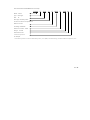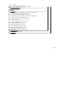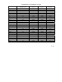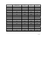
1
REV. 3.3
CS Family CS3□□A,C,D MFC/MFM
User’s
Manual
2015.4
Contents
SECTION 1 INTRODUCTION
1.1 Declaration ...................................................
1.2 Attention.......................................................
1.3 The notice of safety ......................................
1.4 General .........................................................
1.5 Specification .................................................
1.6 Calibration features .....................................
SECTION 2 INSTALLATION
2.1 General .........................................................
2.2 Unpacking .....................................................
2.3 Mechanical Installation ...............................
2.3.1 General........................................................
2.3.2 Installation ..................................................
2.3.2.1 1/4VCR Installation .................................
2.3.2.2 Two-ferrule Connector Installation ..........
2.3.2.3 IGS Connector Installation.......................
2.4 Electrical Installation...................................
2.4.1 General........................................................
2.4.2 Connections ................................................
2.4.3 Table of Cable .............................................
2.5 Checking Before Operation.........................
SECTION3
3.4 Soft-Start .........................................................
1
2
2
3
5
8
3.2 Control Mode ...............................................
3.3 Zero ...............................................................
3.6 Valve Command Mode ...................................
3.7 Valve Type .......................................................
3.8 Multi-Gas and Multi-Flow .............................
3.9 Total Flow Accumulator .................................
3.10 Alarm .............................................................
3.11 LED ................................................................
9
9
10
10
19
19
20
21
21
21
22
23
25
SECTION 4
26
26
26
27
27
27
27
28
28
28
29
MAINTENANCE
4.1 General ............................................................
4.2 Caution ............................................................
4.2.1 Medium Forbidden .....................................
4.2.2 Seal of Valves .............................................
30
30
30
30
SECTION 5 TROUBLESHOOTING
5.1 Initial check .....................................................
31
5.2 Troubleshooting ..............................................
31
SECTION 6 WARRANTY AND SERVICES
6.1 Guarantee of Sevenstar ..................................
6.2 Product Warranty…………………………...
6.3 Services ............................................................
6.4 Disclaimer ........................................................
APPENDIX I .........................................................
FUNCTIONS
3.1 General...........................................................
3.5 Delay ................................................................
APPENDIXⅡ .......................................................
APPENDIXⅢ .......................................................
32
32
34
34
35
38
41
MFC/MFM
User’s
Manual
SECTION 1 NTRODUCTION
1.1 Declaration
The copy right of The user’s manual of mass flow controller and mass flow meter is
subjected to Beijing Sevenstar Electronics Co., Ltd (following abbr. Sevenstar), which is
not allowed to duplicate, store and distribute any part of this manual in mean of electric,
mechanical, photocopy, recording or other way without permission of Sevenstar. This
manual is not assured that there is no mistake and missing in which have been corrected
strictly, and the publisher is under no obligation to the mistake or missing, meanwhile the
publisher is not in charge of any loss that this manual leads to.
Beijing Sevenstar Electronics Co. , Ltd
1 / 42
1.2 Attention
Dear customer, thanks for using CS mass flow controller and mass flow meter. This
manual describes in detail important issues about correct and safe operations of the
product.
User of the product should read and comprehend this manual and pay attention to the
text with labels
and notices.
Sevenstar assumes no liability for the customer’s failure to comply with this manual.
This manual is necessary for your installation and maintenance, please keep it carefully.
1.3 The notice of safety
Please pay attention to the below notices when reading this manual. We are not responsible
for any result without abiding by the below notices.
a) Do not replace any components or disassemble instrument.
Do not replace any components, or disassemble the instrument without any authorized
and make sure that the label or/and seal of product is not removed when returning for
reworking, recalibration and maintenance.
b) Please contact professional for technical service.
Do not replace any components. Any technical support is provided by professional who
must be authorized by Sevenstar.
c) Please pay more attention to use dangerous gas.
Instrument should be purged completely and keep safety if dangerous gas is used.
Meanwhile make sure that moist gas must not react with material of seal and
instrument.
d) Please pay attention to purging instrument.
The whole system should be purged by dry gas after and before the instrument is
installed.
e) Please abide by proper steps of purging.
Product should be purged and handled with gloves.
f) Do not use the instrument in explosive environment.
Do not use the instrument in explosive environment, unless the safety certificate is
2 / 42
available.
g) Please use proper fittings and keep the rules.
All fittings of instrument must be matched according to the listing in manual. Please
read manual carefully before screwing tightly.
h) Please do leakage check.
Please check carefully all of vacuum parts and make sure that there is not leakage in
the system.
i) Please make sure that instrument is working under safe pressure.
Please make sure that the pressure of inlet gas is less than maximum working pressure
(referring to maximum working pressure in manual).
j) Please keep the whole system away from pollution.
When system running, do not use polluting gas, such as particle of dust, dirt, fibre,
glass or scrap iron.
k) Please do warm-up instrument before working.
Please do warm-up instrument, especially in using dangerous gas. Please close valve
completely to make sure that there is not error flow.
1.4 General
Mass flow controller (MFC) accurately measures and controls mass flow rates, which
is widely applied in the fields as: semiconductor and IC fabrication, special materials
science, chemical industry, petrolic industry, pharmaceutical industry, environmental
protecting and vacuum system researching, etc.. The typical applications include:
microelectronic process equipment such as diffusion, oxidation, epitaxy, CVD, plasma
etching, sputtering, ion implantation, vacuum deposition equipment, optical fiber melting,
micro-reaction equipment, mixing & matching gas system, capillary flow control system,
gas chromatograph and other analytical instruments.
The CS3□□ MFC/MFM is the latest generation digital MFC of Sevenstar for
3 / 42
semiconductor applications and industrial applications where high accuracy and flexibility
in interfacing are required.
The CS3□□ MFC/MFM incorporates pressure compensation, standard IGS fitting, a
dual interface, voltage as well as RS-485 and DeviceNet digital interfaces. It is possible to
operate the instrument completely digitally or it can be operated in analog mode with
digital monitoring. CS3□□ MFC/MFM supports wide range of power supply(available
for ±8 ~ ±16 VDC or +14 ~ +28 VDC).
In addition, auto-alarm, multi-gas and multi-range are available through the digital
interface. Customer Development of control software information, sample software and
example source code are available in the product accessories.
CS3□□ default configuration:
MAC Address: 32;
RS 485 baud rate: 19200;
Control Mode: 0~5V analog control
For more information, Please refer to Digital MFC Communication User Manual in
the disc.
4 / 42
1.5 Specification
CS3□□C
Type
Valve Type
CS310C
CS320C
Normally Closed or Normally Open
N/A
( 0~1,2,3,5,10,20,30)SLM
±1.0% S.P. (≥35% F.S.)
Accuracy
(±0.80% S.P. (≥30% F.S.) optional)
±0.35% F.S. (<35% F.S.)
Linearity
(±0.24% F.S. (<30% F.S.) optional)
±0.5% F.S.
Repeatability
Response
Time
±0.2% F.S.
≤ 0.8 sec (standard)
0.05~0.35MPa (Flow≤10slm)
0.05~0.35MPa (Flow≤10slm)
<0.02 Mpa
0.15~0.35MPa (Flow>10slm)
Temperature
0.15~0.35MPa (Flow>10slm)
3.5MPa (435pisg)
1×10-11 Pa.m3 / sec He
Metal
(0~50)℃
Temperature
Digital: RS485 or DeviceNet
TM
Digital:RS485 or DeviceNetTM
N/A
Analog:(0~5)VDC
Analog:(0~5)VDC
N/A
Digital: RS485 or DeviceNetTM
Output
Signal
Analog:(0~5)VDC
Zero Drift
Power
Supply
Surface
Chemistry
Surface
Finish
<0.6%F.S. per year without autozero
±8 ~ ±16 VDC (bipolar) or +14 ~ +28 VDC (unipolar)
Cr/Fe ratio >2.0; CrO thickness >20 Angstroms
Ra 5 μ inch
Fittings
VCR1/4” M;
1.5″B
1.125″C Type
1.5″C
1.125″W Type
Electronic
Connector
Weight
<0.02MPa
Zero:≤±0.02% F.S./℃; Span:≤±0.05% F.S./℃
Coefficient
Max
Pressure
Leak
integrity
Seal
Materials
Operation
Input Signal
N/A
( 0~1,2,3,5,10,20,30,50,100,200,300,500)SCCM
Full scale
range (N2)
Differential
Pressure
Normally Closed or Normally Open
1.5″W
9 pin male sub-D ,15 pin male sub-D ,DeviceNet
1kg
0.8kg
TM
male,
1.2kg
1kg
5 / 42
CS3□□D
Type
Valve Type
CS310D
CS320D
Normally Closed or Normally Open
N/A
Normally Closed or Normally Open
( 0~1,2,3,5,10,20,30)SLM
±1.0% S.P. (≥35% F.S.)
Accuracy
(±0.80% S.P. (≥30% F.S.) optional)
±0.35% F.S. (<35% F.S.)
(±0.24% F.S. (<30% F.S.) optional)
Linearity
±0.5% F.S.
Repeatability
Response
Time
±0.2% F.S.
Differential
Pressure
≤ 0.8 sec (standard)
0.05~0.35MPa (Flow≤10slm)
0.05~0.35MPa (Flow≤10slm)
<0.02 Mpa
0.15~0.35MPa (Flow>10slm)
Temperature
0.15~0.35MPa (Flow>10slm)
3.5MPa (435pisg)
1×10-11 Pa.m3 / sec He
Metal
(0~50)℃
Temperature
Digital: RS485 or DeviceNet
TM
Digital:RS485 or DeviceNetTM
N/A
Analog:(0~5)VDC
Analog:(0~5)VDC
Digital: RS485 or DeviceNet
Output
Signal
N/A
TM
Analog:(0~5)VDC
Zero Drift
Power
Supply
Surface
Finish
<0.6%F.S. per year without autozero
±8 ~ ±16 VDC (bipolar) or +14 ~ +28 VDC (unipolar)
Ra 25 μ inch
Fittings
VCR 1/4” M;
1.5″B
1.125″C Type
1.5″C
1.125″W Type
Electronic
Connector
Weight
<0.02MPa
Zero:≤±0.02% F.S./℃; Span:≤±0.05% F.S./℃
Coefficient
Max
Pressure
Leak
integrity
Seal
Materials
Operation
Input Signal
N/A
( 0~1,2,3,5,10,20,30,50,100,200,300,500)SCCM
Full scale
range (N2)
1.5″W
9 pin male sub-D ,15 pin male sub-D ,DeviceNet
1kg
0.8kg
TM
male,
1.2kg
1kg
6 / 42
CS3□□A
Type
Valve Type
CS310A
CS320A
Normally Closed or Normally Open
N/A
Normally Closed or Normally Open
( 0~1,2,3,5,10,20,30,50)SLM
±1.0% S.P. (≥35% F.S.)
Accuracy
±0.35% F.S. (<35% F.S.)
Linearity
±0.5% F.S.
Repeatability
Response
Time
±0.2% F.S.
Differential
Pressure
≤ 1 sec (standard)
0.05~0.35MPa (FLOW≤10SLM)
0.15~0.35MPa (10SLM<FLOW≤30SLM)
0.25~0.35MPa (30SLM<FLOW≤50SLM)
<0.02 Mpa
Coefficient
Max
Pressure
Leak
integrity
Seal
Materials
Operation
1×10⁻¹⁰ Pa.m3 / sec He
Viton
(0~50)℃
Digital: RS485 or DeviceNetTM
Analog:(0~5)VDC
Digital:RS485 or DeviceNetTM
N/A
Analog:(0~5)VDC
Digital: RS485 or DeviceNet
Output
Signal
N/A
TM
Analog:(0~5)VDC
Zero Drift
Power
Supply
Surface
Finish
<0.6%F.S. per year without autozero
±8 ~ ±16 VDC (bipolar) or +14 ~ +28 VDC (unipolar)
Ra 25 μ inch
VCR1/4” M;
VCO1/4” M;
Compression FittingΦ10;
Compression Fitting 3/8”;
Compression Fitting1/8”;
Ф6(inner)×1hose;
Electronic
Connector
Weight
<0.02MPa
3.5MPa (435pisg)
Temperature
Fittings
0.05~0.35MPa (FLOW≤10SLM)
0.15~0.35MPa (10SLM<FLOW≤30SLM)
0.25~0.35MPa (30SLM<FLOW≤50SLM)
Zero:≤±0.05% F.S./℃
Span:≤±0.1% F.S./℃ FLOW≤30SLM
Span:≤±0.2% F.S./℃ 30SLM<FLOW
Temperature
Input Signal
N/A
( 0~5,10,20,30,50,100,200,300,500)SCCM
Full scale
range (N2)
Compression FittingΦ6;
Compression Fitting1/4”;
Compression FittingΦ3;
ф5(inner)×1.5hose;
ф4(inner)×1hose;
9 pin male sub-D ,15 pin male sub-D ,DeviceNetTM male,
1kg
0.8kg
1.2kg
1kg
7 / 42
Notes
:
MFC/MFM is calibrated by N2 as a standard gas.
Units:
SCCM (Standard Cubic Centimeter/Min);
SLM
(Standard Liter/Min)
Standard Situation:
Tem — 273.15K ( 0 ºC );
Air Pressure — 101325 Pa (760mm Hg)
For Sevenstar MFC/MFM, the unit of SCCM is identical to “mL/min, 0 ºC ,1atm”, and the unit of SLM
is identical to “L/min, 0 ºC ,1atm”.
F.S. :
Full Scale
1.6 Calibration Features
Normally, the CS3□□
MFC/MFM is calibrated according to customer’s
requirements (the requirements should be accorded with the specification). Without
customer’s information, the MFC is calibrated under standard conditions.
1.6.1 Standard conditions
Without special conditions specified by the customer, the MFC is calibrated under the
following standard conditions:
Pressure Outlet: Atmospheric.
Normally gas mass flow rate is transferred to gas volume flow rate at standard state.
Mass flow rate unit:
SCCM——standard cubic centimeter per minute.
SLM——standard liter per minute.
Standard state:Temperature —— 0ºC (273.15K)
Pressure —— 101325Pa (760mmHg)
At standard state, the gas density will be constant. The multiplication of density and
volume flow rate is equal to the mass flow rate. Therefore at the standard state, the volume
8 / 42
flow rate will represent mass flow rate.
1.6.2 Manufacturing Environment
The CS3□□ MFC/MFM is assembled in a class 100 clean room, calibrated,
packaged and controlled in class 1000 environment. The calibration temperature is
23±2℃.
1.6.3 Precision Adjustment
CS3□□MFC/MFM is burned for 24 hours after manufacturing. The accuracy, the
dynamic response, the stability to pressure variations are double checked. Only qualified
product could be sent to customers.
SECTION 2
INSTALLATION
2.1 General
WARNING: Toxic, corrosive or explosive gases must be handled with extreme care.
After installing the MFC, the system should be thoroughly checked to ensure it is leak-free.
Purge the MFC with a dry inert gas for one hour before using corrosive gases.
IMPORTANT: When installing the MFC, ensure that the arrow on the back of the unit
in the same direction as the gas flow.
2.2 Unpacking
The CS3□□ MFC/MFM is assembled,calibrated and packaged under clean room
conditions. These products are packaged with two separately sealed plastic bags. The
outside is common plastic bag and the inside is clean vacuum bag. The outside bag should
be removed in the entrance to the clean room. In order to minimize the contamination, the
9 / 42
second clean bag should be removed in the clean room when MFC installed in the system.
2.3 Mechanical Installation
2.3.1 General
Most applications will require a positive shutoff valve in line with the MFC.
Pressurized gas trapped between the two devices can cause purge effects, and consideration
must be given to the sitting of the shutoff valve (upstream or downstream) in relation to the
process sequencing. It is recommended to install an in-line filter upstream to the controller
in order to prevent MFC from contamination.
CS3□□ should be mounted in the position accord with the requirement in the
purchase order. The gas should be clean and dry. The mounting should be free from shock
or vibration. The dimensions of the product are shown in figure2-1, figure2-2, figure2-3,
figure2-4 and figure2-5. Do not remove the protective end caps of the fittings until
installation.
10 / 42
〃
Figure 2-1 CS310C,D 1.125 IGS
11 / 42
〃
Figure 2-2 CS310C,D 1.125 DeviceNet
12 / 42
〃
Figure 2-3 CS310C,D 1.125
1/4VCR Fitting
13 / 42
〃
Figure 2-4 CS310A 1.125 Product dimensions with different fittings
14 / 42
Fitting
Length
Compression Fittingφ6;
Compression Fitting1/4;
Compression Fitting1/8;
Compression Fittingφ3
VCR1/4〞 M
Compression Fittingφ10
Compression Fitting3/8
Ф4(inner)×1hose
VCO1/4〞 M
Ф6(inner)×1hose
Ф5(inner)×1.5hose
L(mm)
112.8
116.6
117.6
124
Table 2-1 The length of the product with different fittings
15 / 42
〃
Figure 2-5 CS320A 1.5 Product dimensions with different fittings
16 / 42
〃
Figure 2-6 CS320C,D 1.5 IGS
17 / 42
〃
Figure 2-7 CS320C,D 1.5 DeviceNet
18 / 42
Attention
:
The height (which is shown in figure 2-1, figure 2-3, figure 2-4,figure 2-5 and figure 2-6) of 127.20mm
are height without electric connectors of cable. It should be added around 50mm more after adding the
electric connector.
2.3.2 Installation
Place MFC/MFM according to the flow direction.
2.3.2.1 1/4VCR Connection
Refer to figure 2-8 and figure 2-9. Check the gland to gland space, including the
gaskets. Remove the plastic gland caps. When using loose VCR original style gaskets,
inserting the gasket into the female nut. For VCR retainer gaskets, snap the gasket onto the
male coupling. Tighten the nuts finger tight. Scribe both nut and body in order to mark the
position of the nut. While holding the body with a wrench, tighten the nut: 1/8 turn past
finger tight for 316L stainless steel and nickel gaskets.
Figure 2-8 VCR original style gasket
Figure 2-9 VCR retainer gasket
19 / 42
2.3.2.2 Two-ferrule (Compression Fitting) Connection
Refer to figure 2-10. Check the gland to gland space. Remove the gland protector caps.
Insert the tubing to the shoulder inside the fitting, and check that the ferrules are positioned
as shown in figure2-10. Tighten the nuts finger tight. Use two spanners, one spanner
locking the fitting stable, wrench another one to tighten in 1.25 turns to prove it’s not
blow-by after installing the front ferrule, back ferrule and nut.
Gland
Nut
Back ferrule
Front ferrule
Fitting
Figure 2-10 Compression Fitting Connector Installation
Attention
:
When installing the fitting, you should manually use spanner to wrench it tighten by 1/2 turn pulling up,
(imported Compression Fitting should use spanner to be tighten in 1,25 turns) to prove its not blow-by
after your installing the front ferrule 、back ferrule and nut. Please note you should use two spanners to
operating, one spanner for locking the fitting stable and another one for revolving the nut. Especially when
you dismantle the tube, you should operate by the two spanners otherwise fitting will become flexible
which will affect its airproof function.
20 / 42
2.3.2.3 IGS fitting installation
Refer to figure 2-11. To select the correct seal according to type of IGS fitting (W
Type or C Type), which is put in IGS fitting, and fix it on gas line of MFC by screw with
5N.mm.
Figure 2-11 IGS fitting Installation
2.4 Electrical Installation
2.4.1 General
With simple switching power supply, CS3□□ MFC/MFM is available for ±8 to ±16
VDC (dual-ending) or +14 to +28 VDC (single-ending). Customer can choose as need.
Customer can choose 9 pin male Sub-D or 15 pin male sub-D connector. 9 pin male
Sub-D connector is the SEMI Standard compatible, only 0-5V analog signal control and
21 / 42
output available.
CS3□□ MFC/MFM can communicate with PC via RS485 or DeviceNet.
2.4.2 Connections
9 pin male Sub-D connector, 15 pin male sub-D connector, RS485 connector,
DeviceNet connector and RS232-RS485 connector are shown in figure2-12, figure2-13,
figure2-14, figure 2-15 and figure 2-16.
Attention
:
Although sharing with the same appearance of CS3□□ MFC, the 0~5V Setpoint Input, and the valve
Over-ride of CS3□□ MFM are not available. That means pin1 and pin6 of D-sub 9(figure 2-12) and pin1,
pin7, pin8 and pin12 of D-sub 15(figure 2-13) in MFM are not available.
Figure 2-12 9 pin male D-sub connector
Figure 2-14 RS485
Figure 2-13 15 pin male D-sub connector
Figure 2-15 DeviceNet
Figure 2-16 RS232-RS485
22 / 42
2.4.3 Table of Cable and its Illustration of Connection
D082B/3B/4B
2E/3E/4E
D08- 1/2/4 2F/3F/4F
D08-1F/1FM/1FS/8C/8CM/1G/1GM
Input
±15V
Input
+24V
To Serial
Port of
Computer
To USB
of
Computer
MFC
(DB15 Pin)
QCX-19/
QCX-P19
QCX-48
QCX-17/QCX-P17
QCX-46
QCX-41
QCX-43
QCX-34
QCX-50
MFC
(DB9 pin)
QCX-20/
QCX-P20
QCX-49
QCX-18/QCX-P18
QCX-47
QCX-42
QCX-34
QCX-50
Table 2-2
Table of Cable
Figure 2-17 Illustration of Connecting Power D08-1D/1F
23 / 42
Figure 2-18 Illustration of Connecting Power for ±15V
Figure 2-19 Illustration of Connecting Power for +24V
24 / 42
Figure 2-20 Illustration of Connecting CS Products
Sevenstar manufactures all standard cables, RS485 adaptor, customized cables and
some accessories. For more details, contact Sevenstar or its local agent.
2.5 Checking Before Operation
Before operating the MFC the following checks should be completed:
25 / 42
2.5.1 Check that tubing is leak free.
2.5.2 Check the process sequence and proper function of all other gas components
involved.
2.5.3 Check the voltage of command signals and power supply to the MFC/MFM.
2.5.4 Check that the appropriate type of gas is being supplied at the rated pressure.
2.5.5 Warm up MFC/MFM for 20 minutes, and then check the zero level output.
2.5.6 Use dry inert gas for test runs.
2.5.7 Before using the MFC for extremely corrosive gases, purge MFC with a dry inert gas
for one hour.
SECTION3 FUNCTIONS
3.1 General
Based on new sensor driver technology, zero balance technology and VCP technology,
CS3□□ MFC/MFM presents high performance and reliability. And more digital functions
are developed in CS3□□ products.
3.2 Control Mode
CS3□□ MFC/MFM is available for digital and 0-5V analog control mode. When
customer chooses one of the two control modes, another will be blocked. The analog
output and digital output are sent out all the time.
Please refer to ”Digital MFC Communication User Manual” for more details.
3.3 Zero
The Zero function can be commanded through the digital interface or zero-button.
26 / 42
Before zero MFC, please make sure that no gas flow through MFC. Then zero MFC
through the digital interface or zero-button. The zero-button must be pressed continuously
for 0.5 seconds in order to start zero process. The green LED will blink during the zero
process. After zero finished, the green LED will be on constantly.
3.4 Soft-Start
The CS3□□ MFC/MFM supports soft-start function. Soft-start allows customer
change the setting of MFC with definite rate. Please refer to “Digital MFC Communication
User Manual” for more details.
3.5 Delay
Delay is used to postpone the start of flow from zero to Setpoint. It is programmed in
millisecond but the MFC internally rounds up any value to 100ms. For example, when the
delay value is 200, MFC will delay 200ms then receiving the operate command. When the
Setpoint is less than the minimum control rate, the valve will shut off, and when larger than
the minimum control rate, MFC will start after the set delay time.
Special default: Values from 1 to 49 ms will be programmed as 100ms.
3.6 Valve Command Mode
CS3□□ MFC/MFM is available for valve-close or valve-open by input digital signal
or analog voltage directly. The Valve Command Mode is used to select one of three ways
to interpret the analog signal of Valve Command. Please refer to ”Digital MFC
Communication User Manual” for more details.
3.7 Valve Type
CS3□□ MFC/MFM has two types of valve: Normally open (NO) or Normally closed
27 / 42
(NC). When MFC does not have power supply, the “NO” type valve will open; the “NC”
type valve will shut down. Please mention the valve type when you order the MFC.
3.8 Multi-Gas and Multi-Range
The multi-gas and multi-range technology has been developed in the CS3□□ series
MFC/MFM. Customer can change gas convert factor, full scale of MFC via digital
interface. Full scale of CS3□□ MFC/MFM can be re-ranged from 30% to 110%F.S. For
example, an MFC with 100SCCM full scale, the new full scale can be re-ranged between
from 30SCCM to 110SCCM.
CS3□□ MFC/MFM support customer offset by the target null value. The target null
value is a customer-programmed constant used to offset the flow output independently of
all other sensor offset constants, including the zero process. For example, set Target Null
Value: -20%F.S,then when no flow through MFC/MFM,the reading will be -20%F.S,
With gas flow 20%F.S through MFC/MFM,the reading will be 0%F.S。Offset range is
from -100%F.S to100%F.S。
Please refer to “Digital MFC Communication User Manual” for more details.
3.9 Total Flow Accumulator
The Total Flow accumulator will record the amount of gas (in SCC) that has been
delivered by CS3□□ MFC/MFM. The amount of purge will not be accumulated in the
total flow amount. For example, the total reading is 3000, means the amount of gas
delivered by MFC is 3000SCC
Please refer to “Digital MFC Communication User Manual” for more details.
3.10 Alarm
The CS3□□ MFC/MFM will monitor and store certain abnormal conditions as
28 / 42
described below. These conditions can be read and reset from the RS485 interface.
Provisions will be made for masking (disabling) the alarms or warnings on an individual
basis.
Warning and Alarms:
Sensor Zero Drift
EEPROM Failure
Valve Coil Failure
Temperature Alarm
After power up the LED on the top of the CS3□□ MFC/MFM is turned GREEN. A
warning condition will be announced by a blinking RED, Whenever an alarm condition is
detected it will be set continuously to RED.
Please refer to “Digital MFC Communication User Manual” for more details.
3.11 LED
There is a green-red LED located on the top of the MFC. The constant green LED
indicates the power on. Green blinking indicates that the MFC is zeroing. A blinking red
LED indicates warning condition. Constant red indicates error condition.
In DeviceNet connection, there will be 2 LED on the top of CS3□□, refer to
CS200MFC (CS220) _DnetSpecification_V1.01 for more details.
Attention
:
When the Valve of MFC is posited on “PURGE”, it can be functioned as a MFM. In that case, the
maximum flow testing voltage could reach beyond +10V, please be careful, while flow is beyond F.S.
+5V(Full Scale), the real flow will have no linearity corresponding with flow testing voltage. While it’s
purging, flow display will be inaccurate, even showing “reduce” while the real flow is enhanced, please be
sure it’ll be no damaged to device itself.
29 / 42
SECTION 4
MAINTENANCE
4.1 General
No routine maintenance is required to be performed on the MFM or MFC, Other than
occasional cleaning and re-calibration:
It can be used about 3 or 4 years with an ultra-clean and non corrosive gas.
It can be used about 1 or 2 years with a low purity gas or a corrosive gas.
For any other problems, contact Sevenstar.
4.2 Caution
4.2.1 Medium Forbidden
The gas should be purified without dust,liquid and oil stain. If necessary, the filter
should be added to gas system for purification. If the outlet of MFC is connected to liquid
sources, a One-way valve should be added to avoid the liquid back to destroy MFC.
Attention
:
For the cases that the MFC/MFM used with toxic, pyrophoric, flammable or corrosive gas, you should ensure
that the fixing and fitting are airtight. It becomes necessary to remove the controller from the system, purge the
controller thoroughly with a dry inert gas such as nitrogen, before disconnecting the gas connections. Failure to
purge the controller could cause a fire or explosion resulting in death.
4.2.2 Seal of Valves
The Solenoid Valve of MFC is only for adjustment, can not be used for shut-off.
Generally, shut-off valves should be added in upstream and downstream of MFC for
protection. Normally leakage of MFC valve is not more than 1% F.S.
30 / 42
SECTION 5
TROUBLESHOOTING
5.1 Initial Check
5.1.1 Check the gas supply pressure and check the flow-path to the MFC/MFM has been
opened.
5.1.2 Ensure that the power supply and command signals are correctly transmitted to the
D-connector pins and RS485.
5.1.3 Check that the cable and connector are ready.
5.2 Troubleshooting
Use the following table to locate the fault.
SYMPTOMS
1
Output reading,
without gas flow, is
not zero
Possible cause
Gas flow is actually
present
Check closure of shutoff valve
Zero drift
Zero MFC
other
*Contact Sevenstar
Gas connection incorrect
Pressure incorrect
Check gas connection
Check pressure condition
Wrong control mode
2
MFC out of control
Power failure
Setpoint incorrect
Action
Change the control mode by the
software
Check Power and pin position
Check setpoint signal
Contamination
Defective sensor
*Contact Sevenstar
PCB problems
*Contact Sevenstar
*Contact Sevenstar
31 / 42
3
Attention
MFC dose not
communicate with
PC
Defective Mechanics
*Contact Sevenstar
Power failure
Cable problems
Address conflict
Baud rate error
PCB problems
Check Power and pin position
Check cable and connector
Check address of MFC
Check baud rate of MFC
*Contact Sevenstar
:
* Mark indicates that repair and adjustment must be dealt under specialist advices。For any other problems,
contact Sevenstar.
SECTION 6 WARRANTY AND SERVICES
6.1 Guarantee of Sevenstar
Sevenstar and its authorized distributors assure that there are not flaws in the materials
and quality of products within 12 months from the date of purchase.
The compensation for customer is only limited to invalid part for substitution,
installation and processing flaw.
It is guaranteed that all parts chosen by customers are suitable to relative
manufacturer.
Other relative statements, guarantee and obligation of status and usage of product,
whether direct or indirect, are definite to be excluded. In any circumstance, Sevenstar is
not charged of any obligation of direct or indirect loss for customers or others.
6.2 Product Warranty
6.2.1 Sevenstar products are guaranteed against defects in materials and workmanship if
used in accordance with specifications and not subject to physical damage, contamination,
alteration or retrofit. Warranty periods: One year
6.2.2 Buyers undertake to check and inspect the goods and to notify Sevenstar of shipment
incidents by fax, phone or e-mail as soon as possible after accepting the goods.
6.2.3 During the warranty period, products must only be repaired by authorized Sevenstar
32 / 42
service centers; otherwise, the Sevenstar product warranty will be invalidated.
6.2.4 Repairs will be free of charge during the one-year warranty period. If MFC is out of
warranty, Sevenstar will notify the owner of replacement or repair costs before proceeding.
Factory service and repairs are guaranteed 90 days. The warranty excludes consumable
materials and wear parts (in teflon, viton, etc.).
6.2.5 No MFC will be accepted for repair or warranty without a decontamination and purge
certificate.
6.2.6 Each MFC is individually checked (visual inspection of fittings, helium leak test and
flow calibration). Sevenstar shall not be responsible for any damage caused by gas leakage
or the use of a dangerous gas. Users are responsible for following the safety rules
applicable to each gas they use. Improper use of a Sevenstar MFC will void the warranty,
and MFC that have been damaged as a result of improper use will not be replaced by
Sevenstar.
6.2.7 Specific warranty requirements are as follows :
a,Gas must be clean and particle-free, which means a filter must be fitted in the gas
line upstream of the MFC.
b,Gas must comply with the following pressure specifications:
1. Gas pressure must never exceed 3MPa.
2. Differential pressure must be more than 0.05MPa for full-scale flow through the
MFC valve unless another value is specified in the user’s manual.
3. Differential pressure must be less than 0.35MPa for the MFC valve to regulate
without gas-flow oscillation unless another value is specified in the user’s manual.
4. Pressure at the mass-flow inlet must be regulated by an accurate pressure regulator
to prevent gas-flow oscillation.
c,Electrical connection requirements are as follows:
33 / 42
The system must be wired carefully: non-observance of the pin-out may irreversibly
damage the electronic board inside the MFC, in which case the warranty will be
invalidated.
d,Gas connections: The fittings must be handled carefully. Sevenstar guarantees that
all fittings have been individually inspected and are scratch-free.
e,Fitting procedure: The fitting procedure set out in the manual must be followed
meticulously. Specifically, the purge procedure is very important if corrosive gases or toxic
gases are used.
f,The mass-flow must not be dismounted: The MFC warranty will be invalidated if
the seal between the MFC block and cover is torn.
6.3 Services
Sevenstar can provide services like start-up service, software development, gas
system design, training, etc.
Please visit www.mfcsevenstar.cn for more information and find your nearest service
and calibration centre.
6.4 Disclaimer
Beijing Sevenstar Electronics Co., Ltd is not responsible for loss as following situation:
1. Nature disaster and calamity;
2. Unsuitable operation and unreasonable usage;
3. Operating and storing in inappropriate or execrable circumstance;
4. Usage of instrument beyond user’s manual;
5. Unauthorized change or replacement of product.
For example:
It is whether that gas path is not cleared before using corrodible gas or MFC is
contaminated or blocked by particle such as dust.
34 / 42
Appendix I CS310 Selection Guide
CS310-[t]
[g,g,g]
[v]
[w] [r,r,r,r]
[a]
[f,f]
[s]
[d]
[t] –Type
- [A] Elastomer type, 1.125” Ra 25μinch
- [C] Metal type, 1.125” Ra 5μinch
- [D] Metal type, 1.125” Ra 25μinch
[g,g,g] –Gas
Standard: SEMI52-0302 For example
-[ 013 ] N2
-[ 000 ] Mixture Gases (please consult [d] for details)
[v] – Type of Valve
- [ O ] Normally open
- [ C ] Normally closed
- [ N ] No Valve
[w] –Function of Pressure Compensation
- [ P ] With the function of pressure compensation
(available to type C, D only, and unavailable to MFM)
- [W ] Without the function of pressure compensation
[r,r,r,r] –Full Scale
- [ 001C]
1SCCM
Minimum
- [ 001C]
1SCCM
(available to type C, D only)
- [ 002C]
2SCCM
(available to type C, D only)
- [ 003C]
3SCCM
(available to type C, D only)
- [ 005C]
5SCCM
- [ 010C]
10SCCM
- [ 020C]
20SCCM
- [ 030C]
30SCCM
- [ 050C]
50SCCM
- [ 100C]
100SCCM
- [ 200C]
200SCCM
- [ 300C]
300SCCM
- [ 500C]
500SCCM
- [ 001L]
1SLM
- [ 002L]
2SLM
- [ 003L]
3SLM
- [ 005L]
5SLM
- [ 010L]
10SLM
- [ 020L]
20SLM
- [ 030L]
30SLM
35 / 42
- [ 050L]
- [ 000C]
50SLM (available to type A only)
customized Full scale, please consult [d] for details
[a] –Electronic connector
- [ R ] DB 9 pin
- [ D ] DB15 pin
- [ X ] DeviceNet connector
[f,f] –Fittings
-[AA]
Compression Fittingφ3mm (available to type A only,and FLOW≤5SLM)
-[GG]
Compression Fittingφ6mm (available to type A only)
-[JJ ]
Compression Fittingφ10mm (available to type A only)
-[BB]
Compression Fitting 1/8" (available to type A only,and FLOW≤5SLM)
-[CC ] Compression Fitting 1/4" ( available to type A only)
-[HH ]
Compression Fitting 3/8"( available to type A only)
-[MM]
VCR 1/4" male Fitting
-[UU]
VCO 1/4" male Fitting (available to type A only)
-[SC ]
IGS C seal (available to type C, D only)
-[SW] IGS w seal (available to type C, D only)
-[RR]
φ6(inner)x1hose (available to type A only)
-[VV]
φ5(inner)x1.5hose (available to type A only)
-[TT] φ4(inner)x1hose (available to type A only)
-[XX ] customized fittings please consult [d] for details
[s] –Seal Materials
-[ V ] Viton(available to type A, only)
-[ M ] Metal (available to type C, D only)
[d] –Description
36 / 42
Take CS310C013CP500CDMMMS as the example
CS310
C
013
C
P
500C
D
MM
M
S
Model:CS310
Type:
Metal type
Gas:
N2
Valve Type: Normally closed
Function of Pressure Compenasation:
With the Function
Full Range: 500SCCM
Electronic connector:DB15
Fittings:1/4”VCR
Seal material: 316L
Customized requiremen:
For example
Customized requirement: In Chinese. Differential pressure, (0.3-0.5)MPa, customized fittings, customized calibration temperature, 40℃
37 / 42
Appendix II CS320 Selection Guide
CS320-[t]
[g,g,g]
[v]
[w] [r,r,r,r]
[a]
[f,f]
[s]
[d]
[t] –Type
- [A] Elastomer type, 1.5” Ra 25μinch
- [C] Metal type, 1.5” Ra 5μinch
- [D] Metal type, 1.5” Ra 25μinch
[g,g,g] –Gas
Standard: SEMI52-0302 For example
-[ 013 ] N2
-[ 000 ] Mixture Gases (please consult [d] for details)
[v] – Type of Valve
- [ O ] Normally open
- [ C ] Normally closed
- [ N ] No Valve
[w] –Function of Pressure Compensation
- [ P ] With the function of pressure compensation
(available to type C, D only, and unavailable to MFM)
- [W ] Without the function of pressure compensation
[r,r,r,r] –Full Scale
- [ 001C]
1SCCM
Minimum
- [ 001C]
1SCCM
(available to type C, D only)
- [ 002C]
2SCCM
(available to type C, D only)
- [ 003C]
3SCCM
(available to type C, D only)
- [ 005C]
5SCCM
- [ 010C]
10SCCM
- [ 020C]
20SCCM
- [ 030C]
30SCCM
- [ 050C]
50SCCM
- [ 100C]
100SCCM
- [ 200C]
200SCCM
- [ 300C]
300SCCM
- [ 500C]
500SCCM
- [ 001L]
1SLM
- [ 002L]
2SLM
- [ 003L]
3SLM
- [ 005L]
5SLM
- [ 010L]
10SLM
- [ 020L]
20SLM
38 / 42
- [ 030L]
- [ 050L]
- [ 000C]
30SLM
50SLM (available to type A only)
customized Full scale, please consult [d] for details
[a] –Electronic connector
- [ R ] DB 9 pin
- [ D ] DB15 pin
- [ X ] DeviceNet connector
[f,f] –Fittings
-[AA]
Compression Fittingφ3mm (available to type A only,and FLOW≤5SLM)
-[GG]
Compression Fittingφ6mm (available to type A only)
-[JJ ]
Compression Fittingφ10mm (available to type A only)
-[BB]
Compression Fitting 1/8" (available to type A only,and FLOW≤5SLM)
-[CC ] Compression Fitting 1/4" ( available to type A only)
-[HH ]
Compression Fitting 3/8"( available to type A only)
-[MM]
VCR 1/4" male Fitting
-[UU]
VCO 1/4" male Fitting (available to type A only)
-[SB ]
IGS B seal (available to type C, D only)
-[SC ]
IGS C seal (available to type C, D only)
-[SW] IGS w seal (available to type C, D only)
-[RR]
φ6(inner)x1hose (available to type A only)
-[VV]
φ5(inner)x1.5hose (available to type A only)
-[TT] φ4(inner)x1hose (available to type A only)
-[XX ] customized fittings please consult [d] for details
[s] –Seal Materials
-[ V ] Viton(available to type A, only)
-[ M ] Metal (available to type C, D only)
[d] –Description
39 / 42
Take CS320C013CP500CDMMMS as the example
CS320
C
013
C
P
500C
D
MM
M
S
Model:CS320
Type:
Metal type
Gas:
N2
Valve Type: Normally closed
Function of Pressure Compenasation:
With the Function
Full Range: 500SCCM
Electronic connector:DB15
Fittings:1/4”VCR
Seal material: 316L
Customized requiremen:
For example
Customized requirement: In Chinese. Differential pressure, (0.3-0.5)MPa, customized fittings, customized calibration temperature, 40℃
40 / 42
APPENDIX III CONVERSION FACTOR
GAS
Air
Ar
AsH3
BBr3
BCl3
BF3
B2H6
CCl4
CF4
CH4
C2H2
C2H4
C2H6
C3H4
C3H6
C3H8
C4H6
C4H8
C4H10
C5H12
CH3OH
C2H6O
C2H3Cl3
CO
CO2
C2N2
Cl2
D2
F2
GeCl4
GAS CODE
(SEMIE52-0302)
008
004
035
079
070
048
058
101
063
028
042
038
054
068
069
089
093
104
117
240
176
136
112
009
025
059
019
014
018
113
SPECIFIC HEAT
( Cal/g ℃)
0.2400
0.1250
0.1168
0.0647
0.1217
0.1779
0.5020
0.1297
0.1659
0.5318
0.4049
0.3658
0.4241
0.3633
0.3659
0.3990
0.3515
0.3723
0.4040
0.3916
0.3277
0.3398
0.1654
0.2488
0.2017
0.2608
0.1145
1.7325
0.1970
0.1072
DENSITY
(g/l 0℃)
1.2930
1.7837
3.4780
11.1800
5.2270
3.0250
1.2350
6.8600
3.9636
0.7150
1.1620
1.2510
1.3420
1.7870
1.8770
1.9670
2.4130
2.5030
2.6500
3.2190
1.4300
2.0550
5.9500
1.2500
1.9640
2.3220
3.1630
0.1798
1.6950
9.5650
CONVERSION
FACTOR
1.001
1.420
0.673
0.378
0.450
0.508
0.441
0.306
0.420
0.722
0.596
0.597
0.482
0.421
0.411
0.358
0.322
0.299
0.261
0.217
0.584
0.392
0.278
1.000
0.793
0.451
0.858
0.997
0.931
0.267
41 / 42
GAS
GeH4
H2
HBr
HCl
HF
HI
H2S
He
Kr
N2
Ne
NH3
NO
NO2
N2O
O2
PCl3
PH3
PF5
POCl3
SiCl4
SiF4
SiH4
SiH2Cl2
SiHCl3
SF6
SO2
TiCl4
WF6
Xe
GAS CODE
(SEMIE52-0302)
043
007
010
011
012
017
022
001
005
013
002
029
016
026
027
015
193
031
143
102
108
088
039
067
147
110
032
114
121
006
SPECIFIC HEAT
( Cal/g ℃)
0.1405
3.4224
0.0861
0.1911
0.3482
0.0545
0.2278
1.2418
0.0593
0.2486
0.2464
0.5005
0.2378
0.1923
0.2098
0.2196
0.1247
0.2610
0.1611
0.1324
0.1270
0.1692
0.3189
0.1472
0.1332
0.1588
0.14890
0.1572
0.0956
0.0379
DENSITY
(g/l 0℃)
3.4180
0.0899
3.6100
1.6270
0.8930
5.707
1.5200
0.1786
3.7390
1.2500
0.9000
0.7600
1.3390
2.0520
1.9640
1.4270
6.1270
1.5170
5.6200
6.8450
7.5847
4.6430
1.4330
4.5060
6.0430
6.5160
2.8580
8.4650
13.2900
5.8580
CONVERSION
FACTOR
0.570
1.010
0.999
0.988
1.001
1.000
0.802
1.420
1.431
1.000
1.431
0.719
0.978
0.737
0.710
0.981
0.358
0.690
0.302
0.302
0.284
0.348
0.600
0.416
0.340
0.258
0.687
0.206
0.217
1.431
42 / 42
Beijing Sevenstar Qualiflow Electronic Equipment Manufacturing Co.,Ltd.
CS Series
Mass Flow Controller
Beijing Sevenstar Electronics Co., Ltd.
Mass Flow Meter Subsidiary Co., Ltd.
Address:
P.O.BOX
Post code:
Tel:
Fax:
Homepage:
E-Mail:
No.1 Jiuxianqiao East Rd., Chaoyang District, Beijing, China
3#741, Beijing, China
100015
(+86)-10-64361831 ext. 8527
(+86)-10-64362923
www.mfcsevenstar.cn
[email protected]
Shanghai Office: Rm.722 Bldg.29, No.368, Zhangjiang Rd, Pudong New Area,
Shanghai, China
Tel:
(+86)-21-63532370
Fax:
(+86)-21-63533265
Shenzhen Office: Room 712, Section B, Qiche Tower, No.45 Zhenhua Road,
Futian District, Shenzhen, China
Zip code:
518031
Tel:
(+86)-755-88290258
Fax:
(+86)-755-88294770
*Description may be changed following improvements to product. The
information contained in this document is subject to change without notice.
*If there is any mistake in this uses manual, please feel free to contact us.
*©2010 Beijing Sevenstar Electronics Co.,Ltd.
All rights reserved.