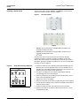
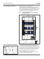
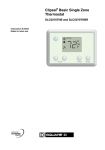
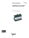
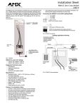
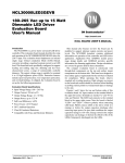
1
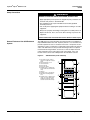
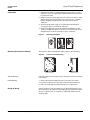
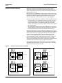
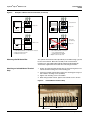
63249-420-208A1
06/2006
La Vergne, TN
Instruction Bulletin
Square D® Clipsal® 36M Enclosure
For Square D Clipsal DIN-Mounted C-Bus™ Modules
Retain for future use.
This bulletin contains instructions for installation of the Square D® Clipsal®
36M enclosure and accessories. The 36M enclosure provides three rows for
mounting Clipsal DIN-mounted C-Bus™ units. Each row has the capacity to
hold one 12M unit, one 8M unit plus one 4M unit, or three 4M units.
Introduction
Item
Part No.
Enclosure
Cabinet, 40 in.
SLC36C
Mounting pan and cover assemblies a
with gray flush-mount cover
with gray surface-mount cover
with white flush-mount cover
SLC36MFG
SLC36MSG
SLC36MFW
Enclosure Accessories
Neutral bar, 18 terminal b, c, d
PK18GTA
Neutral insulator kit
PKGTAB
Ground bar, 23 terminal e
Isolated neutral terminal strip, 10 position
The enclosure system (see Figure 1) consists of a cabinet ➀, a mounting
pan assembly ➁, and a cover assembly ➂. The cabinet is ordered
separately, allowing it to be installed beforehand for rough-in of field wiring.
The mounting pan and cover assemblies are shipped together, and include
the accessories described in footnote a in the table at left. The table also
lists optional accessories that can be ordered to meet the needs of a
particular installation.
Figure 1:
Clipsal 36M Enclosure System
➀
PK23GTA
c, f
SLCNT10
Power Outlets
Two duplex receptacles
SDM4AC
Four duplex receptacles
SDM8AC
➁
Miscellaneous
Door latch, locking
PK4FL
Filler plate, 4M
SLC4CSF8
L barrier g
SLC36LB
a
The mounting pan assembly and cover assembly are
ordered as a single part number (SLC36Mkk). The mounting
pan assembly comes with one L barrier, one ground bar,
four horizontal barriers, and three DIN rails pre-installed.
Also included are two 10-32 x 0.31 in. pan mounting screws
and six horizontal barrier covers. The cover assembly
includes six 10-32 x 0.59 in. mounting screws.
b
Requires one neutral bar insulator kit (PKGTAB).
c
Maximum of four neutral terminal bars (two at top, two at
bottom). Use neutral terminal bars in common neutral
applications.
d
Mixing of neutral terminal bars and isolated neutral terminal
strips is permitted. Mixing permits an additional bar at both
top and bottom (three at top and three at bottom).
e
One ground bar comes pre-installed. The pan will accept up
to two additional ground bars.
f
Maximum of four isolated neutral terminal strips (two at top,
two at bottom). Isolated neutral terminal strips allow
individual neutrals to be maintained.
g
A second L barrier is required when neutral terminal bars or
strips are mounted in both ends of the enclosure. A second
L barrier cannot be used if a duplex power outlet (SDM4AC
or SDM8AC) is installed.
➂
Square D® Clipsal® 36M Enclosure
63249-420-208A1
06/2006
Safety Precautions
DANGER
HAZARD OF ELECTRIC SHOCK, EXPLOSION, OR ARC FLASH
• Apply appropriate personal protective equipment (PPE) and follow safe
electrical work practices. See NFPA 70E.
• This equipment must only be installed and serviced by qualified
electrical personnel.
• Turn off all power supplying this equipment before working on or inside
equipment.
• Always use a properly rated voltage sensing device to confirm power is off.
• Replace all devices, doors, and covers before turning on power to this
equipment.
Failure to follow this instruction will result in death or serious injury.
General Features of the 36M Enclosure
System
The 36M enclosure system provides convenient features for installation of
Clipsal DIN-Mounted C-Bus units. A primary feature is a set of barriers that
provide separation of Class 2 conductors from Class 1 and power circuits.
Separation of Class 2 conductors is required by national and local electrical
codes. The 36M enclosure also provides mounting locations for optional
neutral terminal and ground bar accessories, as well as duplex electrical
outlets required to power some Clipsal units. The number, style, and
location of these accessories will depend on the installation scenario.
Figure 2:
➀
➁
➂
➃
➄
➅
➆
➇
➈
➉
36M Enclosure (cover removed)
Reversible L barrier, defines
either left or right side as Class 2
gutter
Horizontal barrier covers
Horizontal barrier
Enclosure pan
Enclosure cabinet
Mounting area for neutral bars
and/or isolated neutral terminal
strips
DIN unit
Mounting area for ground bars
DIN rail for mounting Clipsal
units
Mounting area for duplex power
outlet or second L barrier and
additional neutral bars and/or
isolated neutral terminal strips
➀
C
L
A
S
S
2
➅
➆
➁
➇
➂
➃
➄
2
➈
➉
© 2006 Schneider Electric All Rights Reserved
Square D® Clipsal® 36M Enclosure
63249-420-208A1
06/2006
Preparation
1. Determine the wiring or conduit requirements for the Class 2, Class 1,
and power circuits, as required by the National Electrical Code and any
local electrical codes.
2. Designate either the left or right side of the enclosure for Class 2 wiring.
When installing the enclosure adjacent to a load center, it is typically
better to designate the side closest to the load center for power
conductors.
3. Select the proper cable clamp, or use other approved methods for
securing the cable or conduit to the enclosure.
4. Remove the appropriate knockouts required for installation of cable
clamps or conduit (see Figure 3). Be sure to reserve knockouts on the
designated Class 2 side for entry/exit of class 2 conductors.
Figure 3:
Mounting the Enclosure Cabinet
Removing Knockouts
The enclosure cabinet is designed for either surface or flush mounting
Figure 4:
Surface or Flush Mounting
Surface Mounting
Flush Mounting
Surface Mounting
Fasten the cabinet to the wall with screws. Use the pre-cut holes in the back
of the cabinet.
Flush Mounting
1. Remove the small mounting knockouts on the side of the cabinet.
2. Position the cabinet so the front edge is flush with the finished wall.
3. Nail or screw through the small knockouts on the cabinet sides.
Rough-In Wiring
© 2006 Schneider Electric All Rights Reserved
Pull the conductor(s) into the cabinet. Use an approved method to secure
the conductor(s) to the cabinet to avoid damage to the conductor insulation.
Be sure to separate Class 2 conductors as required by national or local
electrical codes.
3
Square D® Clipsal® 36M Enclosure
Mounting the Pan Assembly
63249-420-208A1
06/2006
The pan assembly consists of one L barrier, four horizontal barriers, three
DIN rails, and one ground bar pre-installed in a mounting pan. The pan
assembly is typically mounted into the cabinet with the factory-installed
L barrier positioned at the top.
1. Insert the pan assembly into the cabinet.
2. Line up the uppermost mounting hole on the pan with its corresponding
hole in the cabinet.
3. Insert a 10-32 x 0.31 in. mounting screw (included) into the uppermost
mounting hole and tighten to 25–30 lb-in.
4. Line up the mounting hole located next to the uppermost DIN rail with its
corresponding hole in the cabinet.
5. Insert a 10-32 x 0.31 in. mounting screw (included) into the mounting
hole and tighten to 25–30 lb-in.
Figure 5:
Pan Assembly Details
L barrier
Mounting holes
10-32 x 0.31 in.
mounting screws
DIN rail
Horizontal barrier
Changing the Position of the L Barrier
NOTE: NEC Article 725 requires separation
of Class 2 conductors. Class 2 conductors
are permitted within the same enclosure as
Class 1 and power conductors provided
that they are either separated by barriers or
routed to maintain separation of at least
0.25 in. (6 mm). Refer to national and local
electrical codes for complete information.
The L barrier is reversible to create either a left or right side Class 2 gutter.
To reverse the position of the L barrier, unscrew it from the pan and pivot it
to align one side of the L vertically along the designated Class 2 gutter.
Replace the screws and tighten to 25–30 lb-in. Move any installed ground
bars to the gutter on the opposite side of the enclosure, that is, to the gutter
now designated as Class 1.
The L barrier may also be relocated to the opposite end of the enclosure for
bottom-fed applications. Ground bars would not have to be moved unless
you are also changing the side on which the L barrier is located.
Adding a Second L Barrier
An optional second L barrier (SLC36LB) may be required if you are planning
to mount neutral terminals at both ends of the enclosure. To install, position
the second L barrier at the bottom of the enclosure, aligning one side of the
L vertically along the designated Class 2 gutter. Secure with screws
provided in the L barrier kit. Tighten screws to 25–30 lb-in.
Attaching Ground Bars
Optional ground bars may be required to provide additional ground
terminals for attached loads. Mounting holes are provided in both left and
right gutters. Install ground bars in the designated Class 1 gutter. See
bulletin 40271-790-01, Equipment Grounding Bar Kit, supplied with the
grounding bar for mounting instructions.
4
© 2006 Schneider Electric All Rights Reserved
Square D® Clipsal® 36M Enclosure
63249-420-208A1
06/2006
Selection of Neutral Terminals
NOTE: The information presented here describes several possible
approaches for neutral circuits when using the 36M enclosure. Be sure to
follow all national and local electrical codes when installing and wiring the
Square D Clipsal system.
The enclosure is not supplied with neutral terminals. Neutral terminals are
not required for load neutrals that are terminated in the load center. Neutral
terminals are required if neutral conductors terminate in the enclosure.
Select the proper type neutral terminal accessory for your application.
Two types of neutral terminals are available for use with the 36M enclosure:
•
A solid neutral bar is recommended for situations in which more than
one load is fed from the same neutral circuit. Electrical codes do not
permit neutral conductors from different circuits to be connected in
parallel. The neutral bar consists of two plastic standoffs and a solid bus
bar, sold separately.
•
An isolated neutral terminal strip provides isolated pairs of terminals to
maintain individual neutral circuits from the load back to the load center.
Each terminal pair functions like a permanently mounted wire nut.
The following illustrations use Clipsal DIN relay and dimmer units to show
methods of neutral circuit termination and the proper application of solid and
isolated neutral terminals. A single Clipsal DIN unit and a small number of
loads are shown for simplicity. Relay units have isolated pairs of relay
contacts. In many applications the line side of several relays will be
connected together to share a common feed circuit. However, unless all
relays are connected to share a common feed circuit, a relay unit will
receive power from multiple feed circuits. In comparison, all output channels
of a dimmer unit receive power from one common line terminal.
The methods described can be mixed in within an enclosure installation
provided that the wiring practices follow the concepts shown, and comply
with all national and local electrical codes.
Figure 6:
Examples of Neutral Circuit Termination
Relay Unit
Load Center
ON
ON
ON
OFF
OFF
120V
OFF
120V
36M Enclosure
120V
ON
ON
ON
OFF
OFF
OFF
120V
120V
120V
Relay Unit
Load Center
36M Enclosure
Dimmer Unit
Load Center
•
•
•
36M Enclosure
Load circuits pulled to load center
Switch loop to enclosure
Neutral bar in load center
© 2006 Schneider Electric All Rights Reserved
ON
OFF
120V
ON
OFF
120V
Dimmer Unit
Load Center
•
•
•
36M Enclosure
Load circuits pulled to enclosure
Neutral conductors pass through enclosure
Neutral bar in load center
5
Square D® Clipsal® 36M Enclosure
Figure 5:
63249-420-208A1
06/2006
Examples of Neutral Circuit Termination (continued)
Isolated Neutral
Relay Unit
Load Center
36M Enclosure
ON
ON
ON
OFF
OFF
OFF
120V
120V
120V
ON
OFF
120V
Relay Unit
Load Center
36M Enclosure
Neutral Bar
(not allowed)
Dimmer Unit
Load Center
•
•
•
•
36M Enclosure
ON
ON
ON
OFF
OFF
OFF
120V
120V
120V
ON
OFF
120V
Relay Unit
Load Center
Load circuits pulled to enclosure
Load neutrals terminate on neutral bar in enclosure
Single feed from load center
Neutral bar in enclosure
•
•
•
36M Enclosure
Load circuits pulled to enclosure
Load neutrals terminate in enclosure
— Use isolated terminal strip
— Parallel neutrals not allowed
Multiple feed from load center
Attaching a Solid Neutral Bar
The optional solid neutral terminal (SLCNT10) is assembled using a ground
bar and an insulator kit. Mount the assembly in the neutral terminal
mounting area. See bulletin 40271-892-02, Equipment Grounding Bar
Insulator Kit, supplied with the insulator kit for mounting instructions.
Attaching an Isolated Neutral Terminal
Strip
1. Position the isolated neutral terminal strip over the mounting holes in the
neutral terminal mounting area of the mounting pan.
2. Fasten the isolated neutral terminal strip to the mounting pan using four
8-32 x 0.50 in. mounting screws (included).
3. Tighten each mounting screw to 25–30 lb-in.
4. When wiring isolated neutrals, tighten each terminal screw to 16 lb-in.
Figure 6:
Isolated Neutral Terminal Strip
Terminal screw
Mounting screws
6
© 2006 Schneider Electric All Rights Reserved
Square D® Clipsal® 36M Enclosure
63249-420-208A1
06/2006
Installing a Power Outlet
The AC power outlets (models SDM8AC and SDM4AC) mount inside the
enclosure to provide a location for power supplies.
Figure 7:
AC Power Outlets
SDM4AC
SDM8AC
•
SDM4AC will accommodate two standard duplex receptacles (not
included), providing four outlets
•
SDM8AC will accommodate four standard duplex receptacles (not
included), providing eight outlets
•
UL® Listed
The AC power outlet is easily mounted into the enclosure using the
hardware provided. It is typically mounted in the bottom corner of the
Class 2 side of the enclosure. Low voltage wires exit the AC power outlet
through the grommets provided. The grommets can be cut to accommodate
the wiring as shown in Figure 8.
Figure 8:
Outlet Detail Showing Grommets
Grommet cut for wiring
1. Position the outlet box in the desired location within the 36M enclosure.
Orient the box so that the grommet side is closest to the DIN rails. For
example, if the outlet will be mounted in the bottom of the enclosure, the
grommet side of the outlet box will be pointing up.
2. Line up the mounting holes on the back of the outlet box with their
corresponding holes on the mounting pan.
3. Attach the outlet box to the mounting pan with four #6 x 0.25 in. sheet
metal screws included with the outlet.
4. Tighten each screw to 22–26 lb-in.
U
L
Part no.: 123-456
5. Attach the receptacles to the outlet face plate using the screws supplied.
AC ADAPTOR
OEM
6. Connect AC power wiring to each receptacle in compliance with national
and local electrical codes.
7. Position the outlet face plate and receptacles over the outlet box.
8. Attach the face plate to the outlet box with four 6-32 x 0.25 in. screws
included with the outlet.
© 2006 Schneider Electric All Rights Reserved
7
Square D® Clipsal® 36M Enclosure
Installing DIN-Mounted C-Bus Units
63249-420-208A1
06/2006
1. Determine locations for each Clipsal DIN unit:
Most Clipsal DIN units use wiring terminals that are positioned inside the
channel created by the horizontal barrier. Depending on the unit
selected and the application, the connected wiring will be either Class 1
or Class 2. The horizontal barrier will maintain separation of circuits
between rows of units. It is ideal to position all units with the same
connection type in the same row. See Figure 9.
Figure 9:
C-Bus Unit Installation Example (L barrier shown in
optional configuration)
PC Interface
Power Supply
Class 2
Class 1 and Power
Analog Output
Barriers
KEY: Wiring Type
8 Channel Dimmer
Class 1
General Input
Plug Pack
Figure 10:
Mounting C-Bus Unit on DIN Rail
C-Bus unit
3.
1.
For installations in which Class 1 and Class 2 conductors will be present
in the same horizontal channel, locate units requiring Class 2
connections nearest to the designated Class 2 gutter. This will prevent
crossing of Class 1 and Class 2 conductors in the horizontal channel
and make it possible to route wires to maintain physical separation of at
least 0.25 inches as required by national and local electrical codes.
2. Install the C-Bus DIN-mounted units on the DIN rail using the
instructions supplied with the units. See Figure 10.
DIN rail
2.
8
Class 2
3. Refer to the installation instructions supplied with the DIN-mounted
C-Bus units for additional wiring instructions.
© 2006 Schneider Electric All Rights Reserved
Square D® Clipsal® 36M Enclosure
63249-420-208A1
06/2006
Installing Horizontal Barrier Covers
Six horizontal barrier covers are provided with the 36M enclosure system.
Each cover has a series of tabs that allow the cover to be snapped onto a
horizontal barrier.
The top and bottom barriers are each shielded by a single cover. The middle
two barriers are each shielded by two covers interlocked together, as shown
in Figure 11.
Figure 11:
Installation of Horizontal Barrier Covers
Barrier
cover
Horizontal
barrier
Connect Communication Cables
Each Clipsal DIN-Mounted unit has a pair of RJ-45 jacks for connecting the
Class 2 C-Bus network. Connect all units together using the C-Bus jumper
assemblies provided with the units. Also connect the C-Bus cable that exits
the enclosure to an open RJ-45 C-Bus jack. Connect other communication
cables to units that have other types of communication ports, such as an
RS232 connection to a computer, or an Ethernet connection to a local area
network.
NOTE: All communication cable connections must be made after the barrier
cover is installed, and must be unplugged to remove the barrier cover.
Installing the Filler Plate
Install filler plate(s) (SLC4CSF8) to close openings on the cover assembly
where Clipsal DIN-Mounted units are not installed. See bulletin
63249-420-217A1, Square D® Clipsal® DIN Enclosure Filler Plate, supplied
with the filler plate for installation instructions.
Installing a Locking Door Latch
The cover assembly is shipped with a non-locking door latch. A locking
door latch (PK4FL) is available as an optional accessory. To replace the
door latch:
1. Completely loosen the two door latch screws and remove the existing
door latch.
2. Position the new door latch in the same location as the one removed.
3. Fasten with the two screws removed in step 1, or with the screws
supplied with the new latch.
4. Tighten each screw to 20–30 lb-in.
Attaching the Cover Assembly
© 2006 Schneider Electric All Rights Reserved
Once the installation is complete, place the cover assembly on the cabinet
and fasten securely, using the six 10-32 x 0.59 in. machine screws
provided. Tighten each screw to 30 lb-in.
9
Square D® Clipsal® 36M Enclosure
Instruction Bulletin
Schneider Electric USA
295 Tech Park Drive, Suite 100
La Vergne, TN 37086
(615) 287-3400
www.SquareDLightingControl.com
63249-420-208A1
06/2006
Square D,
, Clipsal, and C-Bus are trademarks or registered trademarks of Schneider Electric
and/or its affiliates in the United States and/or other countries.
Electrical equipment should be installed, operated, serviced, and maintained only by qualified
personnel. No responsibility is assumed by Schneider Electric for any consequences arising out of
the use of this material.
© 2006 Schneider Electric All Rights Reserved