1
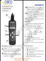
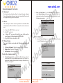
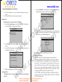
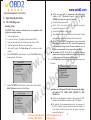
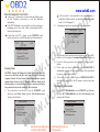
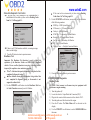
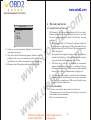
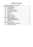
www.uobd2.com
m
o
c
.
2
d
b
o
m
u
.
o
c
w
.
w
2
d
w
b
o
u
.
w
w
w
OBDII Code Scanner
( CAN+VW/AUDI )
Manual
E-Mail:[email protected] MSN:[email protected]
Tel:0086-13986168065
SKYPE:greebid6
www.uobd2.com
m
o
c
.
2
d
b
o
m
u
.
o
c
w
.
w
2
d
w
b
o
u
.
w
w
w
Table of Contents
1. Safety Precautions and Warnings ......................................2
2. Product Information
2.1 Tool Description .............................................................3
2.2 Specifications .................................................................4
2.3 Accessories Included ......................................................4
2.4 Navigation Characters ....................................................4
2.5 Keyboard ........................................................................5
2.6 Power ..............................................................................5
2.7 Product Setup ..................................................................5
2.8 Vehicle Coverage ...........................................................8
3. Operating Instructions
3.1 VW/AUDI Diagnostics ..................................................9
3.2 OBDII/EOBD Diagnostics ..........................................14
3.3 Oil Reset .......................................................................18
4. Warranty and Service ........................................................20
1
1. Safety Precautions and Warnings
To prevent personal injury or damage to vehicles and/or the scan
tool, read this instruction manual first and observe the following
safety precautions at a minimum whenever working on a vehicle:
Always perform automotive testing in a safe environment.
Wear safety eye protection that meets ANSI standards.
Keep clothing, hair, hands, tools, test equipment, etc,away from
all moving or hot engine parts.
Operate the vehicle in a well-ventilated work area; Exhaust gases
are poisonous.
Put blocks on drive wheels and never leave vehicle unattended
while running tests.
Use extreme caution when working around the ignition coil,
distributor cap, ignition wires and spark plugs. These components
create hazardous voltages when the engine isrunning.
Put transmission in PARK (for automatic transmission) or
NEUTRAL (for manual transmission) and make sure the parking
brake is engaged.
Keep a fire extinguisher suitable for gasoline/chemical/electrical
fires nearby.
,
Don t connect or disconnect any test equipment with ignition on
or engine running.
Keep the scan tool dry, clean and free from oil, water and grease.
Use a mild detergent on a clean cloth to clean the outside of the
scan tool, when necessary.
E-Mail:[email protected] MSN:[email protected]
Tel:0086-13986168065
SKYPE:greebid6
2
www.uobd2.com
2. Product Information
2.1 Tool Description
6
m
o
c
.
2
d
b
o
m
u
.
o
c
w
.
w
2
d
w
b
o
u
.
w
w
w
UP SCROLL BUTTON -- Moves up through menu and
submenu items in menu mode. When more than one DTC is
retrieved, m ove s up through the current screen to the previous
screens for additional DTCs and definitions.
DOWN SCROLL BUTTON -- Moves down th rough menu
and submenu items in menu mode. When m ore than one DTC is
retrieved, moves down through the current screen to the next
screens for additional DTCs and definitions.
,
OBD II CONNECTOR -- Connects the scan tool to the vehicle s
Data Link Connector (DLC).
2.2 Specifications
1)
2)
3)
4)
5)
1
4
2
3
Display: Backlit, 128 x 64 pixel display with contrast adjustment
Operating Temperature: 0 to 50 (32 to 122 F )
Storage Temperature: -20 to 70 (-4 to 158 F )
External Power: 8.0 to 15.0 Volts provided via vehicle battery
Dimensions:
Length
Width
Height
178 mm (7.00 )
95 mm (3.75 )
34 mm (1.35 )
6) NW: 0.70kg(1.54lb), GW: 1.0kg(2.20lb)
2.3 Accessories Included
1)
2)
5
3)
LCD DISPLAY -- Indicates test results. Backlit, 128 x 64 pixel
display with contrast adjustment.
Y BUTTON -- Confirms a selection (or ac tion ) from a menu.
,
When a DTC s definition covers more than one screen, it is used
to move down to the next screen for additional data.
N BUTTON -- Cancels a selection (or action) from a menu or
returns to the menu. It is also used to setup the unit when being
pressed and held for at least 3seconds.
3
User,s Manual -- Instructions on tool o perations
OBD2 cable -- Provides Power to tool and communicates
between tool and vehicle
Carry Case -- A nylon case to store the scan tool when not i n use
2.4 Navigation Characters
Characters used to help navigate the sc an tool are:
1)
-- Indicate s current selection.
2)
-- A flashing Down Arrow indicates additional information is
available on the next screen.
3)
-- A flashing UP Arrow indicates additional information is
available on the previous screen.
4) Pd -- Identifying a Pending D TC when viewing DTCs.
4
E-Mail:[email protected] MSN:[email protected]
Tel:0086-13986168065
SKYPE:greebid6
www.uobd2.com
2.5 Keyboard
m
o
c
.
2
d
b
o
m
u
.
o
c
w
.
w
2
d
w
b
o
u
.
w
w
w
No solvents such as alcohol are allowed to clean the keypad or display.
Use a mild nonabrasive deter gent and a soft cotton cloth. Do not soak
the keypad as the keypad is not waterproof.
2) From the Main Menu: Use the UP/DOWN Scroll Buttons to
select System Setup and then press the Y button. Follow the
instructions to make ad justments and settings a s described in the
following setup options.
Main Menu
2.6 Power
The external power of the scan tool is provided via the vehicle Data
Link Conncctor (DLC). Just follow the steps below to turn on the sca n
tool:
1) Connect the OBD II Cable to scan tool.
2) Find DLC on vehicle.
A plastic DLC cover may be found for some vehicles and you
need to remove it before plugging the OBD2 cable.
3) Plug OBD II Cable to the vehicle,s DLC.
2.7 Product Setup
The scan tool allows you to make the following adjustments and
settings:
1) Contrast adjustment: Adjusts the contrast of the LCD display.
2) Display Test: Tests the LCD display.
3) Keyboard test: Tests the keyboard.
To enter the setup menu mode
1) VW/AUDI
2) OBDII/EOBD
3) Oil Reset
4) System Setup
Contrast Adjustment
1) From the System Setup menu, use the UP/DOWN scroll buttons
to select Contrast, and press the Y button.
System Setup
1) Contrast
2) Display Test
3) Keyboard Test
1) From the keyboard: Press and hold the N button for at least 3
seconds until the System Setup menu shows up. Follow the
instructions to make adjustments and settings as described in the
following setup options.
System Setup
1) Contrast
2) Display Test
3) Keyboard Test
Contrast
Contrast ( 45% )
Use
5
E-Mail:[email protected] MSN:[email protected]
Tel:0086-13986168065
SKYPE:greebid6
or
to change
6
www.uobd2.com
m
o
c
.
2
d
b
o
m
u
.
o
c
w
.
w
2
d
w
b
o
u
.
w
w
w
3) Press the Y button to save your selection and return to previous
menu.
4) Press the N button to return to previous menus.
Display Test
1) Use the UP/DOWN scroll buttons to select Keyboard Test from
the System Setup menu, and then press the Y button.
2) Display Test
3) Keyboard Test
The Display Test is used to check the LCD display.
1) From the System Setup menu, use the UP/DOWN scroll buttons
to select Display Test and press the Y button.
System Setup
1) Contrast
2) Display Test
3) Keyboard Test
2) Press any key to start test. When you press a key, the key name
should be o bserved on the display. If the name does not sho w up,
then the key is not functioning properly.
Press any key to
Start test to
display name.
2) Select Display Test from the Display Test menu and press the Y
button.
3) Press the Y button again to start test. Look for missing spots in
the solid black characters.
Display Test
Press [Y] to test.
Key:
Double [N] to Return
3) Double press N to return to the previous menu.
2.8 Vehicle Coverage
The VAG Scanner is specially designed to work with most
Volkswagen and Audis sold worldwide of 1990 or newer models.
spots in characters.
If a VW / AUDI has a 16-pin OBD - II style Data Link Connector (DTC), the code reader will certainly work. If it has an oldstyle 2x2 Data Link Connector (DTC), then it depends on whether
Press <N> to return.
there are 4 or 3 wires connecting to the pins. If there are 4 wires,
each connecting a pin, then it will work. If there are only 3 wires,
4) When completed, press the N button to return.
leaving one pin disconnected, then it will not work.
Keyboard Test
For VW/AUDI with old-style 2x2 Data Link Conneetor (DTC),
The Keyboard Test is us ed to verify that the keys are functioning
you need to have a 2x2 cabling adapter which is not included
properly.
in this product package.
7
8
E-Mail:[email protected] MSN:[email protected]
Tel:0086-13986168065
SKYPE:greebid6
Look for missing
www.uobd2.com
m
o
c
.
2
d
b
o
m
u
.
o
c
w
.
w
2
d
w
b
o
u
.
w
w
w
3. Operating Instructions
3.1 VW/AUDI Diagnostics
Reading Codes
,
CAUTION: Don t connect or disconnect any test equipment with
ignition on or engine running .
1) Turn the ignition off.
,
2) Locate the vehicle s 16-pin Data Link Connector (DLC).
3) Plug into the scan tool cable connector to the vehicle,s DLC.
4) Turn the ignition on. But do not start the engine.
5) Press the Y button. The Main Menu will be observed on the
display.
6) Use the UP/DOWN scroll buttons to select VW/AUDI from the
menu and press the Y button.
Main Menu
1) VW/AUDI
2) OBDII/EOBD
3) Oil Reset
4) System Setup
7)
1) Read Codes
2) Erase Codes
3) ECU Information
4) Readiness Test
Use the UP/DOWN scroll buttons to select the syst em from the
Select System menu and press the Y button.
Select System
01) Engine
02) Auto Trans
15) Airbags
03) ABS Brakes
08) Auto HVAC
09) Cent. Elect.
9
8)
If the scan tool fails to communicate with the selected
,
vehicle s ECU (Electronic Control Unit), a LINK
ERROR! message shows up on the display.
Verify that the ignition is ON;
Check if the scan tool,s OBD II connector is securely
connected to the vehicle,s DLC;
Verify that the module is supported;
Turn the ignition off and wait for about 10 seconds. Turn the
ignition back to on and repeat the procedure from step 5.
If the LINK ERROR message does not go away, then
there might be problems for the s can tool to communicate
with the module being tested. The most common cause is
that the scanned module is not supported on the vehicle.
The numbers (01, 02, 15, 03, 08, etc) in front of the system
names refer to the physcal addresses assigned to the systems,
not the sequence of the systems to be arranged.
Select Read Codes from the Select Funciton menu and press the
Y button.
Select Function
If there are no Diagnostic Trouble Codes present, the display
will indicate NO CODES ARE STORED IN THE
MODULE!
If there are any Diagnostic Trouble Codes present, the DTC
number and its definition will show on the LCD display.
The subcode, the communication protocol, the sequence of
the DTC currently being observed and the total number of
codes detected will be observed on the upper right hand
corner of the display.
10
E-Mail:[email protected] MSN:[email protected]
Tel:0086-13986168065
SKYPE:greebid6
www.uobd2.com
m
o
c
.
2
d
b
o
m
u
.
o
c
w
.
w
2
d
w
b
o
u
.
w
w
w
,
When a DTC s definition covers more than one display screen,
use the Y button, as necessary, to view any additional
information.
If the DTC definition is not available, an advisory message
prompting you to refer to the vehicle service manual will be
observed on the display.
2)
If the scan tool is not connected or no communication is
established with the vehicle yet, then refer to Reading Codes
from 1 to 7 at Patagraph 3.1.
A warning message comes up asking for your confirmaton.
Erase Codes
Erase Trouble Codes!
Are you sure?
If more than one DTC is found, use the UP/DOWN scroll
buttons, as necessary, until all the codes have been shown up.
16627 --100
CAN BUS
<YES>
01/10
Solenoid Valve(A)
For Boost Pressure
Control(N75):
Malfunction: P0243
3)
4)
Erasing Codes
5)
CAUTION: Erasing the Diagnostic Trouble Codes may allow the
scan tool to delete not only the codes from the vehicle ,s on-board
computer, but also Freeze Frame data and manufacturer specific
enhanced data. Further, the I/M Readiness Monitor Status for all
vehicle monitors is reset to Fail status. Do not erase the codes before
the system has been checked completely by a technician.
1) If you decide to erase the DTCs, use the UP/DOWN scroll
buttons to select Erase Codes from the Select Function menu
and press the Y button.
6)
If you do not want to proceed with erasing the codes, press the N
button.to exit. A message of command cancelled will show up.
If you do wish to proceed to erase the codes, then press the Y
button.
If the codes are clea red successfully, an ERASE DONE !
confirmation messa ge will show on the display. Press any button
to return to the previous menus.
If the codes are not cleated, then an ERASE FAILURE!
message will appear. Press the N button to return to previous
menus.
Viewing ECU Information
1) To view ECU Information , use the UP/DOWN scroll buttons
to select ECU Information from the Select Function menu
and press the Y button.
Select Function
Select Function
1) Reade Codes
2) Erase Codes
3) ECU Information
4) Readiness Test
1) Reade Codes
2) Erase Codes
3) ECU Information
4) Readiness Test
11
NO
E-Mail:[email protected] MSN:[email protected]
Tel:0086-13986168065
SKYPE:greebid6
12
www.uobd2.com
m
o
c
.
2
d
b
o
m
u
.
o
c
w
.
w
2
d
w
b
o
u
.
w
w
w
If the scan tool is not connected or no communication is
established with t he vehicle yet, then refer to Reading Codes
from 1 to 7 at Paragr aph 3.1.
VAG No.: 06A906032TF
Component:
Bosch
1.815VT
0020
Coding: 0008570
Imp:
0000 WSC: 000078
If there is no ECU Information available, a warning message
shows on the display.
2) Press the N button to return to previous menus.
Readiness Test
Important: The Readiness Test function is used to check the
operations of the Emission Svstem on OBD2/EOBD compliant
vehicles. It is an excellent function to use prior to having a vehicle
inspected for compliance to an emissions program.
Pass -- Indicates that a particular monitor being checked has
completed its diagnostic t esting.
Fail -- Indicates that a particular monitor bein g checked has
not completed its diagnosti c testing or the monitor is not
supported on that vehicle.
1) Use the UP/DOWN scroll buttons to select Readiness Test from
the Select Function menu and press the Y button.
1) Reade Codes
2) Erase Codes
3) ECU Information
4) Readiness Test
13
If the scan tool is not connected yet, then refer to Reading
Codes from 1 to 7 at Paragr aph 3.1.
2) Use the UP/DOWN scroll buttons, as necessary, to view the status
of the following monitors:
EGR Sys.-- EGR System Monitor
O2 Sensor(s) -- O2 Sensors Monitor
Catalyst -- Catalyst Monitor
EVAP Sy s. -- Evaporative System Monitor
Heated O2 --O2 Sensor Heater Monitor
Sec Air Inject -- Secondary Air Monitor
A/C -- A/C system Monitor
Catalytic Conv. -- Catalytic Convertor Monitor
Readiness Test
EGR Sys.
Heated O2
O2 Sensor(s)
A/C
Sec. Air Inject
EVAP Sys.
3)
Pass
Pass
Pass
Pass
Pass
Fail
Press the N button to return to previous menus.
3.2 OBDII/EOBD Diagnostics
Reading Codes
,
CAUTION: Don t connect or disconnect any test equipment with
ignition on or engine running.
1) Turn the ignition off.
,
2) Locate the vehicle s 16-pin Data Link Connector (DLC).
,
3) Plug into the scan tool cable connector to the vehicle s DLC.
4) Turn the ignition on. But do not start the engine.
5) Press the Y button. The Main Menu will be observed on the
display.
6) Use the UP/DOWN scroll buttons to select OBDII/EOBD from
the menu.
14
E-Mail:[email protected] MSN:[email protected]
Tel:0086-13986168065
SKYPE:greebid6
www.uobd2.com
m
o
c
.
2
d
b
o
m
u
.
o
c
w
.
w
2
d
w
b
o
u
.
w
w
w
OBDII/EOBD Diag.
Main Menu
1) Read Codes
2) Erase Codes
1) VW/AUDI
2) OBDII/EOBD
3) Oil Reset
4) System Setup
7) Press the Y button. A sequence of messages showing the
OBDII/EOBD protocols will be observed on the display until the
vehicle protocol is detected.
If the scan tool fail s to communicate with the vehicle,s ECU
(Engine Control Unit), a LINK ERROR! message shows
up on the display.
Verify that the ignition is ON;
,
Check if the scan tool s OBD II connector is securely
connected to the vehiclc ,s DLC;
Verify that the vehicle is OBDII/EOBD compliant;
Turn the ignition off and wait for about 1 0 seconds. Turn the
ignition back to on and repeat the procedure from step 5.
If the LINK ERROR message does not go away, then there
might be proble ms for the scan tool to communicate with the
vehicle. Contact your local distributor or the manufactur er ,s
customer service department for assistance.
8) After the vehicle protocol is displayed on the screen, press any key or
wait about2 seconds for the OBDII/EOBD Diag menu to come up.
9) Use the UP/DOWN scroll buttons to select Read Codes from the
menu and press the Y button.
15
If there are no Diagnostic Trouble Codes present, the display
will indicate NO CODES ARE STORED IN THE
MODULE!
If there are an y Diagnostic Trouble Codes present, the F ault
Codes and Pending Co des w ill be reported on the display.
P0118
Pd
ISO9141
06/06
$09
Pressure Control
Solenoid A Control
Circuit Low
The DTC number will appear on the upper left hand corner
and its definition will show on the body of screen.
The type of code (Generic or Manufacturer specific), the
vehicle protocol, the sequence of the DTC currently being
observed, the total number of codes detected and the module
ID will be observed on the upper right hand corner of the
display.
If the code being di splayed is a pending code, the Pd icon will
be observ ed next to the DTC number on th e u pper right hand
corner of the display.
,
When a DTC s definition covers more than one display screen,
use the Y button, as necessary, to view any additional
information.
16
E-Mail:[email protected] MSN:[email protected]
Tel:0086-13986168065
SKYPE:greebid6
www.uobd2.com
m
o
c
.
2
d
b
o
m
u
.
o
c
w
.
w
2
d
w
b
o
u
.
w
w
w
If the retrieved DTCs contain any manufacturer specific or
enhanced codes, you will be prompted to refer to the CD DTC
library or the vehicle service manual to view the DTC
definitions.
10) If more than one DTC is found, use the UP/DOWN scroll buttons,
as necessary, until all the codes have been shown up.
Erasing Codes
1)
If you decide to erase the DTCs, use the UP/DOWN scroll
buttons to select Erase Codes from the OBDII/EOBD Diag, menu
and press the Y button.
OBDII/EOBD Diag.
1) Read Codes
2) Erase Codes
If the scan tool is not connected or no communication is
established with the vehicle yet, then refer to Reading Codes
from 1 to 8 at Paragraph 3.2.
2) A warning message comes up asking for your confirmation.
Erase Codes
4) If you do wish to proceed to erase the codes, then press teh Y
button.
5) If the codes are cleared successfully, an ERASE DONE!
confirmation will show on the displ ay. Pres s any button to return
to previous menus.
6) If the codes are not cleared, then an ERASE FAILURE!
message will appear. Press the N button to return to previous
menus.
3.3 Oil Reset
1) Turn the ignition off.
2) Locate the vehicle,s 16-pin Data Link Connector (DLC).
3) Plug into the scan tool cable connector to the vehicle,s DLC.
4) Turn the ignition on. But do not start the engine.
5) Press the Y button. The Main Menu will be observed on the
display.
6) Use the UP/DOWN scroll buttons to select Oil Reset from the
menu. Press the Y button to accept the option and to move to the
next screen.
Main Menu
1) VW/AUDI
2) OBDII/EOBD
3) Oil Reset
4) System Setup
Erase Trouble Codes!
Are you sure?
<YES> NO
7) Do the following to select menu options:
a) Use the UP/DOWN scroll buttons to mov e the c urso r(
select an optian, then
) and
b) Press the Y button to accept the option and to move to the next
screen.
3) If you do not want to proceed with erasing the codes, press the N
button to exit. A message of command cancelled will show up.
c) Repeat a) and b) to select the necessary options.
17
18
E-Mail:[email protected] MSN:[email protected]
Tel:0086-13986168065
SKYPE:greebid6
www.uobd2.com
m
o
c
.
2
d
b
o
m
u
.
o
c
w
.
w
2
d
w
b
o
u
.
w
w
w
4. Warranty and Service
Vehicle Make
1) VW/AUDI
2) AUDE
3) SEAT
4) SKODA
4.1 Limited One Year Warranty
8) Follow any on-screen instructions. Optionally, use the N button to
return to previous screens.
9) If the Service Reset Failed message appea rs, then there might be
problems for the scan tool to communicate with the vehicle being
tested. Refer to the vehicle service manual for more information.
10) When done, turn off the ignition and disconnect the scan tool.
CEM warrants to its customers that this product will be fr ee from all
defects in materials and workmanship for a period of one (1) year from
the date of the original purchase, subject to the following terms and
conditions:
1) The sole responsibility of CEM under the Warranty is limited to
either the repair or, at the option of CEM, replacement of the scan
tool at no charge with Proof of Purchase. The sales receipr may be
used for this purpose.
2) This warranty does not app ly to damages caused by improper use,
accident, flood, lightning, or if the product was altered or repaired
by anyone other than the Manufacturer, Service Center.
3) CEM shall not be liable fo r any incidental or consequential
damages arising from the use, misuse, or mounting of the scan
tool. Some states do not allow limitations on how long an implie d
warranty lasts, so the above limitations m ay not apply to you.
4) All in formation in this manual is based on the latest information
available at the time of publication and no war rant y can be made
for its accuracy or completeness. CEM reserves the right to make
changes at any time without notice.
4.2 Service Procedures
If you have any questions, please contac t y our local store.
If it becomes necessary to return the scan tool for repair, contact your
local distributor for more information.
Http://www.cem-instruments.com
19
E-Mail:[email protected] MSN:[email protected]
Tel:0086-13986168065
SKYPE:greebid6
20