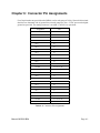
1
ACCES I/O PRODUCTS INC
10623 Roselle Street, San Diego, CA 92121
TEL (858)550-9559
FAX (858)550-7322
MODEL IOD64
USER MANUAL
FILE: MIOD64.B2b
Notice
The information in this document is provided for reference only. ACCES does not assume any liability
arising out of the application or use of the information or products described herein. This document may
contain or reference information and products protected by copyrights or patents and does not convey any
license under the patent rights of ACCES, nor the rights of others.
IBM PC, PC/XT, and PC/AT are registered trademarks of the International Business Machines Corporation.
Printed in USA. Copyright 1995 by ACCES I/O Products Inc, 10623 Roselle Street, San Diego, CA 92121.
All rights reserved.
Page iii
Warranty
Prior to shipment, ACCES equipment is thoroughly inspected and tested to applicable specifications.
However, should equipment failure occur, ACCES assures its customers that prompt service and support
will be available. All equipment originally manufactured by ACCES which is found to be defective will be
repaired or replaced subject to the following considerations.
Terms and Conditions
If a unit is suspected of failure, contact ACCES' Customer Service department. Be prepared to give the unit
model number, serial number, and a description of the failure symptom(s). We may suggest some simple
tests to confirm the failure. We will assign a Return Material Authorization (RMA) number which must
appear on the outer label of the return package. All units/components should be properly packed for handling
and returned with freight prepaid to the ACCES designated Service Center, and will be returned to the
customer's/user's site freight prepaid and invoiced.
Coverage
First Three Years: Returned unit/part will be repaired and/or replaced at ACCES option with no charge for
labor or parts not excluded by warranty. Warranty commences with equipment shipment.
Following Years: Throughout your equipment's lifetime, ACCES stands ready to provide on-site or in-plant
service at reasonable rates similar to those of other manufacturers in the industry.
Equipment Not Manufactured by ACCES
Equipment provided but not manufactured by ACCES is warranted and will be repaired according to the
terms and conditions of the respective equipment manufacturer's warranty.
General
Under this Warranty, liability of ACCES is limited to replacing, repairing or issuing credit (at ACCES
discretion) for any products which are proved to be defective during the warranty period. In no case is
ACCES liable for consequential or special damage arriving from use or misuse of our product. The
customer is responsible for all charges caused by modifications or additions to ACCES equipment not
approved in writing by ACCES or, if in ACCES opinion the equipment has been subjected to abnormal use.
"Abnormal use" for purposes of this warranty is defined as any use to which the equipment is exposed other
than that use specified or intended as evidenced by purchase or sales representation. Other than the above,
no other warranty, expressed or implied, shall apply to any and all such equipment furnished or sold by
ACCES.
Page iv
Table of Contents
Notice . . . . . . . . . . . . . . . . . . . . . . . . . . . . . . . . . . . . . . . . . . . . . . . . . . . . . . . . . . . . . . iii
Warranty . . . . . . . . . . . . . . . . . . . . . . . . . . . . . . . . . . . . . . . . . . . . . . . . . . . . . . . . . . . ii
Chapter 1: Introduction . . . . . . . . . . . . . . . . . . . . . . . . . . . . . . . . . . . . . . . . . . . . . . 1-1
Description . . . . . . . . . . . . . . . . . . . . . . . . . . . . . . . . . . . . . . . . . . . . . . . . . . . . . . . . . . .
Specifications . . . . . . . . . . . . . . . . . . . . . . . . . . . . . . . . . . . . . . . . . . . . . . . . . . . . . . . . .
Input Mode . . . . . . . . . . . . . . . . . . . . . . . . . . . . . . . . . . . . . . . . . . . . . . . . . . . . . . . . . . .
Output Mode . . . . . . . . . . . . . . . . . . . . . . . . . . . . . . . . . . . . . . . . . . . . . . . . . . . . . . . . . .
Logic Voltage Level . . . . . . . . . . . . . . . . . . . . . . . . . . . . . . . . . . . . . . . . . . . . . . . . . . . . .
1-1
1-2
1-5
1-5
1-5
Chapter 2: Installation . . . . . . . . . . . . . . . . . . . . . . . . . . . . . . . . . . . . . . . . . . . . . . 2-1
CD Installation . . . . . . . . . . . . . . . . . . . . . . . . . . . . . . . . . . . . . . . . . . . . . . . . . . . . . . . . .
3.5-Inch Diskette Installation . . . . . . . . . . . . . . . . . . . . . . . . . . . . . . . . . . . . . . . . . . . . . .
Directories Created on the Hard Disk . . . . . . . . . . . . . . . . . . . . . . . . . . . . . . . . . . . . . . .
Installing the Card . . . . . . . . . . . . . . . . . . . . . . . . . . . . . . . . . . . . . . . . . . . . . . . . . . . . . .
2-1
2-1
2-2
2-4
Chapter 3: Option Selection . . . . . . . . . . . . . . . . . . . . . . . . . . . . . . . . . . . . . . . . . . 3-1
Address Selection . . . . . . . . . . . . . . . . . . . . . . . . . . . . . . . . . . . . . . . . . . . . . . . . . . . . . . 3-1
Hardware Interrupts . . . . . . . . . . . . . . . . . . . . . . . . . . . . . . . . . . . . . . . . . . . . . . . . . . . . 3-6
Chapter 4: Software . . . . . . . . . . . . . . . . . . . . . . . . . . . . . . . . . . . . . . . . . . . . . . . . . 4-1
Chapter 5: Programming . . . . . . . . . . . . . . . . . . . . . . . . . . . . . . . . . . . . . . . . . . . . . 5-1
Control Register . . . . . . . . . . . . . . . . . . . . . . . . . . . . . . . . . . . . . . . . . . . . . . . . . . . . . . . 5-1
Port Addresses . . . . . . . . . . . . . . . . . . . . . . . . . . . . . . . . . . . . . . . . . . . . . . . . . . . . . . . . 5-1
Chapter 6: Connector Pin Assignments . . . . . . . . . . . . . . . . . . . . . . . . . . . . . . . . 6-1
Page v
List of Figures
Figure 1-1: IOD64 Block Diagram . . . . . . . . . . . . . . . . . . . . . . . . . . . . . . . . . . . . . . . . . . . . . 1-3
Figure 1-2: Simplified Schematic of the Bi-Directional Data Port . . . . . . . . . . . . . . . . . . . . . 1-4
Figure 3-1: Option Selection Map . . . . . . . . . . . . . . . . . . . . . . . . . . . . . . . . . . . . . . . . . . . . . 3-3
List of Tables
Table 3-1:
Table 3-2:
Table 3-3:
Table 3-4:
Table 5-1:
Table 6-1:
Page vi
Standard Address Assignments for 286/386/486 Isa Bus Computers . . . . . . . . .
I/O Port Start Address . . . . . . . . . . . . . . . . . . . . . . . . . . . . . . . . . . . . . . . . . . . . .
Control Register Address . . . . . . . . . . . . . . . . . . . . . . . . . . . . . . . . . . . . . . . . . .
I/O Port Address Selection . . . . . . . . . . . . . . . . . . . . . . . . . . . . . . . . . . . . . . . . .
Control Register . . . . . . . . . . . . . . . . . . . . . . . . . . . . . . . . . . . . . . . . . . . . . . . . .
Connector Pin Assignments . . . . . . . . . . . . . . . . . . . . . . . . . . . . . . . . . . . . . . . .
3-1
3-4
3-4
3-6
5-1
6-1
Chapter 1: Introduction
Features
•
•
•
•
•
•
•
•
•
64 Channels of Digital Input/Output at Voltages up to 30 VDC.
Eight 8-Bit Ports of Directly Addressable Bi-Directional I/O.
Bit-by-Bit Programmable for Input or Output.
I/O Buffers Can Be Enabled/Disabled under Program Control.
Compatible with Industry Standard I/O Racks.
Standard 50-Conductor Ribbon Cables Connect Directly to I/O Racks.
User Selectable to Occupy any Eight Consecutive I/O Addresses.
Control and I/O Ports Separately Addressable to Allow I/O Ports for Multiple Cards to
Occupy Consecutive Addresses.
Four Inputs may be Directed to Hardware Interrupts.
Description
IOD64 accepts up to 64 bits of digital I/O. The card is organized into eight 8-bit ports and is
designed to provide interface between IBM PC/XT/AT or compatible computers and parallel digital
I/O ports at voltages up to 30 VDC. The card is also completely compatible with industry-standard
optically-isolated I/O Module Mounting Racks (Opto-22 or equivalent). Up to four 16-position I/O
racks can be controlled and each point is directly addressable by the host computer. The racks can
contain either AC or DC, input or output modules in any combination for a total of 64 isolated I/O
points. Also, the connections are compatible with screw terminal accessory cards.
Input/Output wiring connections are via 50-pin headers on the card: one connector per pair of 8-bit
ports. Every second conductor (and thus, every alternate wire in the cable) is grounded to minimize
crosstalk between signals. If needed for external circuits, +5 VDC computer power is available at
pin 49 of each of these connectors.
Caution
If the +5 VDC power is connected to external circuits, total power consumed must not exceed 1
Amp. or else the IOD64 card could be damaged.
Each I/O point is directly addressable by the host computer. Variable I/O-mapped addressing allows
you to select eight consecutive addresses, plus a separate control register, from any I/O addresses
between 200 hex and 3FF hex. In addition, you can drive four of the host computer's interrupts from
points programmed as inputs to IOD64. See the Programming chapter for further details.
Manual MIOD64.B2b
Page 1-1
IOD64 Manual
Specifications
Digital Inputs
•
•
Logic High:
Logic Low :
2.0 to 10 VDC.
-0.5 to +0.8 VDC.
Digital Outputs
•
Logic High:
•
Logic Low :
•
Power Output: +5VDC from computer bus (external 1A fast-blow fuse strongly
recommended).
Size:
13-inches long (330 mm) full size card.
•
Open Collector, Up to 30VDC compliance. If no user-supplied voltage,
outputs are pulled up to 5VDC via 1K ohm resistors.
0.5 VDC max., can sink up to 40 mA.
Environmental
•
•
•
•
Operating Temperature Range:
Storage Temperature Range:
Humidity:
Power Required:
Page 1-2
0 °C. to 60 °C.
-50 °C. to +120 °C.
0 to 90% RH, non-condensing.
+5 VDC at 900 mA (all outputs low).
Manual MIOD64.B2b
Figure 1-1: IOD64 Block Diagram
The Read/Write Select Logic manages all data transmission between the computer and the I/O ports.
There are five inputs to the select logic:
1.
Reset:
2.
Address Enable (AEN):
3.
I/O Write Command (IOW):
4.
I/O Read Command (IOR):
5.
Address (ADDR):
When this line goes high, either at power-up or during a
low line voltage, it clears the Output Latch disabling all
output ports.
Whenever this line is low, it enables the PC I/O channel.
The Read/Write select Logic then checks the value on the
address bus by comparing that address to the I/O Port and
Control addresses.
When this line is low and the address comparison is true,
the IOD64 card reads data from the data bus.
When this line is low and the address comparison is true,
the IOD64 writes data to the data bus.
These 10 lines are used to address the I/O ports and
Control Register on the IOD64.
When the Data Bus Buffer is enabled by the Read/Write Select Logic, it permits data transfer
between the computer and the IOD64.
Manual MIOD64.B2b
Page 1-3
IOD64 Manual
The Output Latch may clear any or all of the eight I/O ports on IOD64. Inputs to the Output Latch
are:
a.
b.
c.
Data from the computer data bus.
When the PC-Reset line is high, it automatically clears the Output Latch which, in turn,
disables all outputs as previously described.
When the Output Latch is enabled by the R/W Select Logic, it will disable individual ports
as required by programming.
The IRQ Control, when enabled by the R/W Select Logic, routes external interrupt inputs received
from any or all of the last four inputs of Port 7 to IRQ4 through IRQ7 at the computer.
Figure 1-2: Simplified Schematic of the Bi-Directional Data Port
(One Bit of Eight Illustrated)
Page 1-4
Manual MIOD64.B2b
Input Mode
Each I/O bit is always in the input mode unless over-ruled by an output bit. Input bits are coupled
through the Input Buffer to the on-card data bus and read at the address assigned to the Port Address.
Setting bits in the Control Register clears the Output Latch byte placing the open-collector inverters
in a non-conducting state. This allows inbound data to reach the Input Buffer by driving the pull-up
output low or leaving it high.
If a bit port has been in the output mode, even for a few bits worth, then the input mode must be
re-established by setting the Output Latch bits "low". This is done by setting the appropriate Control
Register bit to "zero" and clearing all eight bits, or, by writing "zeros" to the related Output Latch
bits (if only a few bits need to be reset). (Remember that output port actions are byte operations and
any write must preserve previous bit states for the other bits.)
Output Mode
Output Mode is established either by writing data to the individual bit(s) of the Output Port Latch,
or, by writing a "one" to the appropriate Control Register Bit and clearing all eight bits on the Output
Port. Remember that output port actions are byte operations and any write must retain previous bit
states for the other bits. Since the outputs are inverted, a "zero" from the Output Latch places the
inverter in a non-conducting state allowing the pull-up resistor network to produce a "high" output.
Writing a "one" to the Output Latch closes the open-collector inverter shorting the pull-up resistor
network to ground and producing a "low" output. (Note: The status of the Output Latch may be
monitored by reading the Input Latch on the same bits.)
Logic Voltage Level
To work with voltages greater than 5 VDC, up to the operating limit of 30 VDC, an external pull-up
resistor is required and the internal pull-up resistor must be removed. The pull-up resistor for the bit
may be defeated by cutting one lead of the in-line resistor pack on the circuit board.
The placement of the external pull-up resistor is illustrated in the previous figure, Simplified
Schematic of the Bi-directional Data Port. The current cannot exceed the maximum rated sinking
current for the IOD64 of 40 mA. For example, a 30 VDC external supply would require a
current-limiting resistor value greater than 30/0.004 = 750 S.
Manual MIOD64.B2b
Page 1-5
IOD64 Manual
Page 1-6
Manual MIOD64.B2b
Chapter 2: Installation
The software provided with this card is contained on either one CD or multiple diskettes and must
be installed onto your hard disk prior to use. To do this, perform the following steps as appropriate
for your software format and operating system. Substitute the appropriate drive letter for your
CD-ROM or disk drive where you see d: or a: respectively in the examples below.
CD Installation
DOS/WIN3.x
1.
2.
3.
4.
Place the CD into your CD-ROM drive.
Type d:K to change the active drive to the CD-ROM drive.
Type installK to run the install program.
Follow the on-screen prompts to install the software for this card.
WIN95/98/NT
a.
b.
c.
Place the CD into your CD-ROM drive.
The CD should automatically run the install program after 30 seconds. If the install program
does not run, click START | RUN and type d:install, click OK or press K.
Follow the on-screen prompts to install the software for this card.
3.5-Inch Diskette Installation
As with any software package, you should make backup copies for everyday use and store your
original master diskettes in a safe location. The easiest way to make a backup copy is to use the DOS
DISKCOPY utility.
In a single-drive system, the command is:
diskcopy a: a:K
You will need to swap disks as requested by the system.
In a two-disk system, the command is:
diskcopy a: b:K
This will copy the contents of the master disk in drive A to the backup disk in drive B.
Manual MIOD64.B2b
Page 2-1
IOD64 Manual
To copy the files on the master diskette to your hard disk, perform the following steps.
a.
Place the master diskette into a floppy drive.
b.
Change the active drive to the drive that has the diskette installed. For example, if the
diskette is in drive A, type a:K.
c.
Type installK and follow the on-screen prompts.
Directories Created on the Hard Disk
The installation process will create several directories on your hard disk. If you accept the
installation defaults, the following structure will exist.
[CARDNAME]
Root or base directory containing the SETUP.EXE setup program used to help you configure
jumpers and calibrate the card.
DOS\PSAMPLES:
DOS\CSAMPLES:
Win32\language:
A subdirectory of [CARDNAME] that contains Pascal samples.
A subdirectory of [CARDNAME] that contains "C" samples.
Subdirectories containing samples for Win95/98 and NT.
WinRisc.exe
A Windows dumb-terminal type communication program designed for RS422/485 operation.
Used primarily with Remote Data Acquisition Pods and our RS422/485 serial communication
product line. Can be used to say hello to an installed modem.
ACCES32
This directory contains the Windows 95/98/NT driver used to provide access to the hardware
registers when writing 32-bit Windows software. Several samples are provided in a variety of
languages to demonstrate how to use this driver. The DLL provides four functions (InPortB,
OutPortB, InPort, and OutPort) to access the hardware.
This directory also contains the device driver for Windows NT, ACCESNT.SYS. This device driver
provides register-level hardware access in Windows NT. Two methods of using the driver are
available, through ACCES32.DLL (recommended) and through the DeviceIOControl handles
provided by ACCESNT.SYS (slightly faster).
Page 2-2
Manual MIOD64.B2b
SAMPLES
Samples for using ACCES32.DLL are provided in this directory. Using this DLL not only
makes the hardware programming easier (MUCH easier), but also one source file can be used
for both Windows 95/98 and WindowsNT. One executable can run under both operating
systems and still have full access to the hardware registers. The DLL is used exactly like any
other DLL, so it is compatible with any language capable of using 32-bit DLLs. Consult the
manuals provided with your language's compiler for information on using DLLs in your specific
environment.
VBACCES
This directory contains sixteen-bit DLL drivers for use with VisualBASIC 3.0 and Windows 3.1
only. These drivers provide four functions, similar to the ACCES32.DLL. However, this DLL is
only compatible with 16-bit executables. Migration from 16-bit to 32-bit is simplified because of
the similarity between VBACCES and ACCES32.
PCI
This directory contains PCI-bus specific programs and information. If you are not using a PCI card,
this directory will not be installed.
SOURCE
A utility program is provided with source code you can use to determine allocated resources at
run-time from your own programs in DOS.
PCIFind.exe
A utility for DOS and Windows to determine what base addresses and IRQs are allocated to
installed PCI cards. This program runs two versions, depending on the operating system. Windows
95/98/NT displays a GUI interface, and modifies the registry. When run from DOS or Windows3.x,
a text interface is used. For information about the format of the registry key, consult the
card-specific samples provided with the hardware. In Windows NT, NTioPCI.SYS runs each time
the computer is booted, thereby refreshing the registry as PCI hardware is added or removed. In
Windows 95/98/NT PCIFind.EXE places itself in the boot-sequence of the OS to refresh the registry
on each power-up.
This program also provides some COM configuration when used with PCI COM ports. Specifically,
it will configure compatible COM cards for IRQ sharing and multiple port issues.
WIN32IRQ
This directory provides a generic interface for IRQ handling in Windows 95/98/NT. Source code
is provided for the driver, greatly simplifying the creation of custom drivers for specific needs.
Samples are provided to demonstrate the use of the generic driver. Note that the use of IRQs in
near-real-time data acquisition programs requires multi-threaded application programming
techniques and must be considered an intermediate to advanced programming topic. Delphi, C++
Builder, and Visual C++ samples are provided.
Manual MIOD64.B2b
Page 2-3
IOD64 Manual
Findbase.exe
DOS utility to determine an available base address for ISA bus , non-Plug-n-Play cards. Run this
program once, before the hardware is installed in the computer, to determine an available address
to give the card. Once the address has been determined, run the setup program provided with the
hardware to see instructions on setting the address switch and various option selections.
Poly.exe
A generic utility to convert a table of data into an nth order polynomial. Useful for calculating
linearization polynomial coefficients for thermocouples and other non-linear sensors.
Risc.bat
A batch file demonstrating the command line parameters of RISCTerm.exe.
RISCTerm.exe
A dumb-terminal type communication program designed for RS422/485 operation. Used primarily
with Remote Data Acquisition Pods and our RS422/485 serial communication product line. Can be
used to say hello to an installed modem. RISCTerm stands for Really Incredibly Simple
Communications TERMinal.
Installing the Card
The IOD64 card can be installed in any long expansion slot of an IBM PC/XT/AT or compatible
computer. Before , carefully read the Option Selection section of this manual and configure the card
according to your requirements. Use the special software program called SETUP provided with the
card. It provides visual aids to configure all areas of the board.
Be especially careful with address selection. If the addresses of two installed functions overlap, you
will experience unpredictable computer behavior. If unsure what locations are available, you can use
the FINDBASE program provided on our CD to locate blocks of available addresses.
To Install the Card
1.
2.
3.
4.
5.
6.
7.
8.
9.
10.
11.
Page 2-4
Remove power from the computer.
Remove the computer cover.
Remove the blank I/O backplate at the position where you will install the card.
Install jumpers on the card for selected options. See Option Selection section of this manual.
Select the base address on the card. See Address Selection section of this manual.
Holding the card above the computer, feed the flat I/O interface cables through the back of
the computer and through the opening in the card mounting adaptor.
Plug in the I/O interface cables to the headers on the IOD64 card.
Secure the flat cables with the strain relief bar.
Install the card in the I/O expansion slot.
Inspect for proper fit of the card and cables and tighten screws.
Replace the computer cover and apply power.
Manual MIOD64.B2b
Input/Output connections are via 50-pin headers on the card. A blank mounting bracket is provided
with units that are marked for CE (European) Certification and, for these units, CE-certifiable cable
and break-out methodology (cables connect to chassis ground at the aperture, shielded twisted pair
wiring, etc.) must be used. Also, it is important that the card mounting bracket be properly screwed
into place and that there be a positive chassis ground.
Manual MIOD64.B2b
Page 2-5
IOD64 Manual
Page 2-6
Manual MIOD64.B2b
Chapter 3: Option Selection
Address Selection
IOD64 occupies nine bytes of I/O address: eight for the I/O ports and one byte for the Control
Register. The addresses can be selected anywhere within the I/O-bus address range of 200-3FF hex.
However, two installed options cannot share the same address. If in doubt where to assign the
addresses, refer to the following standard address tables and the FINDBASE program to select a
suitable base address.
Hex Range
Usage
000-01F
DM A Controller 1
020-03F
INT Co ntroller 1, Master
040-05F
Timer
060-06F
8042 K eyboard
070-07F
Real T ime Cloc k, NM I Ma sk
080-08F
DM A Page Register
0A0-0BF
INT Controller 2
0C0-0DF
DM A Controller 2
0F0
Clear M ath Cop rocessor B usy
0F1
Reset Coprocessor
0F8-0FF
Arithmetic Processor
1F0-1F8
Fixed D isk
200-207
Game I/O
278-27F
Parallel Printer Port 2
2F8-2FF
Asynchronous C omm ’n (Secondary)
300-31F
Prototype Card
360-36F
Reserved
378-37F
Parallel Printer Port 1
380-38F
SDLC or Binary Synchronous Comm ’n 2
3A0-3AF
Binary Synchronous Comm ’n 1
3B0-3BF
Monochrome D isplay/Printer
3C0-3CE
Local Area Network
3D0-3DF
Color/Graphic Monitor
3F0-3F7
Floppy Diskette Controller
3F8-3FF
Asynchronous C omm ’n (Prim ary)
Table 3-1: Standard Address Assignments for 286/386/486 ISA Bus Computers
Manual MIOD64.B2b
Page 3-1
IOD64 Manual
The Control Register may occupy any I/O address except that it cannot lie within the bounds of the
eight contiguous addresses selected for the I/O ports. I/O port and Control Register addresses are
selected by soldering wire jumpers at locations JP1 and JP2 respectively.
The Option Selection Map on the next page shows the physical layout of IOD64. Note that the
jumper terminals are located near the board edge connector.
To set the desired board address, refer to the illustrated Board Address setup programs provided with
the card. Type the desired address in hexadecimal code and the graphic display will show you which
locations will require jumpers to provide that address.
The jumper configuration creates an I/O map which is used by the Read/Write Select Logic to
determine valid addresses for data transmission. For example, if I/O ports are mapped at 300 hex to
307 hex, then the IOD64 will transmit data to or from these eight ports. For convenience, we
recommend that the Control Register always be mapped at the next higher address above the I/O
ports but it may be mapped elsewhere if you wish.
Page 3-2
Manual MIOD64.B2b
Figure 3-1: Option Selection Map
Manual MIOD64.B2b
Page 3-3
IOD64 Manual
Note
Installing a jumper causes an address line to be valid when at low (logic 0) level. A zero in the tables
indicates a jumper in place on the address line.
The following two tables show how default addresses are arrived at. In these examples a default
setting of 300 hex is used for I/O Port starting address and a setting of 308 hex is used for the
Control Register address. Following these there is a long table that shows how to re-map the I/O
ports over the entire range from 200 hex to 3FF hex.
2+1 = 3
Hex Representation
0+0+0 +0 =0 (hex)
0
Conversion M ultipliers
2
1
8
4
2
1
8
Binary Representation
1
1
0
0
0
0
0
Jumper Placed
NA
n
y
y
y
y
y
JP1 Terminal
NA
6
5
4
3
2
1
Ad dress Bit
9
8
7
6
5
4
3
Table 3-2: I/O Port Start Address
Hex 300
Note: For "jumper placed", n = no jumper, y = jumper
Hex R epresent’n
2+1 = 3
0+0+0+0 = 0
8+0+0+0 = 8
Conv er. M ultipl’r
2
1
8
4
2
1
8
4
2
1
Binary R epres’n
1
1
0
0
0
0
1
0
0
0
Jumper Placed
n
n
y
y
y
y
n
y
y
y
JP2 Terminal
NA
9
8
7
6
5
4
3
2
1
Ad dress Bit
NA
8
7
6
5
4
3
2
1
0
Table 3-3: Control Register Address
Hex 308
Note: For "jumper placed", n = no jumper, y = jumper
Page 3-4
Manual MIOD64.B2b
Add ress
JP1-1
JP1-2
JP1-3
JP1-4
JP1-5
JP1-6
0200-0207
0
0
0
0
0
0
0208-020F
1
0
0
0
0
0
0210-0217
0
1
0
0
0
0
0218-021F
1
1
0
0
0
0
0220-0227
0
0
1
0
0
0
0228-022F
1
0
1
0
0
0
0230-0237
0
1
1
0
0
0
0238-023F
1
1
1
0
0
0
0240-0247
0
0
0
1
0
0
0248-024F
1
0
0
1
0
0
0250-0257
0
1
0
1
0
0
0258-025F
1
1
0
1
0
0
0260-0267
0
0
1
1
0
0
0268-026F
1
0
1
1
0
0
0270-0277
0
1
1
1
0
0
0278-027F
1
1
1
1
0
0
0280-0287
0
0
0
0
1
0
0288-028F
1
0
0
0
1
0
0290-0297
0
1
0
0
1
0
0289-029F
1
1
0
0
1
0
02A0-02A7
0
0
1
0
1
0
02A8-02AF
1
0
1
0
1
0
02B0-02B7
0
1
1
0
1
0
02B8-02BF
1
1
1
0
1
0
02C0-02C7
0
0
0
1
1
0
02C8-02CF
1
0
0
1
1
0
02D0-02D7
0
1
0
1
1
0
02D8-02DF
1
1
0
1
1
0
02E0-02E7
0
0
1
1
1
0
02E8-02EF
1
0
1
1
1
0
02F0-02F7
0
1
1
1
1
0
02F8-02FF
1
1
1
1
1
0
0300-0307
0
0
0
0
0
1
0308-030F
1
0
0
0
0
1
0310-0317
0
1
0
0
0
1
0318-031F
1
1
0
0
0
1
0320-0327
0
0
1
0
0
1
0328-032F
1
0
1
0
0
1
0330-0337
0
1
1
0
0
1
0338-033F
1
1
1
0
0
1
0340-0347
0
0
0
1
0
1
0348-034F
1
0
0
1
0
1
Manual MIOD64.B2b
Page 3-5
IOD64 Manual
0350-0357
0
1
0
1
0
1
0358-035F
1
1
0
1
0
1
0360-0367
0
0
1
1
0
1
0368-036F
1
0
1
1
0
1
0370-0377
0
1
1
1
0
1
0378-037F
1
1
1
1
0
1
0380-0387
0
0
0
0
1
1
Table 3-4: I/O Port Address Selection
Hardware Interrupts
A third jumper location, JP3, is located immediately above JP1. JP3 allows you to connect as many
as four external interrupts to the computer's interrupt request lines. The last four inputs to Port 7 can
be used to drive IRQ4 through IRQ7 in that order. Wire jumpers should not be installed on JP3-1
through JP3-4 unless hardware interrupts are desired. Use of hardware interrupts requires
programming the computer's interrupt controller.
Page 3-6
Manual MIOD64.B2b
Chapter 4: Software
There are sample programs provided with the IOD64 Digital Input/Output card in C, Pascal,
QuickBASIC, and several Windows languages. DOS samples are located in the DOS directory and
Windows samples are located in the WIN32 directory.
Manual MIOD64.B2b
Page 4-1
IOD64 Manual
Page 4-2
Manual MIOD64.B2b
Chapter 5: Programming
The IOD64 is an I/O mapped device that is easily configured from any language and any language
can easily perform digital I/O through the card's ports. This is especially true if the data are byte or
word wide. All references to the I/O ports would be in absolute port addressing. However, a table
could be used to convert the byte or word data ports to a logical reference.
Control Register
The Control Register sets and resets the output port latches on a port by port basis with each bit
associated with an individual port, as illustrated:
Co ntro l Bit
D0
D1
D2
D3
D4
D5
D6
D7
Output Port
Port 0
Port 1
Port 2
Port 3
Port 4
Port 5
Port 6
Port 7
Table 5-1: Control Register
Note
In Mode 0, do not use the control register byte for the individual bit control feature. The hardware
uses the I/O bits to control buffer direction on this card. The control register should only be used
for setting up input and output of the ports and enabling the buffer.
Port Addresses
As previously noted, IOD64 has two separate address selection jumper blocks; one for the starting
port address and one for the control register. The port address space consists of eight addresses to
read from and write to the individual ports, starting at the address defined by the port address jumper
blocks. The control register is defined separately and may be assigned to any address, even one
conflicting with the address range selected for the port addresses. See the previous chapter on Option
Selection for details on setting the addresses.
Input Mode
The input mode is established either by selecting a Port and writing "zero" to the bits intended for
input operations, or by clearing all eight bits of any selected Port(s) using the Control Register.
Setting the Port bit (writing a zero) in the Control Register clears the associated Port's Output Latch
and places the open-collector input in a non-conducting state. This allows data to reach the Input
Buffer. Remember that writing data to the Output Latch is a byte-wide operation and any write must
retain previous bit states in the other bits. Therefore, bits that shouldn't change must be written with
the same value as before.
Manual MIOD64.B2b
Page 5-1
IOD64 Manual
Output Mode
The output mode is established by writing to the address assigned to the Output Latch byte for the
Output Port. To produce a low output a "one" is written to the bit which is inverted by the
open-collector driver and shorts the output bit line to ground producing a "low" or "zero" output. To
produce a "high" output, a "zero" is written to the bit which is then inverted and the open-collector
open allowing the pull-up resistor to bring the output bit "high" and produce a "one" output. (Note:
you can confirm this by reading the same bit with a read operation on the port). Remember, write
operations affect the entire byte so output bits set "high" to allow read operations must remain with
"low" bits while other bits are written.
I/O Voltage Levels
To work with voltages greater than 5 VDC, up to the operating limit of 10 VDC, an external resistor
is required and the internal pull-up resistor must be removed. The individual bit pull-up resistor lead
may be clipped on the in-line resistor pack to remove the resistor pull-up from the output bit line.
If both resistors are used the actual "high" voltage will be the difference between the two power
supplies divided by the resistors.
Page 5-2
Manual MIOD64.B2b
Chapter 6: Connector Pin Assignments
Four 50-pin headers are provided on the IOD64; one for each group of 16 bits. Sixteen bi-directional
data lines are alternated with 16 ground lines on each connector. Also, +5VDC power and a digital
ground are provided. The mating connector is an AMP 1-746285-0 or equivalent.
Assignment
Pin
+5 VDC
49
Ground
50
Ports 0, 2, 4,and 6
Bit 0
47
Bit 1
45
Bit 2
43
Bit 3
41
Bit 4
39
Bit 5
37
Bit 6
35
Bit 7
33
Ground
32, 34, 36, 38,
40, 42, 44, 46
Ports 1, 3, 5, and 7
Bit 0
31
Bit 1
29
Bit 2
27
Bit 3
25
Bit 4
23
Bit 5
21
Bit 6
19
Bit 7
17
Ground
16, 18, 20, 22,
24, 26, 28, 30
Table 6-1: Connector Pin Assignments
Manual MIOD64.B2b
Page 6-1
IOD64 Manual
Page 6-2
Manual MIOD64.B2b
Customer Comments
If you experience any problems with this manual or just want to give us some feedback, please email
us at: [email protected].. Please detail any errors you find and include your mailing
address so that we can send you any manual updates.
10623 Roselle Street, San Diego CA 92121
Tel. (619)550-9559 FAX (619)550-7322
www.accesioproducts.com