1
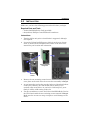
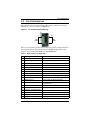
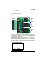
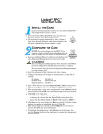
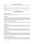
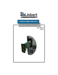
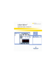
Infrastructure Management & Monitoring
For Business-Critical Continuity™
Liebert® IntelliSlot® Relay Card
User Manual
TABLE OF CONTENTS
1.0
INTRODUCTION . . . . . . . . . . . . . . . . . . . . . . . . . . . . . . . 1
Inspecting Shipment on Receipt . . . . . . . . . . . . . . . . . . . . . . . . 1
2.0
INSTALLATION . . . . . . . . . . . . . . . . . . . . . . . . . . . . . . . 2
Required Parts and Tools . . . . . . . . . . . . . . . . . . . . . . . . . . . . . 2
Instructions . . . . . . . . . . . . . . . . . . . . . . . . . . . . . . . . . . . . . . . . 2
3.0
PIN CONFIGURATION . . . . . . . . . . . . . . . . . . . . . . . . . . 4
4.0
JUMPER SETUP . . . . . . . . . . . . . . . . . . . . . . . . . . . . . . 5
Figures
Figure 1
Figure 2
Pin location and numbering . . . . . . . . . . . . . . . . . . . . . . . . . 4
Jumper location and numbering . . . . . . . . . . . . . . . . . . . . . 5
Tables
Table 1
Table 2
Relay card pin configuration . . . . . . . . . . . . . . . . . . . . . . . . 4
Jumper connections . . . . . . . . . . . . . . . . . . . . . . . . . . . . . . . 5
i
Introduction
1.0
INTRODUCTION
The Liebert IntelliSlot Relay Card (IS-RELAY) provides contact
closure for remote monitoring of alarm conditions in your Liebert unit.
The card is easy to install and integrates with other relay contact
monitoring systems.
This advanced power-management device is designed to function in
units with a Liebert IntelliSlot port. Some examples are:
• Liebert Nfinity™
• Liebert NX™
• Liebert UPStation GXT3™
Visit the Liebert Web site at www.liebert.com for the current list of
supported products.
On supported units, the inverter shut-off command can be controlled
from the computer directly connected to the UPS (via the factoryinstalled DB9 connector) and will conserve battery power after the
workstation shutdown is completed.
The Liebert IntelliSlot Relay Card is rated for 24VAC/VDC at 1A.
Inspecting Shipment on Receipt
Upon accepting shipment, inspect the packaging and product for any
damaged or missing parts. If any damage is observed, report it to the
shipping company and your local Emerson Network Power
representative. If any components are missing, contact your local
representative for replacement.
Items included with the shipment are:
• Liebert IntelliSlot Relay Card protected by an anti-static bag
• User manual
1
Installation
2.0
INSTALLATION
Make sure you have the following parts and tools before you begin.
Required Parts and Tools
• Liebert IntelliSlot Relay Card (provided)
• #2 (medium) Phillips or small flathead screwdriver
Instructions
1. Turning off the unit prior to installation is suggested, although
not required.
2. Locate the Liebert IntelliSlot port, which is on the rear of some
units, as shown in the examples below. Refer to the unit’s user
manual for port location and orientation.
Liebert IntelliSlot
Relay Card
Remove
screws
3. Remove the two retaining screws from the Liebert IntelliSlot port
cover plate on the unit. Save the screws for reassembly in Step 5.
4. As you insert the card, make sure the holes are aligned with those
on the UPS. Initially, the card should slide in freely as you
carefully align screw holes. As you feel it click into place, press
firmly to ensure solid seating in the slot.
5. Use the screwdriver to secure the Liebert IntelliSlot Relay Card to
the UPS chassis with the two retaining screws removed in Step 3.
Make sure the screws are snug, not tight, to avoid damage to the
device.
2
Installation
6. Use these guidelines for terminal block specifications:
Acceptable Wire Size
Wire Strip Length
24-16 AWG
0.24-0.28 in. (6-7mm)
Proceed to the following sections:
• 3.0 - Pin Configuration to configure the terminal blocks.
• 4.0 - Jumper Setup to configure the jumpers.
3
Pin Configuration
3.0
PIN CONFIGURATION
The card has two terminals blocks, TB1 (green, numbered 1-9) and
TB2 (black, 10-18), as shown in Figure 1.
Figure 1
Pin location and numbering
1
10
TB2
black
TB1
green
9
18
Refer to your Liebert product user manual for the pin configuration for
the terminal blocks. The pin functions in Table 1 apply only to the
Liebert units listed in Section 1.0 - Introduction.
Table 1 Relay card pin configuration
Pin
Function
Operation
1
Common - Low Battery
2
Low Battery
Closed if Low Battery point occurs.
3
Low Battery
Closed if battery is OK
4
Common - UPS Fault
5
UPS Fault
Closed if UPS fault occurs
6
UPS Fault
Closed if no UPS failure
7
Common - On Battery
8
On Battery
Closed if On Battery power (Utility failure)
9
On Battery
Closed if not On Battery power (Utility OK)
10 Signal Ground
Use for UPS Any-Mode Shutdown
11 Signal Ground
Use for UPS Any-Mode Shutdown
12 UPS Any-Mode Shutdown
Turn UPS output Off when shorted
to Pin 10 or 11
13 Summary Alarm*
Closed if no alarm conditions are present
14 Summary Alarm*
Closed if Summary Alarm occurs
15 Common - Summary Alarm*
16 On UPS
Closed if On UPS (inverter) power
17 On Bypass
Closed if On Bypass
18 Common - On Bypass
4
Jumper Setup
4.0
JUMPER SETUP
The card has five jumpers, P3 through P7, as shown in Figure 2.
Each jumper connects two pins.
Figure 2
Jumper location and numbering
FRONT OF
CARD
Jumper
P6
Jumper
P5
Jumper
P4
Jumper
P3
Jumper
P7
By default all five jumpers have shunts installed. The two pins are
shunted together to provide the functions shown in Table 2, allowing
relay commons to be tied together.
NOTE: The jumpers should be removed if there is any external voltage source that may intentionally or inadvertently be connected to the
relay.
Removing the shunt from any two pins breaks the connection between
the relay commons so they are not tied together.
Table 2
Jumper connections
Jumper
Relay
P6
On Battery
P5
UPS Fault
P4
Low Battery
P3
On Bypass
P7
Summary Alarm
5
Ensuring The High Availability
Of Mission-Critical Data And Applications.
Technical Support / Service
Web Site
www.liebert.com
Monitoring
[email protected]
800-222-5877
Outside North America: +00800 1155 4499
Single-Phase UPS & Server Cabinets
[email protected]
800-222-5877
Outside North America: +00800 1155 4499
Three-Phase UPS & Power Systems
800-543-2378
Outside North America: 614-841-6598
Environmental Systems
800-543-2778
Outside the United States: 614-888-0246
Locations
United States
1050 Dearborn Drive
P.O. Box 29186
Columbus, OH 43229
Europe
Via Leonardo Da Vinci 8
Zona Industriale Tognana
35028 Piove Di Sacco (PD) Italy
+39 049 9719 111
Fax: +39 049 5841 257
Asia
29/F, The Orient Square Building
F. Ortigas Jr. Road, Ortigas Center
Pasig City 1605
Philippines
+63 2 687 6615
Fax: +63 2 730 9572
While every precaution has been taken to ensure the accuracy and completeness of this literature, Liebert Corporation assumes
no responsibility and disclaims all liability for damages resulting from use of this information or for any errors or omissions.
© 2010 Liebert Corporation
All rights reserved throughout the world. Specifications subject to change without notice.
® Liebert is the registered trademark of Liebert Corporation.
All names referred to are trademarks or registered trademarks of their respective owners.
SL-23211_REV0_09-10
Emerson Network Power.
The global leader in enabling Business-Critical Continuity™
EmersonNetworkPower.com
AC Power
Outside Plant
Connectivity
Power Switching & Controls
DC Power
Precision Cooling
Embedded Computing
Racks & Integrated Cabinets
Embedded Power
Services
Infrastructure Management & Monitoring
Surge Protection
Emerson, Business-Critical Continuity, Emerson Network Power and the Emerson Network Power logo are
trademarks and service marks of Emerson Electric Co. or one of its affiliated companies.
©2010 Emerson Electric Co.