1
DIGITAL FAMILY OF SYSTEMS
Hardware and Configuration Manual
76-110-0685/F
Release SB6/DB6
Issue 1
110-0685/F
Release SB6/DB6
Issue1
DIGITAL
FAMILY OF SYSTEMS
Hardware Description Manual
Telrad Telecommunications Inc.
Woodbury, New York
110-0685/F
Release SB6/DB6
Issue 1
Telrad Telecommunications Inc.
Woodbury, New York
NOTICE
The information in this manual refers to the Telrad DIGITAL family of telephone systems, including the DIGITAL KEY BX system, Release SB6 and the DIGITAL 400 system, Release DB6, March, 1998. Telrad, Ltd., reserves the right to make changes in the equipment
described in this manual without notification. However, changes in the equipment do not necessarily render this manual invalid.
Additional copies of this manual may be obtained from Telrad, Ltd. Reproduction of this manual or parts thereof, without written permission from Telrad, Ltd., is strictly prohibited.
© 1998 Telrad Telecommunications Inc.
Woodbury, New York
The following are registered trademarks of the respective listed firms:
Trademark
Firm
Trademark
ACD I.Q.
Telrad Telecommunications, Inc.
Renata
AT&T
American Telephone and Telegraph Corp. StarSet
Hayes
Hayes Microcomputer Products, Inc.
SuperConsole
IBM
International Business Machines Corp.
Supra
IMAGEN
Telrad Telecommunications, Inc.
Telemagic
MS-DOS
Microsoft Corp.
TelradLINK
MS WINDOWS
Microsoft Corp.
UL
Telrad Tracker Set
Telrad Communications, Inc
Profile III
GN Netcom
Firm
Renata
Plantronics Corp.
Software Systems, Inc.
Plantronics Corp.
Remote Control International
Telrad Telecommunications, Inc.
Underwiters Laboratories, Inc.
FCC Regulations
Warning
This equipment generates, uses and can radiate radio frequency energy and if not installed and used in accordance with the instruction
manual, may cause interference to radio communications. Operation of this equipment in a residential area is likely to cause harmful
interference, in which case the user should contact the Telrad Field Service Department, at the telephone number listed below, to correct the interference problem. It has been tested and found to comply with the limits for a Class A computing device pursuant to Subpart
J of Part 15 of the FCC Rules which are designed to provide reasonable protection against such interference when operated in a commercial environment.
Registration
The Telrad DIGITAL Family systems are registered with the FCC based upon compliance with part 68 of its rules. Connection of these
systems to the nationwide telecommunications network is made through a standard network interface jack which you can order from
your telephone company. Jacks for this type of customer-provided equipment will not be provided on party lines or coin lines.
Hearing Aid Compatibility
DIGITAL family telephones are Hearing Aid compatible, as defined in Section 68.316 of Part 68 FCC Rules.
Telephone Company Registration
It is usually not necessary to call the telephone company with information on the equipment before connecting the DIGITAL family
system cabinet to the telephone network. But, if the telephone company should require this information, provide the following:
FCC Registration Number
- Key system
ARAISR-18430-KF-E
(on label affixed to cabinet)
- Multi-function (Hybrid Key/PBX) systemARAISR-18427-MF-E
Ringer Equivalence Number
3.9B
USOC Jack:
DB15, RJ2EX, RJ2FX, RJSGX, RJ2HX, RJ21X, RJ48C
Service Order Code (SOC)
- for off premise extensions and all analog trunk cards except the DID card
9.OF
- for DID cards
AS.2
- for digital trunks
6.0P
Facility Interface Code (FIC): - Central Office Ground-start trunk
02GS2
- Central Office Loop-start trunk
02LS2
- Direct Inward Dialing
02RV2-T
- Off-premises extension
OL13C
- Primary Rate Interface (PRI24)
04DU9-1SN
- T1 (DIGITAL TRUNK) 04DU9-BN, 04DU9-DN. 04-DU9-1KN, 04DU9-1SN, 04-DU9-1ZN
- E&M (TIE TRUNK INTERFACE -- 2-wire)
- E&M (TIE TRUNK INTERFACE -- 4-wire)
Rights of the Telephone Company
If the system is determined to be causing harm to the telephone network, the telephone company may discontinue your service temporarily. If possible, the telephone company will notify you as soon as possible. You will be given the opportunity to correct the situation
and you will be informed of your right to file a complaint to the FCC. Your telephone company may make changes in its facilities, equipment, operations, or procedures that could affect the proper functioning of your system. If it does this, you will be notified in advance
to give you the opportunity to maintain uninterrupted telephone service.
In the event of an equipment malfunction, all repairs will be performed by Telrad Telecommunications, Inc., or by one of its authorized
dealers.
Address of repair facility in USA
Telrad Service Center, 135 Crossways Park Drive, Woodbury, NY 11797. Phone: 1-516-921-8300 or 1-800-645-1350.
THIS PAGE INTENTIONALLY LEFT BLANK
Section 1
INTRODUCTION
1. 1
GENERAL
This section provides introductory information about the
manual and a general overview of the DIGITAL family of
telephone systems. These systems, the DIGITAL KEY BX (a
128 port system) and the DIGITAL 400 (a 384 port system),
are also referred to as ''DIGITAL systems''.
1. 2
SCOPE OF MANUAL
1. 2. 1 Purpose
This manual serves as a reference for the DIGITAL systems.
It provides a functional and physical description of its
equipment.
The manual is intended for DIGITAL system customers and
distributors, as well as for personnel involved in DIGITAL
system installation, servicing, and customer training.
1. 2. 2 Contents
Section 1
Includes a general explanation of the
contents of the manual and information on
applicable documents.
Section 2
Provides a functional description of the
systems and describes the systems’
installation, administration and
maintenance.
1-1
76-110-0685/F, Issue 1
1. 3
Section 3
Describes common system equipment
including the MPD card, Main Motherboard
and Small Auxiliary Motherboard (SAX).
Section 4
Describes the peripheral cards used in the
systems.
Section 5
Details the power supply requirements,
including external connectors and switches.
Section 6
Includes description of the proprietary
telephone sets and the terminal equipment
option cards.
Section 7
Details system wiring, including the MDF
connection, and printer, PC, and external
modem connections.
Section 8
Describes the configuration of the telephone
sets.
Section 9
Includes functional description of external
equipment and hardware requirements.
Appendix A
Details system provisioning.
Appendix B
Details system specifications.
SYSTEM DEFINITION
1. 3. 1 DIGITAL KEY BX system
The DIGITAL KEY BX is a highly flexible, digital, integrated
voice/data business telecommunications system providing
up to 128 ports with a maximum of 48 outside lines (with up
to 80 extensions) or 96 extensions (with up to 32 outside
lines). In addition, the system accommodates up to eight 36button Add-on units.
1. 3. 2 DIGITAL 400 system
The DIGITAL 400 is a highly flexible, digital, integrated voice/
data business telecommunications system providing up to
384 ports with a maximum of 144 outside lines (with up to
240 extensions) or 254 extensions (with up to 130 outside
lines). Its many features can be tailored to your exact
specifications and can be modified at any time to match your
organization's changing needs.
1. 3. 3 System features
The DIGITAL systems can be installed in any office. They are
quiet, operate under normal office environmental conditions
and can be located almost anywhere within the customer's
premises.
1-2
Section 1: INTRODUCTION
The DIGITAL systems feature:
• Automatic Call Distribution (ACD, and ACD I.Q. options;
• Ability to connect Single Line Telephones (SLTs) and
compatible equipment;
• Handsfree answerback speakerphone enabling offhook
voice announce option;
• Modular and flexible design;
• Multisystem networking capability;
• Optional programming of extensions to utilize the Multiple
Station Appearance (MSA) approach;
• Port oriented architecture;
• PRI24/PRI30 and BRI digital Integrated Services Digital
Network (ISDN) outside line compatibility;
• System cabinet cards (except the MPD card) common to
both systems;
• System expansion using additional cabinets;
• T1/E1 digital outside line compatibility
1. 3. 4 Technology
DIGITAL systems combine the ease of use of a key system
with the sophistication of a Private Branch Exchange (PBX).
The DIGITAL systems make full use of advanced technology
including:
•
•
•
•
•
•
•
•
•
Computer Telephone Integration, including Circuit
switched data (CSD), Circuit switched voice (CSV),
Telephony Application Programming Interface (TAPI);
Telephony Services Application Programming Interface
(TSAPI);
Digital communications and signaling;
Distributed control using microprocessors located in both
the proprietary telephone sets and in each system card;
Electronic component miniaturization by use of Surface
Mount Technology (SMT);
End-to-end digital, including digital telephone sets;
Integrated voice and data using an S bus, with 2B+D
architecture, to enable connection of two proprietary
telephone sets on one line;
Voice activated dialing.
1. 3. 5 External devices
The following industry-standard, external devices can be
connected to the DIGITAL systems:
•
•
•
•
•
Announcers;
Answering machines;
Background music source;
Bells;
Cordless/wireless telephones;
1-3
76-110-0685/F, Issue 1
•
•
•
•
•
•
•
•
•
•
•
•
1. 4
Door locking and opening units;
Equipment activating relays, sensors and switches;
Fax machines;
Headsets;
ISDN modems;
Modems;
Music on hold source;
Paging devices;
Personal computers;
Printers;
Video conferencing devices;
Voice mail systems.
APPLICABLE DOCUMENTATION
This manual is one of a series on the DIGITAL systems,
including the following documents. Except where specifically
identified as being applicable to either the DIGITAL KEY BX
system or the DIGITAL 400 system, the documents listed
below are applicable to both.
System manuals
ACD documentation
1-4
Document
Catalog Number
Feature Description manual
Provides a description of the DIGITAL
system’s features, and details the
criteria for its configuration.
76-110-0690/F
Operating instructions
Details the operation of the many
system and user features.
Administration manual
Contains a detailed explanation of the
programmable features and
parameters and a guide to the
programming of each of them on a
personal computer.
76-110-0165/F
Administration forms
Contains a copy of each of the
programming forms.
76-110-0405/F
Installation manual
Contains a detailed explanation of the
hardware installation and functional
verifications.
76-110-0410/F
Maintenance manual
Contains a detailed testing and
maintenance guide.
76-110-0170/E
ACD agent user guide
76-110-0425/D
ACD system manual
76-110-0430/D
76-110-0175/F
Section 1: INTRODUCTION
Data options
Option
documentation
System user
documentation
Telrad Tracker Set
Package
documentation
Technical addenda
ACD I.Q. user manual
76-110-0675/F
ACD supervisor user guide
ACD I.Q. Wallboard Installation and
Programming guide
TAPI/TelradLINK Installation and
Programming Manual
Universal data card manual
76-110-0440/D
Electronic Business Card
Installation and Programming
manual (with IMAGEN only)
Executive set with expanded display
user guide
76-110-0380/F
Executive set and Executive set with
display user guide
79-100-0006/F
Speakerphone set and Display
Speakerphone set user guide
79-500-0006/F
4 Button set and 16 Button set user
guide
79-400-0006/F
Single Line Telephone user guide
Analog telephone set user guide
76-110-1706/F
Attendant console user guide
79-120-0006/F
Executive set with expanded display
quick reference guide
79-100-0021/F
Executive set and Executive set with
display quick reference guide
79-100-0020/F
Speakerphone set and Display
Speakerphone set quick reference
guide
79-500-0009/F
4 Button set and 16 Button set quick
reference guide
79-400-0009/F
Single Line Telephone quick
reference guide
79-110-0007/F
User Guide
79-070-0009/6
Quick Reference Guide
79-070-0008/2
Configuration Addendum
79-070-0007/9
Data card installation for Executive
stations
79-020-0306/D
Data card installation for standard
stations
76-020-0406/D
Option module installation
76-110-0545/D
Upgrade manual
76-110-0455/F
76-110-0585/F
79-123-0410/E
79-125-0410/F
79-100-0009/F
73-510-3000/F
1-5
76-110-0685/F, Issue 1
IMAGEN
1. 5
IMAGEN Integrated Voice Mail
Application Generator User manual
76-110-0570/H
IMAGEN Integrated multiapplication generator System
manual
83-130-8050/I
Integrated SMDR Call accounting
manual
83-110-0270/H
IMAGEN Executive set with
expanded display user guide
76-110-0190/H
IMAGEN digital telephone set,
analog telephone set and SLT user
guide
76-110-0205/H
IMAGEN quick reference guide
76-110-0620/H
THE CURRENT ISSUE
This issue, SB6/DB6, replaces the previous issue, SB5/DB5.
The System Description of the previous issueincluded both
Hardware and Feature Descriptions. In this release,
Hardware and Features are discussed in separate
documents.
All release revisions and enhancements apply to both the
DIGITAL KEY BX system and the DIGITAL 400 system,
where not specified otherwise.
Differences between the various aspects of the two systems,
where applicable, are discussed in the pertinent sections of
this manual. Where no differences are mentioned, assume
that there are none.
1. 6
CONVENTIONS
1. 6. 1 Terminology conventions and abbreviations
This manual refers to both the DIGITAL KEY BX and
DIGITAL 400 systems. These two systems are referred to in
this manual as the DIGITAL systems or the DIGITAL family
of systems depending on the context.
The DIGITAL family of systems supports three types of
telephones:
•
1-6
Telrad digital telephones:
Referred to in this manual as digital telephone sets or
DIGITAL telephone sets;
Section 1: INTRODUCTION
•
Telrad analog key electronic telephones:
Referred to in this manual as analog key telephone sets;
•
Single line analog telephones:
Referred to in this manual as single line telephones or
SLTs.
Depending on the type and size of your DIGITAL system,
one of the following MPD cards is used:
•
MPD386
This is the name of the MPD card used with all DIGITAL
KEY BX (128 port) systems. This MPD card can also be
used with one-cabinet DIGITAL 400 systems (up to 128
ports).
•
MPD S400
This is the name printed on the MPD card used with all
DIGITAL 400 systems. This MPD card must be used with
any DIGITAL 400 system having more than 128 ports and
with all multiple cabinet DIGITAL 400 systems.
The following abbreviations are used in this manual:
•
•
•
•
•
•
ACD
ACD I.Q.
AWG
BBU
BERT
BRS
•
BRT
•
BHT
•
•
•
CHL
CO
COG
•
•
•
•
•
•
•
•
•
•
•
•
•
•
COL
CSU
CSV
DCD
DID
DIP
DTE
EHD
EHU
ELA
ELD
EMD
EMI
FRRN
Automatic Call Distribution;
Automatic Call Distribution Information Query;
American Wire Gauge;
Battery Backup Unit;
Bit Error Rate;
ISDN Basic Rate Interface internal line card
(station);
ISDN Basic Rate Interface internal line card
(four ports)
ISDN Basic Rate Interface internal line card
(two ports);
Analog loop-start outside line card (four ports);
Central Office (public exchange);
Analog ground-start outside line card (eight
port);
Analog loop-start outside line card (eight port);
Channel Service Unit;
Circuit Switched Voice;
Data Carrier Detector;
Direct Inward Dialing;
Dual In-line Package;
Data Terminal Equipment;
Digital telephone set card with four ports;
Error Handling Unit;
Analog telephone set card with eight ports;
Digital telephone set card with eight ports;
E and M tie card (networking);
Electromagnetic Interference;
Free running;
1-7
76-110-0685/F, Issue 1
•
•
•
•
•
•
•
•
•
•
•
•
•
•
•
•
•
•
HONS
IMAGEN
ISDN
LED
MDF
MFC
MPD
OCD
ONS
OPX
PCM-30
PRI
PRIM
RFI
SAX
SEC
SHD
SLD
•
•
SLT
T1
Eight port card for on-site SLTs
Integrated Multi-Application Generator;
Integrated Services Digital Network;
Light Emitting Diode;
Main Distribution Frame
Multifreqency Compeller;
Main Processing card;
Option card;
16 port card for on-site SLTs;
Off Premise Extension;
30 channel E1 digital outside line card;
ISDN Primary Rate Interface outside line card;
Primary;
Radio Frequency Interference;
Small Auxiliary motherboard;
Secondary;
Four port SLT card with OPX capabilities;
Eight port SLT card with OPX and message
lamp capabilities;
Single Line Telephone;
24 channel digital outside line card.
1. 6. 2 Assumptions
It is assumed that those using this manual have a basic
knowledge of telephony, the use of a personal computer and
the Telrad DIGITAL telephone systems.
1-8
Section 2
GENERAL DESCRIPTION
2. 1
GENERAL
This section contains the functional description of the
system, as well as a brief explanation of the system’s
installation, administration, and maintenance.
2. 2
FUNCTIONAL DESCRIPTION
2. 2. 1 Control
The System control functions are located on the MPD card.
The MPD's Central Processing Unit (CPU), a 16 bit
microprocessor, is responsible for the calculations and any
decision making involved in call processing. The CPU is also
responsible for the statistical allocation of communication
channels (See Figure 3-3).
The MPD uses the internal LAN, located on the
motherboard, for signal transmission. Control signals are
transmitted to other system cards, using packet switching at
1.5 megabits per second, according to the CSMA/CD
protocol.
Each system card, including the MPD, contains a16 bit
microcontroller which controls the hardware components on
the card and handles communications.
2-1
76-110-0685/F, Issue 1
2. 2. 2 Signaling
Data communication between terminal equipment and the
system cabinet is carried out on the D channel of the S bus.
This provides a channel for signaling, dialing, etc., operating
at 16 Kb per second. The CSMA/CD packet switching
protocol is used.
2. 2. 3 Call switching
Call switching is carried out by the switching matrix, located
on the MPD card. The switching matrix is controlled by the
card's CPU and determines the time slots used to switch
between the system’s PCM highways. There are eight PCM
highways in the DIGITAL KEY BX and 16 PCM highways in
the DIGITAL 400. Each PCM highway has 32 time slots, one
for tones, and the others for speech. Calls are routed on the
B channels of the S bus at 64Kb per second. Depending on
the customer's requirements, either the µ-law PCM method
(North American standard) or the A-law method (European
standard) of analog-digital conversion is used. The system is
non-blocking, i.e., all outside lines and extensions can be
used simultaneously.
2. 2. 4 Call processing
All decisions regarding call processing are carried out by the
MPD's CPU. The CPU accepts input from other cards and
terminal equipment and makes output decisions based on
the following:
•
Static databases that reflect the system configuration as
defined in system administration (refer to the DIGITAL
systems Administration manual);
•
Dynamic databases that reflect the immediate status of
the system as reported by both peripheral cards and terminal equipment.
The CPU’s decisions result in signal outputs to the peripheral
cards, the dynamic database, the switching matrix and any
auxiliary resources (DTMF receivers, tone generators, etc.)
with which the system is provisioned.
2. 3
INSTALLATION
The installation of a DIGITAL system comprises several
stages: planning, site preparation, physical installation and
system verification.
2-2
Section 2: GENERAL DESCRIPTION
The system includes up to three modular cabinets,
connected by cables. Each cabinet includes its own power
supply and slots for DIGITAL printed circuit cards. A basic
description of the system cabinet for each of the DIGITAL
systems is presented in Section 3. 2.
A single, 25-pair, cable connects each card to the Main
Distribution Frame (MDF). Two- or three-pair crossconnect
or two-pair covered wire (24 AWG) cables, or three-pair
crossconnect or three-pair covered wire for analog sets,
connect the MDF to junction boxes. The ISDN passive bus
enables two telephone sets to be connected to one port on
each ELD or EHD card. Outside lines from the Central Office
are wired directly to the MDF.
For ease of identification, each hardware item, such as the
cabinets, option modules, etc., comes in its own container
together with an explanatory note detailing installation
procedures.
The considerations for planning the location of the cabinets
and telephone sets and comprehensive installation
instructions and procedures are detailed in the DIGITAL
Installation manual.
2. 4
ADMINISTRATION
DIGITAL systems are configured by means of a personal
computer (IBM PC, 286, 386, 486 Pentium or compatible)
with a hard disk. The software is installed onto the computer
using a proprietary installation program. The configuration
program is menu-driven, user friendly and self-explanatory.
The DIGITAL systems are configured in three stages:
•
•
•
The configuration is planned on administration forms;
This data is entered into the configuration computer;
The configuration data is restored (downloaded) to the
DIGITAL system.
The configuration program operates in one of two modes offline and online:
•
•
In offline mode, there is no connection between the PC
and the DIGITAL system. A customer configuration file is
prepared and stored on disk. This file is transferred to the
system at a later time.
In the online mode, the PC is connected directly to the
system, either via modem, or locally via a cable
connected to the MPD card. A new configuration can be
2-3
76-110-0685/F, Issue 1
restored to the system, and the current configuration can
be backed up (uploaded) to the PC, for backup or
modification. As soon as a restore is complete, the new
configuration is operational. This makes updating and
modifying an existing configuration both simple and time
saving. No visit to the customer site is necessary.
Most of these procedures are performed without interruption
to system operation.
Comprehensive administration instructions and procedures
are included in the DIGITAL Administration manual. A
separate Administration Forms manual includes all the
programming forms.
2. 5
MAINTENANCE
2. 5. 1 General
Corrective maintenance consists of fault detection, isolation
and bad or faulty unit replacement. No preventative
maintenance is required.
Basic instruction in system maintenance is provided within a
very short time. Comprehensive maintenance information is
contained in the DIGITAL Maintenance manual.
2. 5. 2 Fault detection
Fault detection equipment is built in. Upon detection of a
fault, the system generates a warning which is defined either
as a major alarm, a minor alarm or a diagnostic alarm,
depending on the severity of the fault. All alarms and
messages are stored in the system Error Handling Unit
(EHU). These messages are examined and evaluated later
by maintenance personnel.
The warnings can be sent at a later time to the printer used
for Station Message Detail Recording, or to a computer
connected to the system. In addition, major and minor alarms
are displayed at the attendant console.
The system also generates diagnostic messages which
provide information on the system's status. The alarm
message alone often provides the necessary information to
isolate the faulty unit.
2-4
Section 2: GENERAL DESCRIPTION
If a fault liable to disrupt system operation is detected, the
system can dial the Service Center automatically via an
external modem and transmit the most recently generated
alarms. This occurs when in remote modem mode.
By utilizing the maintenance information feature, you can
display a series of current data on the Administration PC.
This includes information regarding each port on each card
of each shelf in the system cabinet, including its in-service or
out-of-service status.
2. 5. 3 LEDs
A further aid to maintenance is provided by LED indicators on
various system cards. For example, indicators are located on
Central Office COG, COL and CHL outside line cards for
each outside line circuit. The LEDs indicate whether circuits
on the card are operating correctly.
2. 5. 4 Maintenance testing
In the DIGITAL 400 system only, a series of three
maintenance testing and information approaches are used.
These allow for flexibility in planning and carrying out
comprehensive surveillance and review of the status and
operation of the system and its various components. These
approaches can be used individually or in combination to suit
system needs. They include the following:
Online component testing A specific component or
system resource to be tested can be selected from the
appropriate menu. The test results are displayed
immediately on the screen of the administration PC.
Examples of tests on system cards are channel loop-back
tests on line cards and outside line cards and local loop-back
and remote loop-back tests on T1/E1 cards. An example of
system resource testing is a DTMF receiver test.
Utilizing a softkey on the Administration PC, individual ports
currently in service can be taken out of service, and ports that
have been declared out of service can be put back into
service.
Daily administration testing Daily system testing,
including a range of elements defined in the configuration
program, can be scheduled for output at a fixed hour each
day. Daily automatic testing can be used to check all system
ports and detect defective units out of service. A variety of
other test data can be derived from daily test reports,
including the following:
2-5
76-110-0685/F, Issue 1
•
•
•
•
•
channel loop-back failures;
outside line test failures;
outside line status;
DTMF receiver failures;
DTMF receiver status.
Maintenance information The Maintenance information
utility can be used to review operational status and
parameters of each card in the system, as well as each of
that card's components. A detailed list provided for a card
includes the following:
•
•
•
•
•
the DN for each line;
outside line or module port;
the port number and type;
the corresponding highway, time slot, bus and terminal
number (where applicable);
in service or out of service status.
2. 5. 5 Technician set
An Executive set with expanded display with a data card can
be utilized by authorized personnel as a Technician set.
When suitably activated, the Technician set can simulate any
type of telephone set in the system, in any configuration type.
The set is a vital tool either in installation, debugging or
revision of set and configuration assignments.
2. 5. 6 System reset
Many maintenance functions, such as system reset, can be
initiated from a remote location so the fault can be corrected
without a technician visiting the customer site.
Two types of system resets are available from the PC:
•
•
Programmer reset -- resets the entire system while
maintaining the present configuration;
Default reset -- resets the entire system, by performing
default download, while reverting to the default configuration.
The default reset can also be initiated manually using the
MPD card reset buttons.
2. 5. 7 Corrective action
Corrective action involves the replacement of the faulty
equipment (telephone set, card, power supply, etc.). In most
cases, this can be performed without disruption to system
operation.
2-6
Section 3
COMMON SYSTEM EQUIPMENT
3. 1
GENERAL
This section provides a brief functional description of the
system hardware components which are shared by all of the
users, including block diagrams of major units.
3. 2
SYSTEM CABINET
The system cabinets for each of theDIGITAL systems are
shown as follows:
•
•
Figure 3-1: for the DIGITAL KEY BX system;
Figure 3-2: for the DIGITAL 400 system.
3. 2. 1 DIGITAL KEY BX system
The system cabinet contains the power supply, the
motherboard and the system cards which fit into card slots in
the housing and connect to the motherboard.
The DIGITAL 400 system can consist of a maximum of three
cabinets. Each cabinet contains six card slots. The MPD
card must be placed in the:
•
•
first slot of the cabinet, in a single cabinet configuration;
first slot of the first cabinet, in a multicabinet
configuration.
All other card slots are universal, i.e., any card can be placed
in any slot.
3-1
76-110-0685/F, Issue 1
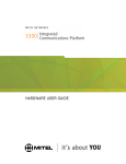
Figure 3-1 DIGITAL KEY BX system cabinet
3-2
Section 3: COMMON SYSTEM EQUIPMENT
3. 2. 2 DIGITAL 400 system
The system cabinet contains the power supply, the main
motherboard, the Small auxiliary motherboard (optional) in
one cabinet systems, and the system cards which fit into
slots in the housing and connect to the motherboard.
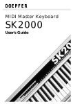
Figure 3-2 DIGITAL 400 system cabinet
The DIGITAL 400 system can consist of a maximum of three
cabinets. Each cabinet contains 15 card slots. The MPD card
must always be placed in the first slot from the left of the:
•
•
single cabinet -- in a one cabinet, configuration;
upper cabinet -- in a two cabinet configuration;
3-3
76-110-0685/F, Issue 1
•
middle cabinet -- in a three cabinet configuration.
All other slots are universal; any card can be placed in any
slot. An installation, using a single DIGITAL 400 system
cabinet, can be configured as a DIGITAL KEY BX system
with up to 128 ports.
3. 3
SYSTEM CABINET MOUNTING OPTIONS
3. 3. 1 The DIGITAL KEY BX system
The DIGITAL KEY BX cabinet is constructed for easy
mounting on a wall. The one cabinet configuration can be
mounted with either:
•
•
The rear panel against the wall;
One of the side panels against the wall.
Two or three cabinet configurations are mounted with the
cabinet rear panels against the wall. To rear mount either a
one, two or three cabinet system, the DIGITAL KEY BX wall
mounting kit is required.
3. 3. 2 The DIGITAL 400 system
The DIGITAL 400 cabinet is constructed for easy mounting,
in one of the following ways:
A single cabinet can be wall mounted, with the rear panel
against the wall, as shown on the right side of Figure 3-2,
above;
•
One cabinet, two cabinet or three cabinet configurations
can be stack mounted on a wheel assembly, as shown on
the left side of Figure 3-2 above.
For detailed mounting instructions, refer to theDIGITAL
family of systems Installation manual.
3. 4
LINKING SYSTEM CABINETS
3. 4. 1 The DIGITAL KEY BX system
Up to three system cabinets can be linked together, enabling
modular growth.
3-4
Section 3: COMMON SYSTEM EQUIPMENT
Only the first cabinet's power supply is connected to the
110 V input power. Each of the other cabinets' power supply
units draw their power from the adjacent cabinet. All but the
first power supply unit are permanently switched on.
The motherboards of each cabinet, in a multicabinet system,
are linked in series by means of flat cables which carry the
internal LAN and PCM highways.
3. 4. 2 The DIGITAL 400 system
Up to three system cabinets can be linked together enabling
modular growth. Although they appear to be externally
identical, the top and middle cabinets in two cabinet and
three cabinet systems have no bottom panel, to facilitate
required wiring, cabling, and air circulation.
Each cabinet's power supply is connected to the 110 V input
power:
•
•
•
via a cable, directly to a dedicated wall outlet, for a wall
mounted system;
via a cable from each cabinet's power supply, plugged
into an outlet mounted on the wheel assembly;
via a single cable from the wheel assembly composite
outlet to a dedicated wall outlet.
In a multicabinet system, the motherboards of the various
cabinets are linked in series by means of flat cables which
carry the internal LAN and PCM highways. An additional
small SAX is installed in the upper cabinet of a two cabinet
system, and in the middle cabinet of a three cabinet system.
The SAX is installed in the same cabinet in which the MPD
card for the respective system is inserted.
For more information, refer to the DIGITAL family of systems
Installation manual.
3. 5
MAIN PROCESSING (MPD) CARD
The MPD card is the system's main control unit. It supervises
and controls all the peripheral cards in the system and
provides all the system's signaling and switching capabilities.
The system software program and configuration data reside
in a plug-in memory cartridge.
Only one MPD card is used per system.
Two MPD card models are available, depending on the
system size:
3-5
76-110-0685/F, Issue 1
MPD386
• is used in all DIGITAL KEY BX systems;
• can be used in a DIGITAL 400 system configuration using
a single cabinet (containing up to 128 ports). If you
expand the configuration, this model has to be replaced.
• contains four analog Central Office Outside line (loop
start) interface ports, enabling the connection of up to four
outside lines. This allows very small installations to
operate without any outside line card.
• includes an auxiliary services unit, with a DTMF receiver
and two analog audio channels with general purpose
relays, which support such features as music on hold,
background music, door unit, and external page.
MPD-S400
• must be used in all DIGITAL 400 multicabinet system
configurations containing up to 384 ports;
• supports 384 ports, additional Multi-Directory Number
(MDN) groups, as well as other expanded capabilities.
3. 6
FUNCTIONAL UNITS
The MPD can be divided into the following functional units,
shown schematically in Figure 3-3:
•
•
•
•
•
•
•
•
•
•
•
•
Central processing unit (CPU);
Memory cartridge;
Microcontroller unit;
Switching matrix;
386 processor on the MPD386; 286 processor on the
MPD-S400 card
Communication interface;
Analog CO interface unit (on the MPD386 only);
Auxiliary unit;
Services unit;
RS-232C interfaces;
Mailbox;
Digital Phase Locked Loop (DPLL) synchronization unit
(on the MPD-S400 card only);
However, a DPLL synchronization daughterboard can be
mounted on the MPD386, for Digital Key BX systems that
have T1 or E1(PCM 30 or E1-MFC-R2), BRT, BHT, PRI24,
or PRI30 cards.
.
3-6
Section 3: COMMON SYSTEM EQUIPMENT
Figure 3-3 MPD card major subsystems
3. 6. 1 Central processing unit (CPU)
The central processing unit is based on a 16 bit
microprocessor. The CPU makes the calculations and
decisions involved in call processing, such as call switching
on the switching matrix. The CPU integrates and conducts
the system data processing.
The CPU's primary responsibilities are as follows:
•
•
•
•
•
Call switching via the switching matrix;
B-channel management;
Call signaling, e.g., data transfer between the cards and
the telephone sets in the system via the D-channel;
Implementation and data processing of the configuration
created using the configuration program;
System features implementation, e.g., (Least Call
Routing) LCR and hunt groups.
3-7
76-110-0685/F, Issue 1
3. 6. 2 Memory cartridges
Every MPD card requires a memory cartridge. There are four
types of memory cartridges available as shown in Table 3-1.
The type of memory cartridge that you need for your system
depends on the style of the MPD card and whether or not
your system supports Automatic Call Distribution (ACD).
Table 3-1 Memory cartridge models
MPD type
Memory cartridge
MPD386
Basic 128 port model ACD 128 port model
MPD-S400
Basic 384 port model ACD 384 port model
The MPD386 memory cartridge has up to 3 Mb of Flash
Read only memory (ROM) and up to 2 Mb of memory.
The MPD-S400 memory cartridge has up to 1.5 Mb of Flash
Read only memory (ROM) and up to 1.5 Mb of memory.
Both systems use Static Random Access Memory (SRAM)
for system configuration data. The memory cartridges also
include an internal "mailbox" which is used in communicating
with the rest of the system.
The memory cartridges have a replaceable lithium battery
with a three year average life expectancy. The plastic
memory cartridge is sealed, and has a sliding door for easy
access to the battery. See the Installation and Maintenance
manuals for details of the battery replacement procedure.
3. 6. 3 Microcontroller unit
The microcontroller, an eight bit Universal Communications
Controller (UCC), mediates between the CPU, the rest of the
MPD card's functional units and the rest of the system.
The UCC does the following:
•
•
•
•
•
•
3-8
Implements CPU decisions regarding call switching on
the switching matrix;
Controls the auxiliary unit;
Controls the service unit;
Mediates between the CPU and the Analog Central Office
unit (on the MPD386 only);
Channels information between the card's RS-232C
interface and the CPU;
Interprets CPU messages for other cards, or terminal
Section 3: COMMON SYSTEM EQUIPMENT
•
equipment, for dispatch via the communications unit;
Handles all communication requirements.
3. 6. 4 Switching matrix
The switching matrix handles all the system’s switching
requirements, under the control of the CPU. The matrix also
contains the conference call circuits. A control unit governs
the conference call circuits operation by switching the PCM
highways to connect to the conference circuit.
3. 6. 5 Communications interface
The primary purpose of the communication unit is to mediate
between the system outside the MPD card and the Control
unit, via the motherboard. Communication is by the internal
LAN, for signal transmission at 1.5 MB per second according
to a proprietary protocol. This protocol specifies
communication standards.
3. 6. 6 Analog Central Office (ACO) Interface unit
The MPD386 contains an Analog Central Office (ACO) unit
for connection of four loop start outside lines from a CO. The
unit is identical in function to the COL card, but can handle
only four outside lines.
The ACO unit is controlled by the Peripheral Board Controller
(PBC) of the communications unit.
3. 6. 7 Auxiliary unit
The Auxiliary unit contains the following system internal
utilities:
•
•
•
•
Real time clock (RTC). This provides the time displays on
the DIGITAL system telephone sets;
Pulse Coded Modulation (PCM) clock. This provides the
clock and synchronous impulses for the system and
mediates between the system and the CO;
PCM call progress tone generator. This generates
ringback tone, dial tone, busy tone, reorder (error) tone,
etc. These tones are sent to the telephone sets through
the tone highway;
Duel Tone Multi-Frequency (DTMF) generator. This
creates 16 tones for DTMF dialing on outside lines.
3-9
76-110-0685/F, Issue 1
3. 6. 8 Services unit
The following resources are provided by the auxiliary
services unit:
•
On the MPD386;
− One, half duplex, audio channel which can be used for
Background Music (BGM) and music on hold (MOH)
in one direction and external page in another.
− An external music on hold (MOH) and Background
Music (BGM) source can be connected via the RCA
jack provided;.
− One relay (electromechanical switch) is used for door
unit operation, external bells etc. It can activate a
different external page zone.
− One relay. Each relay can activate a different external page zone.
− A DTMF receiver.
•
On the MPD-S400 card
− One audio channel can be used for BGM.
− One audio channel can be used for MOH. An internal
MOH chip provides ten melodies, played serially for
MOH, or an external MOH source can be connected
− A DTMF receiver.
3. 6. 9 Jumpers (On the MPD386)
Ground definition jumper An RS-232 ground definition
jumper is located on the MPD386 (as on all CO cards and
OCD cards). The jumper, set by the technician in the field,
determines whether an attached device will be signal ground
("natural state") or frame ground. This is important in
reducing electromagnetic interference "noise".
3. 6. 10 Digital Phase Locked Loop (DPLL) synchronization unit
The DPLL synchronization unit consists of the DPLL Frame
Reference switch. This connects the reference signal and
the DPLL Clock generator. The clock generator ensures that
the data is transmitted in a synchronized manner from the
DPLL reference clock on the MPD card. The time base of the
generator is a crystal oscillator with an accuracy rate of
between 10-5 and 10-6, according to the Stratum 4 standard.
When the system is connected to a Central Office, the
system clock, controlled by the timing unit, is synchronized
with an external clock in the Central Office.
This unit is an integral part of the model MPD-S400 card.
However, a special DPLL daughterboard cartridge must be
connected to the MPD386, if used in a configuration with a
T1, E1 (PCM 30 OR E1-MFC-R2), BRT, BHT, PRI24 or
PRI30 card.
3-10
Section 3: COMMON SYSTEM EQUIPMENT
3. 7
MPD CARD EXTERNAL CONNECTIONS
A label strip gives the names of the external connectors and
buttons. It appears on the first system cabinet, next to the
MPD card. (See Figure 3-4.)
A 50-pin connector connects the MPD386 to the MDF. A
single 64-pin connector connects the MPD386 to the
motherboard.
Two 64-pin connectors connect the model MPD-S400 to the
motherboard.
A Music On Hold RCA jack is provided for connection of an
external MOH source.
A Background Music RCA jack is provided for connection of
an external BGM source.
Figure 3-4 MPD card external connections
There is an RS-232C port on both the MPD386 and MPDS400. This allows connection to either a personal computer
for system administration and maintenance, a terminal, an
external modem or a printer.
One additional RS-232C port is provided for future use on the
Model MPD386. Two additional RS-232C ports are provided
for future use on the Model MPD-S400.
3-11
76-110-0685/F, Issue 1
3. 8
MAIN MOTHERBOARD
The motherboard is fixed permanently at the rear of the
cabinet and provides all the connections required among the
power supply, system cards, and other motherboards in
multicabinet configurations. The motherboard has a 64 pin
male connector for each of the system cards as follows:
•
•
six cards for DIGITAL KEY BX;
15 cards forDIGITAL 400.
You can use flat cable connectors to link the motherboard to
other motherboards located in adjoining cabinets.
In the DIGITAL KEY BX system cabinet, a cable terminating
in a 12-pin female connector connects the motherboard to
the power supply.
In the DIGITAL 400 system cabinet, the power supply is
inserted into the system cabinet. A connector on the rear of
the power supply plugs into its counterpart connector on the
main motherboard.
The motherboard provides channels for the following:
•
•
•
•
3. 9
Supply voltages, connected in parallel to all cards;
Signaling and data on the internal global serial
communication LAN ("G"-bus). The "G"-bus functions
both as a PCM highway and as the LAN between the
cards;
Eight PCM highways for DIGITAL KEY BX and eight PCM
highways forDIGITAL 400. Each highway is connected to
all the respective card connectors;
Clock impulses, of 8 KHz and 4 MHz.
SMALL AUXILIARY MOTHERBOARD (SAX)
An additional small auxiliary motherboard must be installed
in multicabinet DIGITAL 400 systems only.
The SAX can be installed as follows:
•
•
•
3-12
in the upper cabinet of a two cabinetDIGITAL 400 system;
in the middle cabinet of a three cabinet DIGITAL 400
system (the same cabinet in which the MPD card for the
respective system is inserted);
the lower cabinet of a multicabinetDIGITAL 400 system.
Section 3: COMMON SYSTEM EQUIPMENT
The installation of a SAX allows intercabinet access to
additional highways. It enables placement of cards with two
back connectors to the motherboard in the first three card
slots of the middle system cabinet in which the SAX is
installed. When possible, place T1 (Style D0 or higher only)
E1 (PCM 30 or E1-MFC-R2 ), PRI24, PRI30, ONS, and
HONS cards in slots 2 and 3 of this system cabinet.
A SAX can also be installed in the lower cabinet of a
multicabinet DIGITAL 400 system, to provide access from
the first three card slots of the lower system cabinet to eight
additional highways. In this case, placeT1 (Style D0 or higher
only), E1(PCM 30 or E1-MFC-R2), PRI24, PRI30, ONS, and
HONS cards in slots 1, 2 and 3 of this system cabinet.
A standard one-cabinet configuration provides up to 128
ports and does not include a SAX motherboard. However,
you can order a non-standard configuration containing a
SAX motherboard. The addition of a SAX motherboard adds
outside lines to the system, enabling a one-cabinet system to
support the following:
•
•
•
174 ports where a PRI card is used;
176 ports where a T1 card is used;
188 ports where an E1(PCM 30 or E1-MFC-R2) card is
used.
The use of a two-cabinet system with two SAX motherboards
adds digital outside line ports to the system. This supports
336 ports when using digital outside line interfaces, such as
PRI24, PRI30, T1 or E1 (PCM 30 or E1-MFC-R2).
NOTE
The upper cabinet, supplied as an
Extended Cabinet Package, always
includes a SAX. However, configuring the
SAX in the upper cabinet of a three cabinet
installation does not provide additional
highways.
3-13
76-110-0685/F, Issue 1
THIS PAGE INTENTIONALLY LEFT BLANK
3-14
Section 4
PERIPHERAL CARDS
4.1
GENERAL
This section provides a functional description of each of the
peripheral cards. It describes replaceable parts, external
connectors and switches, jumpers and indicator LEDs.
4.2
COMMON FEATURES
The following hardware features are common to all the
system cards:
•
•
•
•
•
•
•
•
•
•
Eight bit microcontroller;
Card based memory (EPROM and RAM);
Static RAM (SRAM);
Peripheral Board Controller (PBC);
LED indicator;
25 pair female connectors (except on T1, PRI24, PRI30
cards, and MPD-S400);
RS-232 configured RJ45 connector (MPD, OCD, COG,
COL, CHL, BRS, BRT and BHT only);
Jumpers;
EMI and Radio Frequency Interference grounds;
External tab color coding.
The eight bit microcontroller
Each peripheral card includes an eight bit microprocessor
which controls the card’s hardware and communications.
The microcontroller is able to address 64K RAM and 64K
ROM.
4-1
76-110-0685/F, Issue 1
Card-based memory (EPROM and RAM)
Each card has a RAM for internal system messages (data
messages to be delivered to telephone sets or other cards)
and an EPROM which contains the card's program.
Peripheral Board Controller (PBC)
The Peripheral Board Controller mediates between the PCM
highways and the external analog/digital voice channels.
LED indicator
Each card has one or more LED indicators which indicate
port activity. These LED indications vary from card to card.
The MPD card LED and OCD card LED flash on during
initialization, but are off during normal system operation.
External connectors
Each T1 card is fitted with two 64-pin female connectors
which plug into the motherboard and a DB15 (Style D0 or
higher only) connector and an RJ48C connector. One of
these is used to connect the card to a Channel Service Unit
(CSU), and subsequently to a Central Office, or directly to
other PBXs in network configurations.
Each E1 card is fitted with two 64-pin female connectors
which plug into the motherboard and a DB15 connector and
an RJ48C connector. One of these is used to connect the
card to the Central Office, or, directly to other PBXs in
network configurations.
Each PRI24/PRI30 card is fitted with two 64-pin female
connectors which plug into the motherboard and an RJ48C
connector. This is used to connect the card to a Network
Terminating and Testing Apparatus (NTTA or NT-1) and to
the Central Office, or directly to other PBXs in network
configurations.
Each ONS and HONS card is fitted with two 64-pin female
connectors which plug into the motherboard.
Each of the other peripheral cards is fitted with one 64-pin
female connector which plugs into the motherboard.
Each of the other outside lines, EMD and DID cards, and all
line cards, connect to the MDF by a 50-pin female connector.
Each card can connect with the following outside lines,
telephone sets or terminal elements:
•
•
•
•
4-2
on each COL card
on each CHL card
on each COG card
on each T1 card
-----
eight analog outside lines;
four analog outside lines;
eight analog outside lines;
24 digital outside line channels;
Section 4: PERIPHERAL CARDS
•
•
•
•
•
•
•
•
•
•
•
•
•
•
•
on each E1 card
30 digital outside line channels;
on each PRI24 card -- 23 digital ISDN outside line
B-channels;
on each PRI30 card -- 30 digital ISDN outside line
B-channels;
on each BRS card -- eight ISDN terminal elements;
on each BRT card
four S bus ISDN ports (eight
digital ISDN outside line B
channels);
on each BHT card
two S bus ISDN ports (four
digital ISDN outside line Bchannels);
on each ELD card -- up to 16 digital telephone
sets;
on each EHD card -- up to eight digital telephone
sets;
on each ELA card -- eight analog telephone sets
on each SLD card -- eight SLTs;
on each SHD card -- four SLTs;
on each ONS card -- 16 on-site SLTs;
on each HONS card -- eight on-site SLTs;
on each DID card
-- eight DID lines;
on each EMD card -- four analog PBX tie lines (2 or 4
wire).
The OCD card connector contains voice channel
connections when one or more MIM module is connected to
the OCD card, internal modem and DTMF receivers.
RJ45 RS-232 connector
The COG, COL, CHL, BRS, BRT, BHT, RS-232,T1, E1 and
OCD cards have RS-232 jacks, which are connected directly
to the system's internal LAN.
The RJ45 on the COL, CHL, COG, and RS232 cards are
used for the cable ID interface box connection.
The RJ45 jacks on each of these cards enable connection of
a printer for Station Message Detail Recording.
The OCD card has an RJ45 jack for connection to IMAGEN.
The MPD card has an RJ45 jack for dedicated connection to
the PC for administration purposes, or for alternative
connection of an external modem.
The daughterboard has a RJ45 jack which supports the
connection to SMDR printers via the ONS or HONS cards.
The T1 and E1 cards have RJ45 jacks for connection to a
local debugger.
4-3
76-110-0685/F, Issue 1
The RS-232 ports are defined as data circuit-terminating
equipment (DCE) devices. You can change this definition
with a null modem cable.
Jumpers
An RS-232 ground definition jumper is located on all CO
cards, the MPD and the OCD cards. The jumper, set by the
technician in the field, determines whether an attached
device is signal ground ("natural state") or frame ground.
This is important in reducing electromagnetic interference
"noise". (Each card may have additional jumpers.)
EMI and Radio Frequency Interference grounds
All the cards have a EMI and Radio Frequency Interference
(RFI) ground which prevents radiation emissions from
entering or leaving the system cabinet.
External tab color coding
While all lower tabs are brown, the upper tab of each card is
color coded for ease of identification, as follows:
Table 4-1 External Tab Color Coding
MPD
ELD
EHD
ELA
SLD
SHD
BRS
4.3
orange
green
green
green
green
green
green
ONS
HONS
COL
CHL
COG
PRI24
green
green
blue
blue
blue
blue
PRI30
DID
T1/E1
EMD
RS-232
OCD
blue
blue
blue
blue
blue
yellow
CENTRAL OFFICE ANALOG OUTSIDE LINE CARDS
The Central Office analog outside line cards, identified by a
blue tab, provide the interface between the DIGITAL system
and the Central Office supplied outside lines. This supports
most common call seizure processes.
The Central Office analog outside line card performs impulse
dialing on outside lines which are defined as impulse dialing
lines by the software.
Three types of Central Office analog outside line cards are
available:
•
•
•
4-4
COG: Ground or loop start (8 outside lines);
COL: Loop start (8 outside lines);
CHL: Loop start (4 outside lines).
Section 4: PERIPHERAL CARDS
The COL/CHL/COG cards can each be divided into the
following functional units:
•
•
•
•
•
Peripheral board controller;
Analog Central Office outside line interface (ACO);
Microcontroller;
Memory unit;
Call progress tone detector.
Peripheral Board Controller
See Section 4.2 above, for peripheral card common
resources.
Analog Central Office Outside line Interface
The Signal Processing Code Decoder (CODEC) Filter
(SICOFI) is a programmable device and is the interface
between the analog outer world and the inner digital world. It
can be programmed to customize outside line circuits to suit
different PBXs when the DIGITAL system is configured
"behind" a PBX.
Microcontroller
See Section 4.2 above, for peripheral card common
resources.
Memory unit
See Section 4.2 above, for peripheral card common
resources.
Call progress tone detector
One detector services all of the eight outside lines by using
time sharing under the control of the card's microcontroller. It
detects dial tone, ring back tones, busy tones and error
tones, and is used for Automatic Redial and Autodialer
features.
Jumpers
•
Ground definition jumper
See Section 4.2, the peripheral board common features
section, for information about the RS-232 ground
definition jumper.
•
Ground start suppression jumper (COG cards only)
The setting of the ground start suppression jumper
enables each circuit to function as either a ground start
circuit, a loop start circuit, or a loop start with a polarity
detection circuit. Defining a loop start with a polarity
detection circuit also requires specifying this option in
system administration.
4-5
76-110-0685/F, Issue 1
EMI and Radio Frequency Interference grounds
See Section 4.2 for peripheral card common resources.
LEDs
Each outside line circuit has one LED. A steady "on" signal
indicates that the outside line circuit is in use. A flashing
signal indicates that impulse dialing is in progress.
Provisioning considerations
See Table A-1 for port type limitations and definitions, in
Appendix A.
4.4
RS-232 CARD
The RS-232 card, identified by a blue tab, provides a single
RJ45 RS-232 connector jack. It is connected directly to the
system's internal LAN for connection to a 2400 baud modem,
SMDR printers or a caller identification unit.
An RS-232 ground definition jumper is located on the RS232 card. The jumper, which has to be set by the technician
in the field, determines whether an attached device is signal
ground ("natural state") or frame ground. This is important in
reducing electromagnetic interference "noise".
Provisioning considerations
Each RS-232 channel used must be included (along with
serial channels used on other cards) in the maximum number
of 17 serial channels available for use. Of the total of 20
serial channels which can be supported by the system, the
first three are dedicated by default to Multiple Appearance
(MAP), SMDR and the modem.
4.5
T1/E1 DIGITAL OUTSIDE LINE CARD
A single DIGITAL system can have both a T1 (North
America) and an E1 (Mexico/Europe) outside line card,
identified by a blue tab. The cards must be compatible with
the national telephone system where the DIGITAL system is
located.
•
The T1 card is a digital outside line card which provides
the DIGITAL interface to a T1 carrier with 24 PCM channels. The T1 card can emulate any combination of various types of outside lines on its 24 PCM channels,
including:
−
−
−
4-6
Central Office loop start outside lines;
Central Office ground start;
E&M tie lines;
Section 4: PERIPHERAL CARDS
−
•
DID lines.
The E1 (PCM 30 or E1-MFC-R2) card is a digital outside
line card which provides the DIGITAL interface to an E1
carrier with 30 PCM channels.
The E1 card can emulate various types of outside lines on its
30 PCM channels, including:
−
−
−
E&M tie lines;
DID lines;
DOD lines.
The T1/E1 card can be connected to the Central Office, or
can be used to connect two or more DIGITAL systems to
create a network.
Although outside lines configured on a T1/E1 card perform
DTMF dialing by default, the T1/E1 card performs impulse
dialing on outside lines, defined as impulse dialing lines by
system administration.
Main functional units
• Carrier interface;
• Switching subsystem;
• Timing unit;
• Digital signal processor.
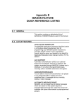
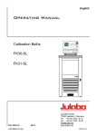
A block diagram of the main functional subsystems of the T1/
E1 card appears in Figure 4-1, below.
4-7
76-110-0685/F, Issue 1
M o th e rb o a rd
in te rfa ce
F o u r-w ire
in terfa c e
fro m /to
c a rrie r
Notes:
• M icro p ro c e ss o r, M a ilb o x,
RX
S w itc hin g
s u b sy ste m
C a rrie r
inte rfa ce
TX
a n d b ro k e n lin e s
(
) c o n n e c tin g
th e m , a p p ly o n ly to
P R I2 4 /P R I3 0 ca rd s.
• D a s h e d lin e s (
M icro p ro c e ss o r
bus
M ic ro pro c e ss o r
D ig ita l P h a se
L oc ke d L o op
a nd tim ing u n it
C lo ck b us
M ic ro co n tro lle r
bus
M a il b o x
)
c o n n e c tin g C a rrie r in te rfa c e to M ic ro c o n tro lle r
b u s a p p ly o n ly to
T 1 /E 1 c a rd s .
P C M c lo c k, P C M
sy n ch ron iza tion ,
rec o ve re d re fe re nc e
to M P D c a rd .
D igita l s ig n a l
p ro ce s so r
(C a ll p rog re s s
ton e d e te cto rs)
M ic ro c on tro lle r
S ys te m L A N
Figure 4-1 T1/E1 card and PRI24/PRI30 card functional block diagram
Carrier interface
The carrier interface controls signal coding and decoding,
frame and multiframe alignment and T1/E1 link layer
synchronization to the carrier.
The carrier interface includes elements which are controlled
and monitored by the system standard 8-bit microcontroller.
They do the following:
•
•
•
•
•
•
•
•
make the connection between the T1 card and the line;
protect the card from high voltage;
direct data and clock recovery;
provide for line length selection;
control local and remote loop-back testing;
act as a T1/E1 controller to insure frame alignment;
enable transmission of the Alarm Indicator Signal (AIS -Blue alarm);
control signaling.
Switching subsystem
The switching subsystem provides a PCM switching matrix
to access all of the time slots on all of the highways. The T1/
E1 card can access up to 12 highways via its two 64-pin
motherboard connectors.
4-8
Section 4: PERIPHERAL CARDS
Timing unit
The timing unit provides the transmission clock that is used
by the primary interface. The timing is derived from the
Digital Phase Locked Loop (DPLL), which is located on the
MPD card.
Digital signal processor (Call Progress Tone Detectors)
The digital signal processor (DSP) services all channels (24
channels on T1 and 30 channels on E1) simultaneously. The
digital signal processor detects dial tone, ring back tone,
busy tone and error tone and is used for the Automatic Dialer
and Automatic Redial features of the DIGITAL system.
Microcontroller
See Section 4.2 above, for peripheral card common
resources.
Memory unit
See Section 4.2 above, for peripheral card common
resources.
Jumpers
The T1/E1 card has one jumper. Jumper W1 is located
adjacent to the RJ45 connector, and is for future use.
EMI and Radio Frequency Interference grounds
See Section 4.2 above, for peripheral card common
resources.
Card connectors
The following connectors are mounted on the T1/E1 card.
•
DB15 connector
The female DB15 connector (JP1) is used to connect the
T1/E1 card to the Channel Service Unit (CSU) or network.
•
RJ48C connector
The female RJ48C connector (JP2) is one of the
connectors that is used to connect the T1/E1 card to the
Channel Service Unit (CSU) or network. This connector
appears only on style C0 and higher cards.
NOTE
The female RJ48C and DB15 connectors
are connected in parallel.
4-9
76-110-0685/F, Issue 1
•
64-pin connectors
In two- and three-cabinet DIGITAL 400 systems, where a
SAX is installed on the main motherboard of the middle or
lower cabinet, respectively, place the T1/E1 card in slot 2
or 3 of the middle cabinet or in slot 1, 2 or 3 of the lower
cabinet. In this way, the higher of the two 64-pin
connectors (J2) on the T1/E1 card connects to the SAX,
thereby providing access to additional highways.
The lower 64-pin connector (J1) is used to connect the
T1/E1 card to the main motherboard in both the DIGITAL
KEY BX and DIGITAL 400 systems.
LEDs
Table 4-2, below, lists the number, color and name of each
of the five LEDs on the T1/E1 card and defines the function
of each LED.
Provisioning considerations
See Table A-1 for port type limitations and definitions in
Appendix A.
T1/E1 card applications
The T1/E1 card has two applications:
•
Connecting the DIGITAL system to the Central Office;
NOTE
The T1/E1 card must be cabled to a
Channel Service Unit (CSU) and from the
CSU to the Central Office. The CSU is not
provided by Telrad.
•
Connecting two or more DIGITAL systems and PBXs in a
network.
For further information on T1/E1 card applications, their
configuration and installation alternatives, refer to the
DIGITAL Family of Systems Administration manual and the
DIGITAL Installation manual.
4-10
Section 4: PERIPHERAL CARDS
Table 4-2
T1/E1 LED definitions
LED No.
4.6
COLOR
NAME
FUNCTION
When the led is not lit, the card is
operating properly.
1 (Lower
LED)
RED
Card
running
2
RED
Loopback LED lights to indicate a
loopback, during corresponding
maintenance testing.
3
GREEN
OK
4
RED
Red alarm If the LED is lit, the T1/E1 card is
in "red alarm state" and is not
able to receive signals (i.e., loss
of synchronization).
5
YELLOW Yellow
alarm
If the LED is lit, the exchange at
the far end is not able to receive
your signal (i.e. the far end has
sent a remote alarm).
6
RED
This LED appears on style A-4
cards, but is not operative.
None
If the LED is lit, the interaction
between the T1/E1 card and the
connected equipment (e.g.
Central Office or networked PBX
system) is functioning properly.
ISDN PRI24/PRI30 CARDS
A single DIGITAL system can have either an ISDN PRI24
(North America) or an ISDN PRI30 (Mexico/Europe) outside
line card. These cards must be compatible with the national
telephone system where the DIGITAL system is located.
Where approved by local authorities, a single system will
accept these cards.
•
•
The ISDN PRI24 (identified by a blue tab) is a Primary
Rate Interface card which provides LT-T (Line
Termination -- Trunk) mode interfaces for 23 64 kb/sec B
channels and a single D channel for signaling at
64 kb/sec. This provides a total of 1544 kb/sec (including
the frame alignment time slot), between the DIGITAL
system and the Central Office supplied ISDN outside
lines.
The ISDN PRI30 (identified by a blue tab) is a Primary
Rate Interface card which provides LT-T mode interfaces
for 30 64 Kb kb/sec B channels and a single D channel for
signaling at 64 kb/sec. This provides a total of 2048 Kb
per second (including the frame alignment time slot)
between the DIGITAL system and Central Office supplied
ISDN outside lines.
4-11
76-110-0685/F, Issue 1
Functional description
The PRI24/PRI30 cards’ main functions are to interface,
switch, route, process, and transmit the data sent to or from
the DIGITAL system's ISDN outside line and signaling
channels.
Main functional units
• Carrier interface;
• Switching subsystem;
• Timing unit;
• Digital signal processor;
• Control unit.
A block diagram of the main functional subsystems of the
PRI24/PRI30 card appears in Figure 4-1, above.
Carrier interface
The carrier interface controls signal coding and decoding,
frame and multiframe alignment and PRI24/PRI30 link layer
synchronization to the carrier.
The carrier interface includes elements (controlled and
monitored by the system standard 8-bit microcontroller)
which do the following:
•
•
•
•
•
•
•
make the connection between the PRI24/PRI30 card and
the line;
protect the card from high voltage;
direct data and clock recovery;
provide for line length selection;
control local and remote loopback testing;
act as a PRI24/PRI30 controller to insure frame
alignment;
control signaling.
Switching subsystem
The switching subsystem provides a PCM switching matrix
to access all of the time slots on all of the highways. The
PRI24/PRI30 card can access (via its two 64-pin
motherboard connectors):
•
•
up to eight highways on the motherboard in the DIGITAL
KEY BX system;
up to 12 highways in the system (eight on the
motherboard and four on the SAX.
Timing unit
The timing unit provides the clocks that are used by the
primary interface and switching subsystem components. The
timing is derived from the Digital Phase Locked Loop (DPLL),
located on the MPD card.
4-12
Section 4: PERIPHERAL CARDS
Digital signal processor (Call progress tone detectors)
The DSP services all 23 (or 30) channels simultaneously.
The digital signal processor detects dial tone, ring back tone,
busy tone and error tone. It is used for the Automatic Dialer
and Automatic Redial features of the DIGITAL 400 system.
(See the Feature Description Manual.)
Control unit
• One microcontroller for internal system and messages;
• One microprocessor for ISDN layers;
• The microcontroller and microprocessor are connected
by the mailbox link.
Flash memory
Two flash memories are as follows:
•
•
64K for internal system and messages;
256K for ISDN layers.
Static RAM (SRAM)
A 64K SRAM and a 256K SRAM store data messages sent
between ISDN outside line channels and the system.
Jumpers
The PRI24/PRI30 card has no jumpers.
EMI and Radio Frequency Interference grounds
See Section 4.2 above, for peripheral card common
resources.
Card connectors
The following connectors are mounted on the PRI24/PRI30
cards:
•
Type RJ48C
Each PRI24/PRI30 card is fitted with a RJ48C connector,
which is used to connect the card to a Channel Service
Unit (CSU), and through it to the Central Office.
•
64-pin connectors
In two- and three-cabinet DIGITAL 400 systems, where a
SAX is installed on the main motherboard of the middle or
lower cabinet, respectively, place the PRI24/PRI30 card
in slot 2 or 3 of the middle cabinet or in slot 1, 2 or 3 of the
lower cabinet. In this way, the higher of the two 64-pin
connectors (J2) on the PRI24/PRI30 card connects to the
SAX, thereby providing access to additional highways.
The lower 64-pin connector is used to connect the PRI24/
PRI30, ONS and HONS cards to the main motherboard.
4-13
76-110-0685/F, Issue 1
LEDs
The PRI24/PRI30 cards contain three pairs of LEDs,
corresponding to the 186 microprocessor and the 152
microcontroller, with indications as follows:
a. upper paired LED
♦
lefthand red LED and righthand red LED:
-- the card is plugged in, the code
* steady red
is not running
* flashing red -- the card is plugged in and the
code is running
b. middle paired LED -- Link Status LED indicators
♦
lefthand green LED:
* off
-- no synchronization
* steady green -- no alarms, the link is
synchronized
* flashing green -- no alarms and the link is both
synchronized and a clock
reference
♦
righthand yellow LED:
* steady yellow -- local alarm
-- no alarms
* off
c. lower paired LED
♦
lefthand red LED:
-* steady red
-* off
♦
righthand red LED:
-* steady red
-* off
in loopback state
not in loopback state
remote alarm
no remote alarms
Provisioning considerations
See Table A-1 for port type limitations and definitions, in
Appendix A.
4.6.1
The DIGITAL KEY BX system
A maximum of one PRI24/PRI30 card can be installed in
each system cabinet.
4.6.2
The DIGITAL 400 system
A maximum of four PRI24/PRI30 cards can be installed in
each system cabinet.
For further information on PRI24/PRI30 card applications,
their configuration and installation alternatives, refer to the
DIGITAL Family of Systems Administration manual,
Installation manual and Maintenance manual.
4-14
Section 4: PERIPHERAL CARDS
4.7
ANALOG E&M INTERFACE (EMD) CARD
The analog E&M interface (Type I and II A & B side
supported, wink start, dial delay, immediate) EMD card
provides the DIGITAL system interfaces to one of the
following:
•
•
four two-wire audio tie outside line ports;
two four-wire audio tie outside line ports.
The EMD card can be divided into the following functional
units:
•
•
•
•
•
Peripheral board controller;
Analog Central Office outside line interface (ACO);
Microcontroller;
Memory unit;
Call progress tone detector.
Peripheral Board Controller
See Section 4.2 above, for peripheral card common
resources.
Analog Central Office Outside line Interface
The Signal Processing Code Decoder (CODEC) Filter
(SICOFI) is a programmable hardware device, which is the
interface between the analog outer world and the inner digital
world. It can be programmed to customize outside line
circuits to suit different PBXs.
Microcontroller
See Section 4.2 above, for peripheral card common
resources.
Memory unit
See Section 4.2 above, for peripheral card common
resources.
Call progress tone detector
One detector services all of the four tie lines by using time
sharing under the control of the card's microcontroller. It
detects dial tone, ring back tones and busy tone, and is used
for Automatic Redial and Autodialer features.
Ground definition jumper
See Section 4.2 above, for information about the RS-232
ground definition jumper.
4-15
76-110-0685/F, Issue 1
LEDs
One LED is provided for each EMD card. When the LED is
lit, the card is operating properly.
EMI and Radio Frequency Interference grounds
See Section 4.2 above, for peripheral card common
resources.
Provisioning considerations
See Table A-1 for port type limitations and definitions, in
Appendix A.
4.8
ANALOG DIRECT INWARD DIALING (DID) CARD
The analog DID card provides the interface between the
DIGITAL system and the Central Office supplied incoming
analog DID outside lines. The DIGITAL 400 card provides
eight DID interfaces. Each port supports one DID outside
line, with wink start, dial delay, immediate, etc.
The DID includes a Subscriber Line Interface Circuit (SLIC).
This integrated circuit converts four-wire transmission from
the DIGITAL system to a two-wire transmission circuit.
External connectors
See Section 4.2, above.
EMI and Radio Frequency Interference grounds
See Section 4.2 above, for peripheral card common
resources.
Provisioning considerations
See Table A-1 for port type limitations and definitions, in
Appendix A.
4.9
ISDN SUBSCRIBER LINE TERMINATION MODE (BRS) CARD
The ISDN LT-S (Line Termination -- Subscriber) mode BRS
card (identified by a green tab) provides four S bus ISDN
interfaces between the DIGITAL system and up to eight
internal ISDN Terminal Equipment (TE) elements connected
to the system. Each bus can support two ISDN terminal
element devices.
Functional description
The BRS card’s main functions are to interface, switch,
route, filter, process and transmit the data sent to or from the
4-16
Section 4: PERIPHERAL CARDS
TE elements connected to it. The BRS card can be divided
into the following functional units:
• 2 Microcontrollers -one for the internal
system and messages;
one for ISDN layers;
• Flash memory;
• S bus interface;
• Peripheral board
controller;
• SRAM;
• Power Regulation unit.
Microcontroller
One microcontroller for internal system and messages;
one microcontroller for ISDN layers.
Flash memory
Two flash memories are as follows:
•
•
64K for internal system and messages;
256K for ISDN layers.
S bus interface
The S bus interface mediates between the internal protocol
used in the card and the ISDN protocol used by the S bus.
The interface employs Time Division Multiplexing (TDM) to
handle two voice channels (64 Kb/sec each channel) and
one data channel (16 Kb/sec) simultaneously.
Peripheral Board Controller
See Section 4.2 above, for peripheral card common
resources.
Static RAM (SRAM)
A 32K SRAM and a 256 K SRAM are used for handling card
procedures and ISDN.
Power Regulation Unit
Each port has an overcurrent regulation unit which
disconnects the telephone set if the current exceeds 300 mA.
The telephone set is reconnected automatically when the
current is reduced.
Similarly, telephone sets are disconnected if the voltage falls
below 24 V. The card’s microprocessor reconnects the sets
when the voltage returns to the proper level.
LEDs
Each of two red LEDs on the outer edge of the BRS card
indicates the operational status of one of the two
microcontrollers. A blinking LED indicates that the respective
microcontroller is active. A lit or unlit LED indicates that the
respective microcontroller is inactive.
4-17
76-110-0685/F, Issue 1
EMI and Radio Frequency Interference grounds
See Section 4.2 for peripheral card common resources.
Provisioning considerations
See Table A-1 for port type limitations and definitions, in
Appendix A.
4.10
ISDN TRUNK LINE TERMINATION MODE (BRT, BHT) CARDS
The ISDN Trunk Line Termination (LT-T) mode cards,
identified by a blue tab, provide the interface between the
DIGITAL System and the ISDN outside lines supplied by the
Public Exchange. Each card contains a number of ports. The
BRT card provides the interface for 4 outside lines. The BHT
card provides the interface for 2 outside lines.
These cards control both the B and the D channels of the
T interface and control the routing of signalling over the
ISDN U-interface and an ISDN S/T-Interface. (See Figure 42 below.)
Figure 4-2 NT-1 connection diagram for BRT and BHT
cards
Two types of Public Exchange ISDN Trunk cards are
available:
•
•
BRT - Supports four S bus ISDN ports;
BHT - Supports two S bus ISDN ports.
Functional description
The BRT and BHT cards’ main functions are to interface,
switch, route, filter, process, and transmit the data sent to or
from the DIGITAL system’s ISDN outside line channels. The
BRT and BHT cards can be divided into the following
functional units:
4-18
Section 4: PERIPHERAL CARDS
•
•
•
•
•
•
•
•
Timing unit;
2 Microcontrollers (one for the internal system and
messages, and one for ISDN layers);
Flash memory;
S bus interface;
Peripheral Board controller;
SRAM;
Timing unit;
Power Detection unit.
Timing unit
The timing unit provides the clock reference, used by the
Digital Phase Locked Loop (DPLL). The timing of the system
is derived from the DPLL, located on the MPD card. The
DPLL consists of a 2 MHz transmit clock generator.
Microcontroller
• One microcontroller for internal system and messages;
• One microcontroller for ISDN layers.
Flash memory
Two flash memories:
•
•
64K for internal system and messages;
256K for ISDN layers.
S bus interface
The S bus interface mediates between the internal protocol
used in the card and the ISDN protocol used by the S bus.
The interface employs Time Division Multiplexing (TDM) to
handle two voice channels (64 Kb/sec) and one data channel
(16 Kb/sec) simultaneously.
Peripheral Board Controller
See Section 4.2 above, for peripheral card common
resources.
Static RAM (SRAM)
A 64K SRAM and a 256 K SRAM are used for storing data
messages sent between ISDN outside line channels and the
system.
Power Detection Unit
The power detection unit detects the presence of power
(between 24V and 42V) on ISDN outside line channels.
LEDs
The BRT card contains six LEDs, one single-color (red) LED
for each of the two processors, and one dual color (green/
yellow) LED for each of the four interfaces. Their location is
as follows:
4-19
76-110-0685/F, Issue 1
♦
red LEDs -- Each of the two red LEDs on the outer
edge of the BRT and BHT cards indicates the
operational status of one of the two microcontrollers.
* lit -- indicates that the respective microcontroller is
powered on, but not running.
* blinking --indicates that the respective
microprocessor is running;
* unlit --indicates that the respective microprocessor
is inactive
♦
green/yellow dual color LEDs ---A dual color green/
yellow LED on the outer edge of BRT and BHT cards
indicates the operational status of each S bus ISDN
port on each card. i.e., four such LEDs on the BRT
card and two such LEDs on the BHT card.
* lit green --indicates that the respective S bus is
synchronized;
* blinking green -indicates that the respective S bus
is active and serves as the synchronization
reference guided by the MPD card’s DPLL unit;
* lit yellow - indicates that the respective S bus is
powered on, but synchronized;
* unlit yellow --indicates that the respective S bus is
not powered.
Radio Frequency Interference grounds
See Section 4.2 above, for peripheral card common
resources.
Provisioning considerations
See Table A-1 for port type limitations and definitions, in
Appendix A.
4.11
EXECUTIVE LINE CIRCUIT (ELD AND EHD) CARDS
The Executive Line Circuit card provides the interface
between the proprietary digital family of telephone sets and
the DIGITAL system. Each card contains a number of ports,
each of which can support up to two telephone sets,
depending on the particular installation configuration. See
Table A-1 in Appendix A.
The ELD card controls both the B and the D channels of the
S-interface. The ELD card controls the routing of packet
switched data over the D channel. The card is supplied in two
versions:
4-20
Section 4: PERIPHERAL CARDS
•
•
ELD -- The 8-port ELD card supports eight S-buses and
provides interfaces for up to 16 proprietary digital
telephone sets.
EHD -- The 4-port EHD card is similar to the ELD card,
but supports four S-buses and provides interfaces for up
to eight proprietary digital telephone sets.
Functional description
The ELD/EHD cards’ main functions are to interface, switch,
route, filter, process, and transmit the data sent to or from the
DIGITAL system's proprietary digital telephone sets. The
ELD/EHD can be divided into the following functional units:
•
•
•
•
•
•
Microcontroller;
EPROM;
S bus interface;
Peripheral Board controller;
SRAM;
Power Regulation unit.
Microcontroller
See Section 4.2 for peripheral card common resources.
EPROM
See Section 4.2 for peripheral card common resources.
S bus interface
The S bus interface mediates between the internal protocol
used in the card and the ISDN protocol used by the S bus.
The interface employs Time Division Multiplexing (TDM) to
handle two voice channels (64 Kb/sec each channel) and
one data channel (16 kb/sec), simultaneously.
Peripheral Board controller
See Section 4.2 above, for peripheral card common
resources.
Static RAM (SRAM)
A 64K SRAM, consisting of two 32K components is used for
storing data messages sent between telephone sets and the
system.
Power regulation unit
Each port has an overcurrent regulation unit which
disconnects the telephone set if the current exceeds 300 mA.
The telephone set is reconnected automatically when the
current is reduced.
Similarly, telephone sets are disconnected if the voltage falls
below 35 V. The card's microprocessor reconnects the sets
when the voltage returns to the proper level.
4-21
76-110-0685/F, Issue 1
EMI and Radio Frequency Interference grounds
See Section 4.2 above, for peripheral card common
resources.
Provisioning considerations
See Table A-1 for port type limitations and definitions, in
Appendix A.
4.12
EXECUTIVE LINE ANALOG (ELA) CARD
The Executive Line Analog card provides the interface
between a family of Telrad's analog telephone sets and the
DIGITAL system. Each card contains eight ports and can
support up to eight single audio path (SAP) or dual audio
path (DAP) analog telephone sets, with no more than one set
connected to each port.
Functional description
The ELA card's main functions are to interface, switch, route,
filter, process, and transmit the data sent to or from the
analog telephone sets connected to the DIGITAL system.
The ELA card can be divided into the following functional
units:
•
•
•
•
•
•
Microcontroller;
EPROM;
Telephone set interface;
Peripheral Board controller;
SRAM;
Power Regulation unit.
Microcontroller
See Section 4.2 above, for peripheral card common
resources.
EPROM
See Section 4.2 above, for peripheral card common
resources.
Telephone set interface
The telephone set analog interface provides audio and
handsfree communications via two telephone set pairs and
data communication via the third telephone set pair. Power
feed to the telephone sets is provided via the data link and
the main audio link by a phantom connection.
Peripheral Board controller
See Section 4.2 above, for peripheral card common
resources.
4-22
Section 4: PERIPHERAL CARDS
Static RAM (SRAM)
A 64K SRAM, consisting of two 32K components is used for
storing data messages sent between telephone sets and the
system.
Power regulation unit
Telephone sets are disconnected if the voltage falls below
35 V. The card's microprocessor reconnects the sets when the
voltage returns to the proper level.
EMI and Radio Frequency Interference grounds
See Section 4.2 above, for peripheral card common
resources.
Provisioning considerations
See Table A-1 for port type limitations and definitions, in
Appendix A.
4.13
SLD AND SHD CARDS
The SLD and SHD cards provide the interface between the
DIGITAL system and eight industry standard, type 500
(impulse) or type 2500 (tone) single line telephones located
within 3.6 miles of the system cabinet. These telephones can
be on premise extensions or off-premise extensions (OPXs).
(The OL13C circuit code is given to the central office when
ordering OPX circuits).
The cards also provide the SLD communications protocol,
SLT operating and signaling voltages and protection against
voltage surges.
The SLD and SHD card are also used to connect
announcers, VS&F, external modems, fax machines, etc.
The SLD and SHD cards provide the following SLT support
services:
• Route ring voltage from
either the:
♦
external ringer unit to
SLTs connected to the
SLD card; or
♦ built-in ringer on the
SHD card to SLTs
connected to this card;
• Onhook/offhook status
detection;
• Turn on the message
indicator -- on SLTs
connected to the SLD
card only;
• Hook flash detection;
• Assign ring and tone rates
for each SLT;
• Identify DTMF tones;
• Identify impulse dialing.
4-23
76-110-0685/F, Issue 1
The SLD and SHD cards can be divided into the following
functional units:
• Microcontroller;
• Memory unit;
• Peripheral Board
controller;
• Power supply unit;
• Analog SLT interface;
• DTMF receivers.
Microcontroller
See Section 4.2 above, for peripheral card common
resources.
Memory unit
See Section 4.2 above, for peripheral card common
resources.
Peripheral Board controller
The Peripheral Board controller (PBC) mediates between the
microcontroller and the SLIC to transmit the audio and
control signaling.
Power supply unit, SLT ringer and SLT message lamp
generator
• Power sources
The SLD card includes the following power sources for:
♦
internal or external ringer: 86 V RMS, 20 Hz
ringing voltage;
♦
message module: -110 V DC voltage.
•
External ringer
If a Telrad external ringer is connected to the system, a
ringer daughterboard can be mounted on an SLD card.
The 4-pin connector on the ringer daughterboard must be
wired to the external ringer.
One external ringer can serve up to 96 SLTs connected
to SLD, ONS or HONS cards.
•
Message lamp generator
The power for the SLTs’ message lamp indicators
connected to SLD cards is supplied via a message lamp
generator built in to the card.
The SHD card does not support SLT message lamps.
A summary of available methods of supplying ringer and
message lamp power to SLTs connected to either SLD,
SHD, ONS or HONS cards is shown in Table 4-3, below.
4-24
Section 4: PERIPHERAL CARDS
Table 4-3
SLT ringer and message lamp support summary
Card type
Device
Method
SLD SHD ONS HONS
4-pin connector built-in on the card
--
--
X
X
mount onto the card -- on site -- the ringer daughterboard
with its 4-pin connector,
for connection to the external ringer
X
--
--
--
Message message lamp generator built-in on the card
lamp
mount the message lamp generator daughterboard onto
generator the card -- on site
V
--
--
--
--
--
X
X
External
ringer
The analog SLT interface
The card includes a SICOFI component which performs the
analog-digital conversion. It also includes a SLIC
component, which converts four-wire transmission of a
DIGITAL system to two-wire transmission of SLTs.
DTMF receivers
Each SLD and SHD card includes two DTMF receivers which
interpret DTMF dialing of SLTs.
Jumpers (on SLD card only)
The W100 - W800 jumper is normally in place to enable
message voltage. The jumper must be removed to cancel
message voltage if the SLT is defined as an OPX. One
jumper is provided for each port.
EMI and Radio Frequency Interference grounds
See Section 4.2 for peripheral card common resources.
Provisioning considerations
See Table A-1 for port type limitations and definitions, in
Appendix A.
One ringer is required for any DIGITAL 400 system cabinet
containing SLTs.
4.14
ONS AND HONS CARDS
Functional description
The on-site ONS and HONS cards provide the interface
between the individual industry standard 500 or 2500 model
on site SLT telephones, located up to 3.0 miles from the
system cabinet and the DIGITAL system. The number of SLT
ports supported by these cards are as follows:
4-25
76-110-0685/F, Issue 1
•
•
ONS -- 16;
HONS -- 8.
NOTE
ONS/HONS circuits cannot be used for
OPX connections.
The cards also provide the ONS communications protocol,
SLT operating and signaling voltages and protection against
voltage surges.
The ONS and HONS cards provide the following SLT
support services:
• Onhook/offhook status
detection;
• Hook flash detection;
• Route ring voltage from
the ringer unit to SLTs;
• Assign ring and tone rates
for each SLT;
• Identify DTMF tones;
• Identify impulse dialing.
The ONS and HONS cards can be divided into the following
functional units:
• Microcontroller;
• Memory unit;
• Peripheral Board
controller;
• Power supply unit;
• Analog SLT interface;
• DTMF receivers.
Microcontroller
See Section 4.2 above, for peripheral card common
resources.
Memory unit
See Section 4.2 above, for peripheral card common
resources.
Peripheral Board controller
The Peripheral Board controller (PBC) mediates between the
microcontroller and the SLIC for the purpose of transmitting
the audio and control signaling.
64 pin connector
Two 64-pin connectors are mounted on the rear of ONS and
HONS cards, for connection to the SAX motherboard.
RS-232 daughterboard
A daughterboard can be connected to an ONS or HONS
card. It has an RS-232 configured serial communication port
to provide connection with an SMDR printer.
4-26
Section 4: PERIPHERAL CARDS
Power supply unit, SLT ringer and SLT message lamp
generator
• Power sources
The ONS and HONS cards include the following power
sources for:
* internal or external ringer: 86 V RMS, 20 Hz
ringing voltage;
* message module: -110 V DC voltage.
•
External ringer
If a Telrad external ringer is connected to the system, the
4-pin external connector on an ONS or HONS card can
be wired to the ringer.
One external ringer can serve up to 96 SLTs connected
to SLD, ONS or HONS cards.
•
Message lamp generator
A message lamp indicator daughterboard unit must be
installed on each ONS and HONS card to which SLTs
with message lamps are connected.
For a summary of available methods of supplying ringer
and message lamp power to SLTs connected to either
SLD, SHD, ONS or HONS cards, see Table 4-3, above.
The Analog SLT interface
The card includes a SICOFI component which performs the
analog-digital conversion and a SLIC component, which
converts four-wire transmission of DIGITAL system to twowire transmission of SLTs.
DTMF receivers
Each ONS and HONS card includes two DTMF receivers
which interpret DTMF dialing of SLTs.
Jumpers
None.
EMI and Radio Frequency Interference grounds
See Section 4.2 above, for peripheral card common
resources.
Provisioning considerations
See Table A-1 for port type limitations and definitions, in
Appendix A.
One ringer is required for any DIGITAL KEY BX system
containing SLTs.
4-27
76-110-0685/F, Issue 1
In the DIGITAL 400 system, one ringer is required for 96
SLTs.
4.15
OPTION CARD (OCD)
The OCD card serves as a physical and logical platform for
the DIGITAL system option modules. The OCD card
operates at a maximum baud rate of 9600 bps (D style). You
can program the old baud rate to match the peripheral
equipment it is supporting.
The following are the DIGITAL system option modules:
•
•
•
Multiple Interface Module (MIM), which support audio
channels, sensors and relays, for connection of door
units, external page zones, external bells, IMAGEN, and
MOH/BGM port;
one modem module per system, for remote
administration and maintenance, with a baud rate of 2400
bps modem module;
a DTMF module, containing four DTMF receivers.
The option modules are units with connecting pins. Each
module contains its own firmware. Each module has its own
LED.
Each OCD card can contain up to three modules of any type.
The option modules are described below.
The 2400 baud modem module and the DTMF receiver
modules attach to the OCD card without any other
preparation. The MIM module is described in further detail in
the DIGITAL Installation manual.
Provisioning considerations
DIGITAL KEY BX system A maximum of three OCD cards
can be installed in the system. Each OCD card can support
up to three option modules. A maximum of nine Option
modules can be installed in the system.
DIGITAL 400 system A maximum of ten OCD cards can be
installed in the system. Each OCD card can support up to
three option modules. A maximum of 30 Option modules can
be installed in the system. For further details on provisioning
considerations, see Appendix A.
4.16
MULTIPLE INTERFACE MODULE (MIM)
The MIM provides the software and hardware resources
required to connect external devices such as IMAGEN, door
4-28
Section 4: PERIPHERAL CARDS
units, external page, MOH/BGM and external bells to a
DIGITAL system.
The hardware resources provided include four two-wire
duplex audio channels, two relays, and two sensors.
Resource requirements
The MIM provides four audio channels. The IMAGEN cards
come in 2 or 4 port models which use 2 or 4 audio channels.
Door unit interface: One two-wire audio channel, two relays,
and one sensor.
External page interface: One simplex audio channel and one
relay.
External bell interface: One relay.
External connector: The Multiple Interface Module (MIM) has
an RCA female connector for MOH/BGM.
DIP switches
DIP (Dual In Line Package) switches are located on the
bottom of the module on the module surface containing the
connecting pins. DIP switches define the relay path. For
example, the DIP switches enable designation of relay #2 as
"normally open" (NO) or "normally closed" (NC).
Provisioning considerations
DIGITAL KEY BX system Up to five MIM modules can be
programmed in the system.
A maximum of three MIM modules can be used for
connecting IMAGEN.
A maximum of two MIM modules can be used for connecting
external equipment.
Each IMAGEN port used must be included in the maximum
number of 96 extension ports which can be supported by the
system. See Table A-1 for summary of port type limitations
and definitions.
DIGITAL 400 system A maximum of 12 MIM modules can
be programmed in the system. A maximum of four MIM
modules can be used for connecting IMAGEN.
A maximum of eight MIM modules can be used for
connecting external equipment.
4-29
76-110-0685/F, Issue 1
Each IMAGEN port used must be included in the maximum
number of 254 extension ports which can be supported by
the system. See Table A-1 for a summary of port type
limitations and definitions.
4.17
MODEM MODULE
The 2400 bps modem module provides the DIGITAL system
with an internal modem for remote administration and
maintenance.
The 2400 bps Modem Module is a proprietary device using
the following:
•
•
V22.bis, V22 communications protocol, MNP 2-4 and
V42 error correction and detection protocols;
MNP 5 and V42.bis compression/decompression
protocols.
External connector
The modem module has no external connector.
Provisioning considerations
Only one modem module can be included in an entire
DIGITAL system.
DIGITAL KEY BX system When a modem module is used,
it must be included in the maximum number of 96 extension
ports which can be supported by the system. See Table A-1
for a summary of port type limitations and definitions.
DIGITAL 400 system When a modem module is used, it
must be included in the maximum number of 254 extension
ports which can be supported by the system. See Table A-1
for a summary of port type limitations and definitions.
4.18
DTMF MODULE
Each DTMF module provides the DIGITAL system with four
independent DTMF receivers which recognize 16 different
tone pairs.
Provisioning considerations
The permissible number of DTMF modules to be installed
(with four DTMF receivers each) depends on the number of
SLD, SHD, and DID cards in the system and the use of
DTMF receivers on those cards. This limitation is determined
by the location of other DTMF receivers, as follows:
•
4-30
one on the MPD card;
Section 4: PERIPHERAL CARDS
•
two on each DID, SLD, SHD, ONS and HONS card.
4.18.1 The DIGITAL KEY BX system
The maximum number of DTMF receivers in the system is
17. The maximum number of DTMF modules in the system
is four. A maximum of nine DTMF receivers will be allocated
for the entire system, using the MPD, SHD, SLD or DID
cards, when no DTMF modules or ONS/HONS cards have
been installed.
This limitation is determined by the location of DTMF
receivers (up to a total of 17 DTMF receivers in the system)
as follows:
•
•
•
one on the MPD card;
two on each DID, SLD, SHD, ONS and HONS card;
four on each DTMF module.
4.18.2 The DIGITAL 400 system
The maximum number of DTMF receivers in the system is
37. The maximum number of DTMF modules in the system
is nine.
A maximum of nine DTMF receivers will be allocated for the
entire system, using the MPD, SHD, SLD or DID cards, when
no DTMF modules or ONS/HONS cards have been installed.
This limitation is determined by the location of DTMF
receivers (up to a total of 37 DTMF receivers in the system)
as follows:
•
•
one on the MPD card;
two on each DID, SLD, SHD, ONS and HONS card; four
on each DTMF module.
4-31
76-110-0685/F, Issue 1
THIS PAGE INTENTIONALLY LEFT BLANK
4-32
Section 5
POWER SUPPLY
5.1
POWER SUPPLY UNIT
The internal power supply unit, located in each installed
system cabinet, converts the 110 Vac/60 Hz (North America)
or 230 Vac/50Hz (Europe) input power into the DC voltages
for the cards and terminal equipment. Figure 5-1 shows the
power supply units for both the DIGITAL KEY BX system and
the DIGITAL 400 system.
The power supply unit supplies ±5V for the logic circuitry of
the system as well as -48V for the proprietary digital and
analog telephone sets. The -48V serves as line voltage for
SLD, SHD, ONS and HONS cards, and is used to generate
ringer voltage via the ringer module on one of the SLD, SHD,
ONS and HONS cards. The 110V message waiting voltage
for SLT telephone sets is converted, from -48V, on the SLD,
SHD, ONS and HONS cards containing the ringer module.
The power supply unit uses hybrid linear/switching
technology to generate the -48V and the ±5V.
5.2
BATTERY BACKUP UNIT (BBU)
A BBU is available only for the DIGITAL KEY BX system.
When a BBU is connected to the system, a special power
supply unit is installed. It contains backup and control circuit
and is installed in, or next to, one of the system cabinets. The
battery pack cable is connected to the special power supply.
The two-hole -48 Vdc connector on the front panel of the
DIGITAL 400 power supply (shown in Figure 5-1) can be
used to connect a customer supplied BBU to the system.
5-1
76-110-0685/F, Issue 1
5.3
UNINTERRUPTABLE POWER SUPPLY (UPS)
A UPS can be installed as a backup for the power supply,
with a power capacity suited to the DIGITAL system and the
number of system cabinets, as follows:
•
•
DIGITAL KEY BX system (150 VA per system cabinet);
DIGITAL 400 system (500 VA per system cabinet).
Figure 5-1 DIGITAL KEY BX and DIGITAL 400 power supply units
5-2
Section 5: POWER SUPPLY
5.4
POWER SUPPLY EXTERNAL CONNECTORS AND SWITCHES
An ON/OFF switch is lit when the power supply unit is
operational.
In the DIGITAL KEY BX system cabinet, a cable terminating
in a 12 pin female connector, connects the power supply to
the motherboard.
In the DIGITAL 400 system cabinet, the power supply is
inserted into the system cabinet. A connector on the rear of
the power supply plugs into its counterpart connector on the
main motherboard, similarly to the card insertion.
The power socket includes an RFI noise filter for connecting
the power supply unit to the power source cable.
A power outlet is provided for supplying power to the linked
cabinets in a multicabinet system. (This applies to the
DIGITAL KEY BX system only.)
Each power supply unit has a six foot long power source
cable which plugs into the power socket or the power supply,
on one end, and the power source outlet or the adjacent
cabinet power supply (DIGITAL KEY BX) or power strip on
the wheel unit (DIGITAL 400), on the other.
Linking system cabinets
See Section 3. 4 above.
5.5
POWER SUPPLY PROVISIONING CONSIDERATIONS
One power supply unit is required per system cabinet.
5-3
76-110-0685/F, Issue 1
THIS PAGE INTENTIONALLY LEFT BLANK
5-4
Section 6
TERMINAL EQUIPMENT
6.1
INTRODUCTION
This section provides a description of the common features
of the telephone sets together with specific details of each
telephone set.
Two families of telephone sets are available to users in a
DIGITAL system; a digital family and an analog family.
The options available for each telephone set in each family
are detailed in Table 6-1 below. The map abbreviation
column, on the right, gives the abbreviation used for each
telephone set in the administration maps.
Various alternative configurations of the digital and analog
telephone sets are presented in Section 8.1.
6-1
76-110-0685/F, Issue 1
Table 6-1
Summary of telephone set characteristics
number of program- audio
map
available
mable keys or
path abbreviation in options
softkeys
PCP
display
text
D S
Add
size
section figure
A A
-on data
no.
P P
unit card
no.
reference
family
Digital
Analog
set type
Executive set
without display
Section
6.3.3
6-1
--
36
X
X
EXD
X
X
Executive set
with expanded
display
Section
6.3.1
6-1
8 x 24
36+12 soft
X
X
EXD
X
X
Executive set with Section
display
6.3.2
6-2
2 x 24
36+10 spd
X
X
EX1
X
X
Display
Speakerphone
set
Section
6.4.1
6-3
2 x 16
16
X
X
SD
X
X
Speakerphone
set
Section
6.4.2
6-4
--
16
X
X
SD
--
X
16 Button set
Section
6.5.1
6-5
--
16
X
SD
--
--
4 Button set
Section
6.5.2
6-6
--
4
X
BA
--
--
Executive station
Section
6.6.1
6-7
1 x 16
24
X
EX
--
--
Standard display
station
Section
6.6.2
6-7
1 x 16
16
X
ST
--
--
Basic Key set
Section
6.6.3
6-8
--
16
X
BK
--
--
FB
--
--
Four Button Plus
set with
speakerphone
Four Button Plus
set w/o
speakerphone
X
Section
6.6.4
6-9
SLT
Single line
telephone
Section
6.7
Telrad
Tracker
Cordless Station
Section 6-10
6.8
6.1.1
--
--
--
--
4
-4
--
X
--
X
--
--
--
X
SD
--
--
The digital family of telephone sets
The digital family of telephone sets in the DIGITAL systems
are custom designed for use with these systems. The
common features of the telephone sets in this family and
those of each set type are discussed below.
6-2
Section 6: TERMINAL EQUIPMENT
6.1.2
The analog family of telephone sets
The telephone sets of the analog family are supported by the
DIGITAL systems, as well. The common features of the
telephone sets in this family and those of each set type are
discussed below.
6.2
COMMON FEATURES OF DIGITAL TELEPHONE FAMILY SETS
6.2.1
Technology
Each of the digital telephone family sets contains an 8051
microprocessor, which supports data signaling between the
sets and the system cabinet. Digital conversion is performed
in the sets. The sets are compatible with ISDN level one
(Physical layer).
6.2.2
Hardware
The proprietary telephone sets consist of the following:
•
•
•
•
•
•
a base fitted with a cradle and handset;
a speaker;
a microphone;
a dial pad;
fixed feature buttons;
programmable buttons (which can be defined as feature
buttons, direct station selection (DSS) buttons or speed
dialing (SPD) buttons).
The status of a feature, extension or outside line, allocated to
a programmable button, is indicated by a single or dual-color
(red/green) LED. The LED flash rate provides the user with
additional status information.
In addition to the various fixed and programmable buttons, all
sets have a feature button which, in conjunction with the
appropriate feature code, enables the user to access any
system feature.
The upper panel may contain extra buttons or variously sized
displays, depending on the particular telephone set model.
On some sets, this upper panel is adjustable. All sets have a
multifunction [<LO HI>] button which regulates the
following:
•
•
•
display contrast (if operated while the telephone is not in
use), ringing volume (if operated during ringing);
speaker volume (if operated while speaker is in use);
handset volume (if operated while the handset is in use).
6-3
76-110-0685/F, Issue 1
The [<LO HI>] button is also used to scroll messages when
reading more than one message.
Each set contains its own memory, both nonvolatile (EPROM
and ROM) and volatile (RAM). The nonvolatile memory is
used to store the telephone set's directory number (DN)
profile identification. The DN uniquely identifies the set and
is used by the system to verify set compatibility with the line
when the system is reset or when the set is reconnected to
the line. The memories provided for each type of telephone
set, are detailed below:
Display
Executive Speakerphone and
Speakerphone
16 Button
and
4 Button
ROM
8K/2K
8K
8K
RAM
2K
2K
--
YES
YES
YES
EPROM
The sets operate with an internal proprietary protocol which
supports the features specific to a DIGITAL system.
Telephone sets are supplied with several labels to enable the
user to customize the programmable buttons.
All the telephone sets can be wall mounted. They are
supplied in one of two colors (gray or black) and a choice of
handsets.
6.3
THE DIGITAL FAMILY EXECUTIVE SETS
6.3.1
Executive set with expanded display
The Executive set with expanded display (See Figure 6-1) is
a multibutton digital telephone set with an expanded display
for softkey operation and speakerphone. Single channel
Universal data cards and TAPI/TelradLINK data cards
installed in this telephone set perform protocol conversion.
This enables a PC to connect to the DIGITAL system and
operate with appropriate Telrad Console, DIGITAL, CSD,
TAPI, TSAPI, TelradLINK, CSV or ACD I.Q. software.
The set can be configured for either a single audio path
(SAP) or a dual audio path (DAP). The set supports offhook
voice announce with handsfree answerback.
6-4
Section 6: TERMINAL EQUIPMENT
In addition to the standard 12-button dialpad, the Executive
set with expanded display features ten fixed function buttons,
28 programmable buttons with dual-color LEDs and eight
with single color LEDs, six menu-driven softkeys, and six
worktable softkeys.
The adjustable display panel has an eight line by 24
character dot matrix, liquid crystal display (LCD) which
provides two rows of information (time, date, call progress
indications, etc.). It also has software controlled prompts for
the six softkeys mounted on either side of the display.
6-5
76-110-0685/F, Issue 1
Figure 6-1 Executive set with expanded display and Executive set without
display
6-6
Section 6: TERMINAL EQUIPMENT
Softkeys change their function dynamically, depending on
the current status of a call. You can operate more than 30
features from just six softkeys. In addition, softkeys simplify
set operation by showing all the currently valid options.
Features not currently applicable are not displayed.
Additional softkey prompts for IMAGEN, Electronic Business
Card, and System Dial By Name (SDBN), caller ID list and
caller features appear on the set's expanded display when
the software for that option is installed.
The Executive set can be enhanced further by attaching up
to four 36 button Add-on units (See Figure 6-12).
6.3.2
The Executive set with display
The Executive set with display (See Figure 6-2) is equipped
with a two line by 24 character dot matrix liquid crystal
display (LCD). It provides information as to time and date,
call destination status, call progress status and other call
indications. The adjustable display panel contains ten speed
dial buttons in addition to the 36 programmable buttons on
the telephone set's base.
Single channel Universal data cards and TAPI/TelradLINK
data cards installed in this telephone set, perform protocol
conversion. This enables a PC to connect to the DIGITAL
system and operate with appropriate CSD, TAPI, TSAPI,
TelradLINK, CSV or ACD I.Q. software.
The set can be configured for either a single audio path
(SAP) or a dual audio path (DAP). The set supports offhook
voice announce with handsfree answerback.
The Executive set with display can be enhanced further by
attaching up to four 36 button Add-on units (See Figure 612).
6.3.3
The Executive set without display
The Executive set without display has a a non-adjustable,
sealed upper panel with neither a display nor buttons. The 36
programmable button arrangement on the telephone set's
base is identical to that of the other two Executive sets. (See
Figure 6-1.)
Single channel Universal data card and TelradLINK data
cards installed in this telephone set, perform protocol
conversion. This enables a PC to connect to the DIGITAL
system and operate with appropriate Telrad Console, CSD,
TAPI, TSAPI, TelradLINK, CSV or ACD I.Q. software.
6-7
76-110-0685/F, Issue 1
Figure 6-2 Executive set with display
The set can be configured for either a single audio path
(SAP) or a dual audio path (DAP). The set supports offhook
voice announce with handsfree answerback.
The Executive set can be enhanced further by attaching up
to four 36 button Add-on units (See Figure 6-12).
6-8
Section 6: TERMINAL EQUIPMENT
6.4
THE DIGITAL FAMILY SPEAKERPHONE SETS
6.4.1
Display Speakerphone set
The Display Speakerphone set (See Figure 6-3) is also
equipped with the standard dialpad and adjacent fixed
function buttons. The four programmable buttons, in the row
above the dialpad, have dual color LEDs.
The Display Speakerphone set has twelve programmable
buttons situated on the flat upper panel, with a two line by 16
character LCD display, sloped at a convenient fixed angle, at
the upper end of the panel. The twelve programmable
buttons on the upper panel incorporate dual-color LEDs to
indicate the status of each button's programmed feature.
The display provides the same time, date and call progress
information as provided by the Executive sets.
Single channel Universal data cards and TAPI/TelradLINK
data cards installed in this telephone set perform protocol
conversion. This enables a PC to connect to the DIGITAL
system and operate with appropriate CSD, TAPI, TSAPI,
TelradLINK, CSV or ACD I.Q. software.
The set can be configured for either a single audio path
(SAP) or a dual audio path (DAP). The set supports offhook
voice announce with handsfree answerback.
The Display Speakerphone set can be enhanced further by
attaching up to four 36 button Add-on units (See Figure 6-12).
6.4.2
Speakerphone set
The Speakerphone set (See Figure 6-4) has no display and
cannot accept a 36 button Add-on unit. In all other respects,
it is identical to the Display Speakerphone set.
6-9
76-110-0685/F, Issue 1
Figure 6-3
6-10
Display Speakerphone telephone set
Section 6: TERMINAL EQUIPMENT
Figure 6-4 Speakerphone set
6-11
76-110-0685/F, Issue 1
6.5
THE DIGITAL FAMILY 16 BUTTON AND FOUR BUTTON SETS
6.5.1
16 Button set
The 16 Button set (See Figure 6-5) provides twelve
programmable buttons with dual color LEDs on its upper
panel. The set has handsfree answerback capability. In
addition to the standard dialpad, adjacent fixed function
buttons and the four programmable function buttons in the
row above the dialpad.
The 16 Button set cannot accept a data card or a 36 button
Add-on unit.
6.5.2
Four Button set
The Four Button set (See Figure 6-6) has the standard
dialpad and adjacent fixed function buttons and four
programmable buttons with dual color LEDs in the row above
the dialpad. The Four Button set allows the user to access all
the system features by pressing the [FEAT] button and
dialing the feature code. The set has handsfree answerback
capability.
The Four Button set cannot accept a data card or a 36 button
Add-on unit.
6-12
Section 6: TERMINAL EQUIPMENT
Figure 6-5 16 Button set
6-13
76-110-0685/F, Issue 1
Figure 6-6 Four Button set
6-14
Section 6: TERMINAL EQUIPMENT
6.6
THE ANALOG FAMILY TELEPHONE SETS
In addition to the proprietary telephone sets created
expressly for the DIGITAL systems, the systems support
operation of four types of proprietary analog stations, as
follows:
•
•
•
•
6.6.1
Executive Station;
Standard Display Station;
Basic Key Set (with or without speakerphone;
Four Button Plus Station (with or without speakerphone).
The analog family Executive station
The analog family Executive station is a multibutton,
microprocessor based, telephone featuring two Liquid
Crystal Displays (LCDs) and full speakerphone capability
(See Figure 6-7). The Executive station can handle two
conversations, using both the audio path and the handsfree
path, simultaneously.
The station faceplate is divided into three zones:
•
•
•
horizontal display with adjoining buttons;
vertical display with adjoining buttons;
dial pad with adjoining buttons.
Above the horizontal display is a row of eight programmable
buttons and below the display is a row of eight fixed feature
buttons.
Alongside the vertical display are two columns of eight
programmable buttons, one column on each side.
The programmable buttons can be programmed for direct
selection of extensions, outside lines, outside line groups,
features or activation of speed dialing.
The horizontal display (LCD) provides call information such
as type of call, caller identification, and elapsed call time.
When the station is not in use, the display shows the time,
date, as well as messages or message information.
When a call handling function button is pressed, an arrow
indicator appears on the adjoining display to show that it is
active. Indicators also show which of the external lines,
selected by the adjoining button, is free, in use, or on hold.
6-15
76-110-0685/F, Issue 1
The dialpad is used in the same way as a regular pushbutton
telephone. Six function buttons for various dialing features,
and two buttons for volume adjustment are on the dial pad as
well.
A microphone is located at the front right of the station base
and a speaker located under the handset for handsfree
answerback calls. A directory tray for listing numbers and
codes can be slid out from the underside of the station set.
6-16
Section 6: TERMINAL EQUIPMENT
Figure 6-7 Executive station and Standard Display station
6-17
76-110-0685/F, Issue 1
A special headset capable Executive station is available for
connection of a headset, as well as a handset. The faceplate
and functions of this telephone set are identical to those of
the analog family Executive station, with the following two
exceptions:
•
•
6.6.2
a customer supplied headset can be connected, in
addition to the standard handset;
a fixed function headset button labeled [H.S.] -- the
button on the right end of the eight button row above the
horizontal display -- is used to activate and deactivate the
headset.
The analog family Standard display station
The analog family Standard display stationis similar to the
Executive station except that it has no buttons above the
main display.
6.6.3
The analog family Basic key set
The analog family Basic Key Set is available either with or
without the speakerphone capability found in the Executive
Station and Standard display stations. It also differs from
those stations due to its flip-lid note box in place of a
horizontal display and buttons. (See Figure 6-8)
The two button columns each contain ten buttons. The top
eight buttons in each column are user programmable and the
bottom two are fixed feature buttons.
As a consequence of these differences, not all the functions
available on the Executive Station and Standard display
stations are available on Basic Key Sets . A directory tray for
listing numbers and codes can be slid out from the underside
of the station set.
6-18
Section 6: TERMINAL EQUIPMENT
Figure 6-8
6.6.4
Basic Key Set
The analog family Four-button plus telephone set
The analog family Four Button Plus is equipped with a
dialpad and two four-button rows of dedicated feature
buttons. One four-button row of user programmable buttons
is available for outside lines, features, speed dialing and
paging. (See Figure 6-9).
6-19
76-110-0685/F, Issue 1
Each button in the three four-button rows has a light emitting
diode (LED).
The Four Button Plus telephone set is available with and
without speakerphone capacity.
On a Four Button Plus telephone set with speakerphone, the
mute feature can be activated during handsfree operation by
pressing both the [vol ↑] and [vol↓] buttons simultaneously.
This allows the user to disable the microphone, consult
privately, and then enable the microphone again.
6.7
SINGLE LINE TELEPHONE (SLT)
The system is also compatible with most industry-standard,
impulse dial or DTMF Single Line Telephone (SLT) sets,
which are supported by the DIGITAL system’s special
software for enhanced operation.
6-20
Section 6: TERMINAL EQUIPMENT
Figure 6-9 Four button plus
6-21
76-110-0685/F, Issue 1
6.8
TELRAD TRACKER
The Telrad Tracker Set operates with the family of systems
as a custom-designed portable telephone extension. Aside
from the standard dialpad, it has four fixed feature buttons
and four PC-programmed buttons. It also includes a 2-by-16
character display, volume control button, 30-channel
selector button and a jack for an optional headset. From a
functional viewpoint, it can perform most of the features
available to an set with display, with a few exceptions,
including: receiving a page, handsfree answerback,
background music and call intrusion.
A n tenna
E arph one
2x16 character
display
Rin ger slide
sw itch
talk
lock
m sg
H ead set
Jack
C ha n
Vol
Fixed feature
bu ttons
batt lo w
T al k
P rogra m m ed
bu ttons
Redial
XFR
H OLD
M UT E
Fixed feature
bu ttons
1
2 abc
3 def
4 g hi
5 jkl
6 mno
7 pqrs
8 tuv
9 wxyz
D ialpad
0 op er
#
M icroph one
Figure 6-10 The Telrad Tracker
6-22
Section 6: TERMINAL EQUIPMENT
6.9
THE ATTENDANT CONSOLE
The Attendant console (See Figure 6-11) is a multibutton
digital telephone set offering an expanded display for soft
button operation. Single channel Universal data card and
TAPI/TelradLINK data card installed in this telephone set
perform protocol conversion. This enables a PC to connect
to the DIGITAL system and operate with appropriate Telrad
Console, CSD, TAPI, TSAPI, TelradLINK, CSV, or ACD I.Q.
software.
Though the Attendant console is physically similar to the
Executive set with expanded display (See Section 6.2.2
above), its programmable button and softkey designations
are specially suited to attendant functions.
Figure 6-11 Attendant console
with 36 Button Add-on unit
In addition to the standard 12-button dialpad, the Attendant
console features 21 fixed function buttons, 25 programmable
buttons with dual-color LEDs, six menu-driven softkeys, and
six Private Hold softkeys.
An eight line by 24 character dot matrix, LCD provides two
rows of information (time, date, call progress indications,
etc.) and software controlled prompts for the six softkeys.
Softkeys change their function dynamically, depending on
the current status of a call. More than 30 features can be
operated by just six softkeys. In addition, softkeys simplify
the console operation by showing all the currently valid
options. Features not currently applicable are not displayed.
6-23
76-110-0685/F, Issue 1
The Attendant console can be enhanced further by attaching
it up to four 36 button Add-on units (See Figure 6-11 and
Figure 6-12).
The DIGITAL systems provide the attendant with the
capabilities and sophistication of a PBX. With the aid of
programmed logical queues, softkey operation, an expanded
display and 36 button Add-on units, the attendant can handle
large call traffic volumes. The attendant also performs
various maintenance functions.
6.9.1
Call queues
A DIGITAL system is divided into up to four logical (tenant)
groups. Each group has twelve First-In-First-Out (FIFO) call
queues, controlled by the attendant, for selective handling
and equal sharing of call traffic.
To ensure that calls are not dropped, all callers reaching the
attendant hear ringback tone, and enter a Main Call queue.
In addition, incoming calls on privileged outside lines or
internal extensions can enter one of eight Incoming Call
Identifier (ICI) queues. Interposition calls, recalls and
personal recalls also enter special queues. Each queue has
an appearance at the attendant console. The attendant
knows the source of any call ringing at the console and can
give priority to calls from managers or important users, or to
calls which have been on hold for a long time.
6.9.2
Maintenance
The attendant is informed in the Attendant console display of
alarm messages generated by DIGITAL system diagnostics,
unless alarms are programmed not to be displayed. In
addition, the attendant can test ports and outside lines to see
if they are noisy or busy. To prevent overloading the memory
buffers, the attendant can also cancel all system messages.
The attendant has a wide array of fixed buttons for
performing attendant functions, maintenance procedures,
and regular DIGITAL system activities.
6-24
Section 6: TERMINAL EQUIPMENT
6.10
THE TELRAD CONSOLE
The Telrad Console provides an optional alternative for
operating the attendant position on the Executive Set without
Display. The DIGITAL personal computer based Telrad
Console attendant position provides the features of the
telephone set attendant console with the added
convenience, greater flexibility and ease of use found in a full
PC screen. In addition to the call processing features, the
Telrad Console provides a directory feature, notes feature
and many other valuable enhancements, including the
following:
•
•
•
•
•
•
•
•
•
6.11
Additional speed in call processing;
Called party location and forwarding to pagers, cellular
phones, alternate telephone numbers;
Dial from notes;
Directories;
Enhanced message taking;
Expanded speed dialing capabilities;
Expanded display with call status information;
Note writing;
Separate greeting messages appear for calls on each
trunk.
THE 36 BUTTON ADD-ON UNIT
The 36 button Add-on unit is a separate unit which can be
attached to Executive and Display Speakerphone digital
telephone sets or an Attendant console. It provides 32
additional programmable buttons which can be used for
Direct Station Selection and speed dial numbers. Each
button is equipped with a dual-color LED status indicator.
The function of the buttons on the 36 button Add-on unit is
determined in system programming. (See Figure 6-12.)
The 36 button Add-on unit utilizes the D channel on the
S bus. Up to four units can be added to an Executive or
Display Speakerphone set or to an Attendant console. The
first Add-on unit connected to a digital set or an Attendant
console draws power from the telephone set to which it is
connected. It is, however, counted as one of the following:
•
•
32 power ports, supported by the DIGITAL KEY BX
system cabinet;
96 power ports, supported by the DIGITAL 400 system
cabinet.
6-25
76-110-0685/F, Issue 1
These can be supported by the system cabinet to which that
set is connected. The second, third and fourth units attached
to a single station require one external power transformer
which is plugged into an AC source and do not require
system ports.
Each Add-on unit supports up to four multiple appearance
(MAPs) in the DIGITAL KEY BX system, and up to eight
MAPS in the DIGITAL 400 system. This defines the function
of each of the unit's 36 buttons.
The DIGITAL KEY BX system supports a maximum of eight
36 button Add-on units.
The DIGITAL 400 system supports a maximum of sixteen 36
button Add-on units.
Figure 6-12 36 button Add-on unit
6.12
UNIVERSAL DATA INTERFACE (UDI) CARD
The Universal Data Interface card can be installed internally
in any of the Executive or Speakerphone telephone sets or
Attendant Console.
6-26
Section 6: TERMINAL EQUIPMENT
The UDI card performs protocol conversion serving as a
multifunctional interface between the DIGITAL system and
terminal equipment. This enables a connected PC to operate
with the appropriate software required for each application.
The UDI card supports Circuit Switched Voice, Circuit
Switched Data and Basic TAPI applications. The UDI card is
installed in the DIGITAL telephone sets and integrates with
the PC via the UDI card’s RS232 interface. (See the DIGITAL
Installation Manual).
NOTE
Although most software using extended
Hayes modem signals is compatible with
basic TAPI, Telrad does not guarantee that
any software will be completely compatible
with Telrad's UDI card in a system. It is the
responsibility of the installing dealer or
system integrator to check and test
software compatibility with the Universal
Data Interface Card.
6.13
TELRADLINK DATA CARD
The TelradLINK Data card supports Circuit Switched Voice
and Extended TAPI applications. The TelradLINK Data card
also supports custom written applications using the
TelradLINK protocol. The TelradLINK Data card is installed
in the DIGITAL telephone sets and integrates with the PC via
the data card’s RS232 interface. Refer to the TAPI/
TelradLINK Installation and Programming manual for a
detailed explanation of the procedure for connecting TAPI/
TelradLINK to a DIGITAL KEY BX system or DIGITAL 400
system.
6.14
TSAPI (TELEPHONY SERVICES APPLICATION
PROGRAMMING INTERFACE)
TSAPI provides a system level computer telephony interface
between the DIGITAL system and a network server for third
part call control. Refer to the TSAPI SPI Guide for
Application Developers for a detailed explanation of the
procedure for connecting TSAPI to a DIGITAL KEY BX
system or DIGITAL 400 system.
6-27
76-110-0685/F, Issue 1
6.15
VOICE RECOGNITION CARD
The optional Voice Recognition card supports up to 56
telephone numbers, each one being up to 32 digits in length.
With this card, the user can dial these numbers automatically
by voice command.
The Voice Recognition card can be installed internally in any
of the following DIGITAL telephone sets:
•
•
•
•
Executive Set with Expanded Display;
Executive Set with Display;
Executive Set without Display;
Display Speakerphone Set.
See Voice Dialing Kit: Installation Guide for additional
details.
6-28
Section 7
SYSTEM WIRING CONNECTIONS
7.1
GENERAL
This section provides general information on the DIGITAL
wiring connections. For more information, see the DIGITAL
family of systems Installation manual.
Main Distribution Frame (MDF) connection
The Main Distribution Frame is connected to the DIGITAL
system cabinet by 25-pair cables fitted with 25-pair "Ampchamp" male connectors. The MDF is not supplied by Telrad.
7-1
76-110-0685/F, Issue 1
Figure 7-1 Main Distribution Frame block
7.2
TELEPHONE SET CONNECTION
All telephone sets are connected to the MDF via modular
junction boxes. The junction boxes are connected to the
MDF using two or three-pair crossconnect or covered wire
(24 AWG). The telephone sets are connected to the junction
boxes using standard 4-wire telephone cables. The
exception is analog sets, which use 6-wire telephone cables,
terminated at each end by RJ11 connectors. For details of
junction box wiring and S-bus installation, see the DIGITAL
Family of Systems Installation manual.
7.3
PERSONAL COMPUTER TO SYSTEM CONNECTION
A personal computer (PC) for system administration is
connected to the MPD card, in the system cabinet, using an
RS-232 cable terminated by an RJ45 connector.
Personal computers can be connected to a data card installed
in a digital telephone set.
7-2
Section 7: SYSTEM WIRING CONNECTIONS
7.4
PRINTER TO CARD CONNECTION
A printer can be connected, using a standard serial interface
cable, to the RJ45 RS-232 connector on one of the following:
•
•
7.5
an MPD, COG, COL, CHL, RS-232 or OCD card;
an RS-232 daughterboard mounted on an ONS and
HONS card.
EXTERNAL MODEM CONNECTION
An external modem can be connected to the system. The
modem is connected to an SLD or SHD card, via the MDF
and a junction box. The modem to junction box cable is a
standard four wire telephone cable terminated at both ends
by RJ11 connectors.
7-3
76-110-0685/F, Issue 1
THIS PAGE INTENTIONALLY LEFT BLANK
7-4
Section 8
CONFIGURATION
8.1
TELEPHONE SET CONFIGURATIONS
The proprietary digital and analog telephone sets can be
configured in a number of ways. The configuration is
determined by both the physical installation and the software
definition as programmed in system administration.
A maximum wire length of 33 feet (10 meters) is used
between a junction box and its associated telephone set.
8.1.1
Audio path port utilization alternatives for digital sets
•
Single Audio Path (SAP);
The Single Audio Path (SAP) configuration is standard
and supports the connection of two digital telephone sets
on the same line (S bus).
A digital telephone set or other terminal element (TE)
connected in a SAP configuration utilizes one extension
port and one power port.
•
Dual Audio Path (DAP);
If the Dual Audio Path (DAP) configuration is adopted,
only one digital telephone set can be connected to each
S bus. Each telephone on a line is connected by means
of a junction box.
A digital telephone set or other terminal element (TE)
connected in a DAP configuration utilizes two extension
ports and one power port.
•
Universal data interface (UDI);
A Universal data interface (UDI) card, when installed in a
8-1
76-110-0685/F, Issue 1
digital telephone set, utilizes an additional extension port
and an additional power port for CSD mode only.
8.1.2
Passive Bus configuration alternatives for digital sets
The various possibilities for connecting digital telephone sets
are described below.
•
Long Passive Bus configuration;
This configuration supports the following options:
Connection of one telephone set at a distance not
exceeding 3000 feet (900 meters) from the cabinet
(See Figure 8.1a);
- Connection of two telephone sets, the first at a
distance not exceeding 820 feet (250 meters) from
the cabinet, and the second up to 165 feet
(50 meters) from the first (See Figure 8-1b).
q
•
8.1.3
Short Passive Bus configuration:
This configuration is used for the connection of two
telephone sets, each at a maximum distance of 360
feet (110 meters) from the cabinet (See Figure 8-1c).
Critical distances of analog telephone sets and SLTs
The maximum distance of analog telephone sets and SLTs
from the system cabinet are as follows:
•
•
•
8.2
Analog set (connected to ELA card) 2400 feet
(800 m);
SLT (connected to SLD/SHD card) 3.75 miles
(6 km);
SLT (connected to ONS/HONS card) 1.5 miles
(2.5 km).
DATA TERMINAL ELEMENT (DTE) CONFIGURATIONS
To facilitate Circuit Switched Data (CSD) transmission between
various DTE elements as well as between DTE elements and
DCE modems, configure the UDI for Data terminal equipment
elements (such as PCs, other computers, dumb terminals,
modems and printers) with DIGITAL system Executive or
Display Speakerphone telephone sets. The configuration is
determined by both the physical installation and the software
definition as programmed in system administration.
8-2
Section 8: CONFIGURATION
Figure 8-1 Passive bus configurations
In order to utilize CSD, each DTE element must be:
•
•
defined for Single Audio Path (SAP) configuration;
connected to a telephone set defined for Single Audio
Path (SAP) configuration on the same S bus.
Circuit switched data communication is carried out on one of the
two 64 Kb B audio channels of the S bus. This provides a data
channel operating at up to 56 Kb per second, synchronous, or
8-3
76-110-0685/F, Issue 1
up to 38.4 Kb per second, asynchronous. Its communication
rate is adapted according to the V.110 rate adaptation protocol.
Utilizing telephone lines and/or T1/E1 carriers, this approach
eliminates the need for additional interconnecting computer- tocomputer cabling within a DIGITAL system, as well as between
DIGITAL systems. This allows both local and remote
communication among DTE elements, host computers, local
area networks (LANs), via SAP DIGITAL system telephone sets
equipped with universal data cards.
8.2.1
Terminal to host configuration alternative
This configuration (See Figure 8-2) supports the connection of
a host computer to one SAP telephone set.
The DTE elements can be programmed and connected for one
of the following:
•
•
8.2.2
direct hotline mode communication, at any time, with the
host computer;
command mode communication, when required.
Modem pool configuration alternative
This configuration supports incoming and outgoing
communication between one, or a series of, DTE elements and
a host computer within a DIGITAL system and DTE elements
outside the system. (See Figure 8-2b below.)
The internal/external communication is completed via:
•
•
the Central Office via a single modem, or modem pool,
connected to SAP telephone sets within the DIGITAL
system;
another modem connected to the remote external DTE
element.
Outgoing communication can be established by one of the
following:
•
•
an internal DTE element;
the host computer via the pooled SAP sets to which one
or more standard standalone DCE modems are
connected.
Incoming communication is established by an external DTE
element equipped with a modem, via pooled SAP sets to which
DCE modems are connected. Modems can be connected via
SLT ports or via Central Office lines.
8-4
Section 8: CONFIGURATION
Figure 8-2 Terminal to host and modem pool CSD configuration alternatives
A DCE element equipped with a modem can be programmed
for incoming calls, for one of the following:
•
direct hotline mode communication, at any time;
8-5
76-110-0685/F, Issue 1
•
command mode communication, when required, with
either an internal DTE element, or a group of DTE
elements.
The CSD configuration and profiles are entered by running an
installation program on a PC which is connected directly to one
of the CSD stations. The CSD programming for the entire
system can be done from one CSD station.
8.2.3
T1/E1 carrier configuration alternative
This configuration (See Figure 8-3, below) supports incoming
and outgoing communication between the various elements
within one DIGITAL system and those in another DIGITAL
system connected, via a Central Office provided digital T1/E1
carrier path. The internal/external communication is completed
via the Central Office utilizing a digital path comprised of one of
the following:
•
•
a T1/E1card in each of the DIGITAL systems;
a digital path link between the digital carrier channels of
the two DIGITAL systems, provided by the Central Office.
In this configuration, DTE elements can be programmed and
connected for one of the following:
•
•
8-6
direct hotline mode communication, at any time;
command mode communication, when required, for
communication with local system or remote system
elements, including any of the following:
-
host computers;
-
DTE element directly connected via SAP telephone sets to one of the DIGITAL systems, or connected via a LAN connected to a SAP telephone
set to one of the DIGITAL systems.
Section 8: CONFIGURATION
Figure 8-3 T1/E1 carrier connected network CSD configuration alternative
8-7
76-110-0685/F, Issue 1
The following steps are required to plan and configure a
DIGITAL system:
1.
2.
3.
4.
5.
Define user requirements.
Design user floor plan.
Transfer the data to programming forms.
Transfer the configuration data to a personal computer.
Install the hardware according to the software
configuration.
6. Restore the configuration from either a remote computer,
or a local PC, to the DIGITAL system.
8-8
Section 9
EXTERNAL EQUIPMENT
9.1
GENERAL
This section describes external equipment connections
available for use with the DIGITAL family of systems. It also
details hardware requirements and configuration parameters
relevant for provisioning, planning, and installation of
external equipment.
9.1.1
The IMAGEN (Integrated Multi-Application Generator)
The IMAGEN (Integrated Multi-Application Generator) is an
advanced, personal computer based call answering system
providing automated attendant and voice mail facilities and
an integrated application generator (optional). IMAGEN
serves both internal and external callers using DTMF
signaling and impulse dial telephone. The automated
attendant feature provides callers with recorded messages,
including information about the called company and its hours
of business, together with instructions for using IMAGEN
voice mail. IMAGEN is menu-driven and easy to operate.
NOTE
Each IMAGEN port is counted as one of a
maximum of 96 extension ports which can
be supported by a DIGITAL KEY BX
system.
Each IMAGEN port is counted as one of a
maximum of 254 extension ports which can
be supported by the DIGITAL 400 system.
9-1
76-110-0685/F, Issue 1
9.1.2
The IMAGEN-PC
The IMAGEN system is based on a dedicated personal
computer, termed the IMAGEN-PC, fitted with additional
proprietary printed circuit cards.
The IMAGEN system normally includes the IMAGEN-PC
with the proprietary IMAGEN cards and already installed
software.
To connect the IMAGEN voice mail option, the personal
computer with the voice mail cards must be connected to an
OCD card. In a wheel mounted DIGITAL 400 system, the
computer power cord can be plugged into one of the sockets
on the power strip.
NOTE
Once IMAGEN has been installed, you
cannot use any other non-proprietary voice
mail systems within the DIGITAL system.
9.1.3
The IMAGEN Voice Mail Card
The IMAGEN Voice Mail card is the main interface card
between the DIGITAL exchange and the PC for supporting
voice mail, Integrated Station Message Detail Recording
(ISMDR) and Electronic Business Card (EBC) applications.
IMAGEN software is designed to handle up to four
proprietary IMAGEN cards, each providing up to four
IMAGEN ports. Cards are denoted in programming as cards
1 through 4 for port assignment purposes.
These cards come in two models:
•
•
DVC which provides four IMAGEN channels plus data
support;
DVC Expansion card, which provides four IMAGEN
channels, but no data support.
Each system requires at least one DVC card. A smaller
capacity, two port IMAGEN card is available to run IMAGEN
in a DIGITAL KEY BX system in which two IMAGEN ports
are considered adequate.
The IMAGEN-PC can hold any of the following
configurations of IMAGEN printed circuit cards:
•
•
•
•
9-2
A single two-port card, for a two-port IMAGEN system;
One four-port card, for a four-port IMAGEN system;
One four-port and one two-port cards for a six-port
system;
Two four-port and one two-port cards for ten-port system;
Section 9: EXTERNAL EQUIPMENT
•
•
•
Two four-port cards, for an eight-port IMAGEN system;
Three four-port cards, for a 12-port IMAGEN system;
Four four-port cards, for a 16-port IMAGEN system.
The four card/16-port configuration is only possible with a
DIGITAL 400 system.
The IMAGEN cards are connected to OCD cards installed in
the DIGITAL KEY BX or DIGITAL 400 system cabinet.
9.1.4
OCD card in the system cabinet
The required audio and data connections are made between
IMAGEN cards in the IMAGEN-PC and OCD cards in the
DIGITAL KEY BX or DIGITAL 400 system cabinet. These
connections consist of the following:
• Data connection: from the first IMAGEN card via a threewire cable to the RJ45 connector on the outside edge of the
first OCD card holding MIMs. A similar cable must be connected to a second OCD card, which contains one or more
MIM modules supporting IMAGEN ports.
•
Audio connection: from each IMAGEN-PC card, via a
four-pair cable to a junction box and the MDF, and via a
25-pair cable from the MDF to the 25-pair connector on
the outside edge of the OCD cards.
NOTE
A 16 port IMAGEN configuration must
use two OCD cards. A configuration of
more than four ports may use two
OCD cards for improved system performance.
Figure 9-1 shows the physical connections between an
IMAGEN card and the DIGITAL KEY BX or DIGITAL 400
system.
9-3
76-110-0685/F, Issue 1
Figure 9-1 IMAGEN connections with the DIGITAL system
Application Generator
The Application Generator is an optional software package,
which provides a Windows based development environment
for defining IMAGEN Auto Attendant menus. Menu items
can be redefined, by selecting from a list of operations, or a
number of operation steps can be combined to create a
“chain” for a single menu item. Using the Application
Generator, your IMAGEN can be customized to suit the
particular requirements of your organization.
By means of Application Generator programming, guest
messages can be allowed for non-system users, giving them
temporary voice mail access (using a password, if
necessary) so they can leave and receive messages.
For further information on the IMAGEN multi-application
generator system, and its integration with DIGITAL systems,
refer to the IMAGEN System manual.
9-4
Section 9: EXTERNAL EQUIPMENT
9.2
ISMDR (INTEGRATED SYSTEM MESSAGE DETAIL
RECORDING)
ISMDR is the call accounting program option integrated with
the IMAGEN multi-application generator system and the
DIGITAL system. It provides a powerful tool for review and
control of its telephone utilization and costs.
With ISMDR, you can program and receive either detail or
summary reports of calls and their cost, as well as have them
sorted, or unsorted, with respect to the following:
•
•
•
•
•
•
•
•
extensions;
outside lines;
dialed numbers;
account numbers;
caller identification and calling line identification;
destination prefixes -- area code or local office;
call duration;
a variety of other parameters.
Reports covering a wide range of alternative selected time
periods and other call characteristics can then be viewed,
either on the IMAGEN-PC screen or in report printouts.
All ISMDR programming tasks can be carried out from the
IMAGEN-PC keyboard, during uninterrupted real time
operation of IMAGEN.
NOTE
Compliance with local telephone company
or other regulations that may be involved in
modification of rates and using updated
rates in ISMDR is the responsibility of the
customer, exclusively. Telrad accepts no
responsibility in this regard.
For further information on ISMDR, and its integration with the
DIGITAL system, refer to the ISMDR manual.
9.2.1
IMAGEN Installation
The IMAGEN installation must be complete (including both
hardware and software) as described in the IMAGEN System
Manual for DIGITAL systems.
9.2.2
The Integrated SMDR Costing Diskette
The Integrated SMDR costing diskette must be loaded into
the IMAGEN-PC before Integrated SMDR can operate. (The
costing diskette is not provided by Telrad . The installation of
9-5
76-110-0685/F, Issue 1
Telrad IMAGEN software is described fully in Section 5 of
the System Manual.
9.2.3
Integrated SMDR Protection Plug
The Integrated SMDR protection plug must be plugged into
the IMAGEN-PC before the Integrated SMDR can operate.
With the Integrated SMDR protection plug installed, the
system saves all recorded call accounting data for the
current month, as well as the past 12 months. You can order
reports covering any selected part of the corresponding time
period.
Without the Integrated SMDR protection plug installed, the
system will not produce Integrated SMDR reports, save
Integrated SMDR records, or provide any cost data
whatsoever. Although you will be able to view the on line call
monitor, the cost column will not appear there.
If a parallel printer is to be used with Integrated SMDR, it is
essential that the printer be plugged into the Integrated
SMDR protection plug.
The Integrated SMDR protection plug (shown below in
Figure 9-2) has a male DB25 connector on one end, and a
female DB25 connector on the other.
NOTE
The IMAGEN PC should be turned off
when installing the integrated SMDR
protection plug.
Figure 9-2 The Integrated SMDR protection plug
9-6
Section 9: EXTERNAL EQUIPMENT
9.3
PERSONAL COMPUTER FOR SYSTEM PROGRAMMING
A personal computer (IBM PC, 286, 386, 486, Pentium or
compatible) is required for configuring the DIGITAL system.
The personal computer (PC) must be equipped with a
minimum 640K RAM, a minimum 40 Mb hard disk and at
least one serial communication port. The PC can be located
at a remote site or next to the DIGITAL system on the
customer's premises. All system administration can be
carried out by the distributor locally, or from a remote site.
9.4
PRINTER
Any serial printer can be connected to the DIGITAL system
to produce a detailed printed record of calls. The printer is
connected to the RS-232 port on a COL, CHL, COG or RS232 card or on an RS-232 daughterboard mounted on an
ONS or HONS card.
9.5
EXTERNAL PAGING
The loudspeakers connected to the external paging channel
on the MPD card, or to a Multiple Interface Module (MIM) on
the Option card, must be terminated with a 600 ohm device.
A maximum of eight external page zones can be utilized in a
DIGITAL system.
9.6
DOOR UNIT
The Door unit loudspeakers must be terminated with a 600
ohm device. The units must be no louder than 3 dBm. A
maximum of four door units can be utilized in a DIGITAL
system.
9.7
EXTERNAL BELLS
The DIGITAL system is designed to operate with industry
standard external bells via relay dry contact closures.
9.8
EXTERNAL EQUIPMENT RELAYS
External relays for the operation of external paging, alarms
or door unit electric locks, can be activated by the system.
9-7
76-110-0685/F, Issue 1
9.9
EXTERNAL SWITCHES (SENSORS)
External switches are used with external equipment such as
door unit bells or fire alarms. They must be normally open
switches, push buttons, or relays. The system is able to
detect switch operation.
9.10
AUDIO SOURCE FOR BACKGROUND MUSIC (BGM)
A music source, tape, radio, etc., can be connected to the
BGM plug (RCA type) on the MPD card.
The same audio source can be shared by both BGM and
MOH.
9.11
AUDIO SOURCE FOR MUSIC ON HOLD (MOH)
A music source, can be connected to the Audio Source plug
(RCA type) on the MPD card instead of to the built-in MOH
tone generator, which is on the MPD card.
The same audio source can be shared by both BGM and
MOH.
9.12
ANNOUNCER
An industry standard SLT announcer can be connected to
the system to provide information to callers reaching a busy
extension or group of extensions. A maximum of 4
announcer ports are available per DIGITAL KEY BX system.
A maximum of 8 announcer ports are available per DIGITAL
400 system.
9.13
HEADSET
9.13.1 Digital telephone set headset
A headset can be connected in place of a digital telephone
set handset. The handset can be plugged into the headset
control box which is provided with a switch, enabling the user
to change activity from headset to handset. A headset button
must be defined for the telephone set in system
administration.
9-8
Section 9: EXTERNAL EQUIPMENT
A headset can be chosen from the following Telrad
approved models:
Manufacturer
Model
Switch position
GN Netcom
Multipurpose
amplifier (MPA) with
profile 3
system type: S2
phone type: E
Plantronics
Headset adapter with 5
Supra
Plantronics
Headset adapter with 5
Star Set
9.13.2 Analog telephone set headset
A special analog headset capable Executive station is
available for connection of a customer supplied headset, as
well as the standard handset. The faceplate and functions of
this telephone set are identical to those of the Executive
station, with the following two exceptions:
•
•
9.14
a customer supplied headset can be connected -- in
addition to the standard handset;
a fixed function headset button labeled [H.S.] -- the
button on the right end of the eight button row above the
horizontal display -- is used to activate and deactivate the
headset.
TELRADLINK DATA INTERFACE
TelradLINK is a hardware-firmware product that allows any
of the Executive and Display Speakerphone telephone sets
to operate extended TAPI applications via a personal
computer. The telephone set must have the single channel
TelradLINK data interface card installed.
9.15
MLX-82 CALLER IDENTIFICATION INTERFACE
Caller Identification can be received only on predefined
analog outside lines, which are connected to a port on an
MLX-82 caller identification interface. Each MLX-82
interface can support up to eight outside lines and up to eight
MLX-82 interface units can be connected to a DIGITAL
system. The MLX-82 DIP switches must be set to indicate
the ordering of the outside lines. The MLX-82 is interface
connected to the analog outside line card via an RS-232
interface. A maximum of two MLX-82 units can be chained
together and connected to a single analog outside line card.
9-9
76-110-0685/F, Issue 1
THIS PAGE INTENTIONALLY LEFT BLANK
9-10
Appendix A
SYSTEM PROVISIONING
A.1
GENERAL
This appendix describes the provisioning requirements of the
DIGITAL KEY BX system and DIGITAL 400 system
hardware.
A.2
DIGITAL KEY BX SYSTEM PROVISIONING
Telephone sets and SLTs
Digital telephone sets are connected to ELD or EHD cards.
Analog telephone sets are connected to ELA cards.
SLTs (on-site or OPX) are connected to SLD and SHD cards.
On-site SLTs are connected to ONS and HONS cards.
Cards for telephone sets
Each ELD card can support either eight DAP or 16 SAP
ports.
Each EHD card can support either four DAP or eight SAP
ports.
The BRS card can support 4 S-bus ISDN interfaces, with one
or two TE elements on each S-bus.
Each ELA card can support eight DAP or SAP ports.
Each SLD card can support up to eight SLTs.
Each SHD card can support up to four SLTs.
Each ONS card can support up to 16 on-site SLTs.
Each HONS card can support up to eight on-site SLTs.
Outside lines
Analog outside lines can be connected to the MPD386, DID,
EMD, COG, COL and CHL cards.
A-1
76-110-0685/F, Issue 1
The system can support a maximum of 48 outside lines -including DID and EMD ports. Note that each DID and EMD
port must be counted as both a power port (see Power port
limitations below) and an outside line, regarding system
capacity.
Each DID card supports eight analog Direct Inward Dialing
ports.
The MPD386 -- which must be used in the DIGITAL KEY BX
system -- can support four analog loop start outside lines.
Each COG card can support eight analog outside lines. This
includes either eight ground start outside lines, eight loop
start outside lines, or a combination of ground start and loop
start outside lines totaling eight.
Each COL card can support eight analog loop start outside
lines.
Each CHL card can support four analog loop start outside
lines.
Each EMD card interfaces with up to four E&M (two or fourwire) analog PBX tie lines.
ISDN outside lines can be connected to a PRI24, PRI30, BR,
or BHT card.
Each PRI24 card interfaces with up to 24 digital ISDN outside
line B-channels. A maximum of one PRI card can be installed
in each system cabinet.
Each PRI30 card interfaces with up to 30 digital ISDN outside
line B-channels. A maximum of one PRI card can be installed
in each system cabinet.
Each BRT cardhas four S bus ISDN ports (eight
digital ISDN outside line B channels.
Each BHT card has two S bus ISDN ports (four
digital ISDN outside line B-channels).
Each E1 card interfaces with one E1 carrier with a capacity
of 30 PCM channels. This is the equivalent of 30 digital
outside lines. Each E1 card can support any combination of
DDI, DOD and E&M lines.
A-2
Appendix A: SYSTEM PROVISIONING
Each T1 card interfaces with one T1 carrier with a capacity
of 24 PCM channels. This is the equivalent of 24 digital
outside lines. Each T1 card can support any combination of
analog loop, ground, DID and E&M lines.
Cabinets
You can connect up to three cabinets in the system.
Extension port limitations
A maximum of 96 extension ports can be supported by the
system and a maximum of 32 extension ports by a system
cabinet.
Extension ports include:
•
•
•
•
•
•
Digital and analog sets;
SLTs;
modem module;
MIM module voice ports -- if defined as IMAGEN ports;
ISDN BRS ports;
UDI card for CSD.
Any combination of DIGITAL system telephone sets and
SLTs is permitted.
Power port limitations
A maximum of 32 power ports can be supported by a system
cabinet.
Power ports include:
•
•
•
•
•
•
Digital and analog sets;
SLTs;
EMD and DID analog card ports;
The first 36-button Add-on unit connected to each digital
set;
ISDN BRS ports;
UDI card for CSD.
Any combination of DIGITAL system telephone sets and
SLTs is permitted.
Power supply
Each cabinet must contain a power supply unit. When a BBU
is connected to the system, a special power supply unit is
needed. It is installed in last system cabinets and contains
the backup and control circuits, in addition to the normal
facilities of the power supply.
A-3
76-110-0685/F, Issue 1
It can be installed in the S-128 cabinet or hung on the wall
near the cabinet. It provides about 90 minutes of backup
under normal load, and about 20 minutes of backup under
maximum load.
Battery pack time specification
Battery voltage
4 times 12 V/6.0
AH
Backup time for a
three-cabinet system under nominal load
Backup time for a
three-cabinet system under maximum
load
<90 minutes
<20 minutes
Battery backup unit (BBU)
Two alternative BBU models are available:
•
•
an internal BBU -- installed inside the system cabinet and
providing 20 minutes of backup power under normal load;
an external BBU -- wall mounted alongside the system
cabinet and providing 90 minutes of backup power under
normal load.
Uninterrupted power supply (UPS)
In the absence of a battery backup unit, the system cabinets
can be connected to a suitably sized UPS (150 VA per
system cabinet) supplied by the customer.
SLT ringer
Each of the SLD, ONS and HONS cards has arrangements
for connection of a ringer, which is required if at least one
SLT instrument is connected in the system. The SHD card
has a built-in ringer.
Only one ringer is needed per system in a maximum
configuration. This does not including an internal ringer on an
SHD card.
Option card (OCD)
There can be up to three OCD cards in the system. Each
OCD card can contain up to three option modules -- of the
following module types:
•
•
•
A-4
Multiple Interface module (MIM);
Modem module supporting a baud rate of 2400 bps;
DTMF module.
Appendix A: SYSTEM PROVISIONING
MIM module on the OCD card
Up to five MIM modules can be connected to the system.
A maximum of three MIM modules can be used for
connecting IMAGEN.
A maximum of two MIM modules can be used for connecting
external equipment.
DTMF module on the OCD card
There can be up to 17 DTMF receivers in the system. The
permissible number of DTMF modules installed on the OCD
card (with four DTMF receivers each) depends on the
number of SLD and DID cards in the system. This limitation
is determined by the location of other DTMF receivers, as
follows:
•
•
•
one on the MPD card;
two on each , SLD, SHD, ONS and HONS card.
In a system without DTMF modules or ONS/HONS, there
can be up to 9 DTMF receivers.
Modem module
There can be only one modem module in the system which
supports a baud rate of 2400 bps.
A.3
DIGITAL 400 SYSTEM PROVISIONING
Telephone sets and SLTs
Digital telephone sets are connected to ELD or EHD cards.
Analog telephone sets are connected to ELA cards.
SLTs (on-site or OPX) are connected to SLD and SHD cards.
On-site SLTs are connected to ONS and HONS cards.
Outside lines
Analog outside lines can be connected to the MPD386, DID,
EMD, COG, COL and CHL cards.
ISDN outside lines can be connected to a PRI24 or PRI30,
BRT or BHT card.
The system can support a maximum of 144 outside lines -including DID and EMD ports. Note that each DID and EMD
port must be counted as both a power port (see Power port
limitations below) and an outside line, regarding system
capacity.
A-5
76-110-0685/F, Issue 1
MPD386 can be used in a single cabinet DIGITAL 400
system with up to 128 ports. It can support four analog loop
start outside lines. The MPD-S400 card has no arrangement
for outside lines.
Each COG card can support eight analog outside lines -either eight ground start outside lines, eight loop start outside
lines, or a combination of ground start and loop start outside
lines totaling eight.
Each COL card can support eight analog loop start outside
lines.
Each CHL card can support four analog loop start outside
lines.
Each DID card supports eight analog Direct Inward Dialing
lines.
Each T1 card interfaces with one T1 carrier, with a capacity
of 24 PCM channels. This is the equivalent of 24 digital
outside lines. Each T1 card can support any combination of
analog loop ground, DID and E&M lines.
Each E1 card interfaces with one E1 carrier, with a capacity
of 30 PCM channels. This is the equivalent of 30 digital
outside lines. Each E1 card can support any combination of
DID, DOD and E&M lines.
Each EMD card interfaces with up to four E&M analog PBX
tie lines.
Each PRI24 card interfaces with up to 23 digital ISDN outside
line B-channels. A maximum of four PRI24 cards can be
installed in each system cabinet.
Each PRI30 card interfaces with up to 30 digital ISDN outside
line B-channels. A maximum of four PRI30 cards can be
installed in each system cabinet.
Each BRT cardhas four S bus ISDN ports (eight
digital ISDN outside line B channels.
Each BHT card has two S bus ISDN ports (four
digital ISDN outside line B-channels).
Cabinets
You can connect up to three cabinets in the system.
A-6
Appendix A: SYSTEM PROVISIONING
Extension port limitations
A maximum of 254 extension ports can be supported by the
system and a maximum of 96 extension ports by a system
cabinet.
Extension ports include:
•
•
•
•
•
•
Digital and analog sets;
SLTs;
modem module;
MIM module voice ports -- if defined as IMAGEN ports;
ISDN BRS ports;
UDI card for CSD.
Any combination of DIGITAL system telephone sets and
SLTs is permitted.
Power port limitations
A maximum of 96 power ports can be supported by a system
cabinet.
Power ports include:
•
•
•
•
•
•
Digital and analog sets;
SLTs;
EMD and DID ports;
The first 36-button Add-on unit connected to each digital
set;
ISDN BRS ports;
UDI card for CSD.
Any combination of DIGITAL system telephone sets and
SLTs is permitted.
Power supply
Each cabinet must contain a power supply unit.
Battery backup unit (BBU)
The two-hole -48 Vdc connector on the front panel of the
DIGITAL 400 power supply can be used to connect a
customer supplied BBU to the system.
Uninterrupted power supply (UPS)
In the absence of a battery backup unit, the system cabinets
can be connected to a suitably sized UPS (500 VA per
system cabinet) supplied by the customer.
A-7
76-110-0685/F, Issue 1
SLT ringer
Each of the SLD, SHD, ONS, and HONS cards has
arrangements for connection of a ringer, which is required if
at least one SLT instrument is connected in the cabinet. The
SHD card has a built-in ringer.
Only one ringer is needed per system cabinet in a maximum
configuration (96 SLTs).
Option card (OCD)
There can be up to ten OCD cards in the system. Each OCD
card can contain up to three option modules -- of the
following module types:
•
•
•
Multiple Interface module;
Modem module supporting a baud rate of 2400 bps;
DTMF module.
MIM module -- on OCD card
Up to 12 MIM modules can be connected to the system.
A maximum of four MIM modules can be used for connecting
the IMAGEN.
DTMF module -- on OCD card
In a system without ONS or HONS cards, there can be up to
17 DTMF receivers comprised of 4 DTMF modules and 1
receiver on the MPD.
In a system with ONS, cards, there can be up to 37 DTMF
receivers.
The permissible number of DTMF modules to be installed on
the OCD card (with four DTMF receivers each) depends on
the number of SLD, SHD, ONS, HONS and DID cards in the
system and the use of DTMF receivers on those cards. This
limitation is determined by the location of other DTMF
receivers, as follows:
•
•
one on the MPD card;
two on each SLD, SHD, ONS and HONS card.
Modem module
There can be only one modem module in the system, which
supports a baud rate of 2400 bps.
Table A-1 below defines the types of ports that must be
included in the calculation of each of the limitations listed in
Table A-2.
A-8
Appendix A: SYSTEM PROVISIONING
Table A-1 Port type definitions
Extension ports
Power ports
Outside lines
Extension ports include:
Power ports include:
• extensions of all types -connected to the following
types of cards:
• extensions of all types -• all connected ports on
connected to the following
the following types of
types of cards:
cards:
♦
♦
♦
♦
♦
ELD
ELA
SLD
ONS
BRS
♦
♦
♦
EHD
SHD
HONS
♦
♦
♦
♦
♦
ELD
EHD
ELA
SLD
♦
♦
Outside lines include:
SHD
ONS
HONS
♦
♦
♦
♦
♦
♦
MPD
386
COG
CHL
EMD
BHT
♦
♦
♦
♦
♦
COL
T1/E1
DID
PRI24
PRI30
BRT
• ISDN data communications • ISDN data
PC connected to BRS card;
communications PC
• internal modem;
connected to BRS card;
• IMAGEN ports;
• first add-on unit connected
• Universal data interface
to a digital telephone set;
(UDI) card for CSD.
• all connected analog DID
and EMD card ports;
• Universal data interface
(UDI) card for CSD.
Maximum port limitations
The programming restrictions on the number of peripheral
card ports of which can be connected to a DIGITAL system
is summarized in Table A-2 below.
Table A-2 Maximum port limitations
System
maximum
total
ports
maximum
outside
lines
maximum
extension
ports
maximum
power
ports
per system per system per cabinet per system per cabinet per system
DIGITAL KEY
BX
128
48
32
96
32
96
DIGITAL 400
384
144
96
254
96
288
A-9
76-110-0685/F, Issue 1
THIS PAGE INTENTIONALLY LEFT BLANK
A-10
Appendix B
TECHNICAL SPECIFICATIONS
B.1
GENERAL
This appendix contains technical specifications of the
DIGITAL KEY BX and DIGITAL 400 systems. It includes
parameters relating to both physical and to electrical
characteristics.
The parameters stated below are typical at 77° F, unless
otherwise noted.
Where differences occur between DIGITAL KEY BX and
DIGITAL 400, they are detailed below. Where not otherwise
stated, it can be assumed that the characteristics and
features of the two systems are identical.
B.2
SYSTEM SPECIFICATIONS
B.2.1
Card slots
DIGITAL DIGITAL
KEY BX
400
One cabinet
6
15
Two cabinets
12
30
Three cabinet
18
45
B-1
76-110-0685/F, Issue 1
B.2.2
Circuits per card
DIGITAL SYSTEMS
PRI24 ISDN outside line card
23 B + 1D channels
PRI30 ISDN outside line card
30B + 1D channels
COL Central Office Loop-start outside
line card
8
CHL Central Office Loop-start
outside line card
4
COG Central Office Ground-start outside
line card
8
DID (Direct Inward Dialing card)
8
EMD (E&M tie line card)
4 two-wire ports
or 2 four-wire ports
T1 digital outside line card
24 channels
E1 PCM-30 digital outside line card
30 channels
ELD and EHD Executive Line Digital
telephone cards:
With eight S-buses (ELD):
Single audio path telephone sets
16
or
Dual audio path telephone sets
8
With four S-buses (EHD):
Single audio path telephone sets
8
or
Dual audio path telephone sets
ELA Executive Line analog
telephone cards
8
SLD Single Line Telephone card
8
SHD Single Line Telephone card
4
ONS On-site Single Line Telephone
card
B-2
4
16
HONS On-site Single Line
Telephone card
8
BRS Subscriber Line Termination
mode card
4
Appendix B: TECHNICAL SPECIFICATIONS
B.2.3
Card and module parameters
DIGITAL DIGITAL
KEY BX
400
Maximum Main Processing (MPD)
cards
1
1
Maximum Digital Phase Locked Loop
module (used on MPD386 only)
1
1
Maximum COL outside line cards
6
18
Maximum CHL outside line cards
12
36
Maximum COG outside line cards
6
18
Maximum DID outside line cards
6
18
Maximum EMD tie line cards
12
36
Maximum PRI24 ISDN digital outside
line cards
1 per
cabinet
(two per
system)
4 per
cabinet
(12 per
system)
Maximum PRI30 ISDN digital outside
line cards
1 per
cabinet
4 per
cabinet
Maximum BRS Subscriber Line
Termination mode cards
17
44
Maximum BRT Subscriber Line
Termination mode cards
6
18
Maximum T1 digital outside line cards
2
6
Maximum E1 digital outside line cards
2
5 only
if fully
configured
Maximum ELD digital telephone
cards
12
32
Maximum EHD digital telephone
cards
17
44
Maximum ELA analog telephone
cards
12
6 Per
Cabinet,
15 per
system
Maximum SLD SLT cards
12
32
Maximum SHD SLT cards
17
44
6
16
12
32
Maximum ONS on-site SLT cards
Maximum HONS on-site SLT cards
B-3
76-110-0685/F, Issue 1
B.2.4
Maximum DTMF receiver modules
4
4
Maximum modem modules
1
1
Maximum multiple interface modules
(MIM)
5
12
Maximum Option (OCD) cards
3
10
Maximum option modules
9
30
Minimum small auxiliary (SAX)
motherboards (required for a two- or
three-cabinet system)
0
1
Maximum small auxiliary (SAX)
motherboards (per cabinet)
0
1
Extensions, IMAGEN voice mail channels
and Add-on units supported by the system
DIGITAL DIGITAL
KEY BX
400
B-4
Maximum ports
128
384
Maximum total of outside lines,
extensions and IMAGEN voice
mail channels
128
384
Maximum outside lines -- analog and
digital -- connected to MPD386
COL, CHL, COG, T1/E1, PRI24,
PRI30, BRT, BHT, DID and EMD
cards
48
144
Maximum extension ports
(including: extensions of all types
connected to ELD, EHD, ELA,
SLD, SHD, ONS and HONS,
cards, IMAGEN channels, internal
modem, ISDN BRS ports, UDI card
for CSD)
96
254
Maximum power ports (including
extensions of all types and the first
add-on unit per telephone set,
EMD and DID ports, ISDN BRS
ports, UDI card for CSD)
96
288
Maximum power ports per system
cabinet
32
96
Maximum extension maps
43
49
Maximum number of 36 button
Add-on units in the system
8
16
Maximum number of 36 button
Add-on units per telephone set
4
4
Appendix B: TECHNICAL SPECIFICATIONS
B.2.5
Maximum IMAGEN voice mail
channels
12
16
Maximum 36 button Add-on unit
maps
4
8
Extensions, outside lines, IMAGEN channels
and Add-on units supported per system cabinet
DIGITAL DIGITAL
KEY BX
400
32 per
96 per
Maximum extension ports
cabinet
extension ports include: extensions cabinet
of all types connected to ELD,
EHD, ELA, SLD, SHD, ONS and
HONS, cards, IMAGEN voice
mail channels, internal modem,
ISDN, BRS ports, UDI card for
CSD)
B.2.6
Music interface
The Main Processing card (MPD)
supports the following music options:
B.2.7
Maximum voice channels on MPD card for
MOH and BGM
2
Background music source input ports
(external music source)
1
Music-on-hold internal synthesizer
1
DTMF receivers
DIGITAL DIGITAL
KEY BX
400
DTMF receivers per MPD card
1
1
DTMF receivers per DID card
2
2
DTMF receivers per SLD card
2
2
DTMF receivers per SHD card
2
2
DTMF receivers per ONS card
2
2
DTMF receivers per HONS card
2
2
DTMF receivers per DTMF module 4
4
4
Maximum number of DTMF modules
4
9
Maximum number of DTMF receivers
17
37
B-5
76-110-0685/F, Issue 1
B.2.8
IMAGEN Integrated Voice Mail
DIGITAL DIGITAL
KEY BX
400
Maximum number of personal
computers for IMAGEN
Number of IMAGEN voice mail ports
B.2.9
1
1
2, 4, 6,
8, 10
or 12
2, 4, 6,
8,10,12,
14 or 16
External paging, door units and external bells
DIGITAL DIGITAL
KEY BX
400
B.2.10
Maximum number of external door
units and external page zones
8
8
Maximum number of external bells
4
4
Maximum voice channels on MPD card
(for MOH and BGM)
2
2
Maximum voice channels per system
4
8
Maximum voice channels on OCD card
12
12
Maximum number of relays
13
24
Maximum number of sensors
14
12
Switching parameters
Distribution Time Division Multiplexing (TDM)
Pulse Code Modulation (PCM)
A-law method
B-6
Appendix B: TECHNICAL SPECIFICATIONS
B.2.11
Traffic
The systems are totally non-blocking.
DIGITAL DIGITAL
KEY BX
400
B.2.12
Outside line calls unblocked
48
144
Internal handset calls unblocked
48
144
Simultaneous DISA calls
4
4
Simultaneous conference calls
10
10
Maximum simultaneous conference
call participants
30
30
Meet me conference (optional)
30
30
Intercom loop conference
30
30
Station Message Detail Recording
(SMDR) outside line call records
stored (buffered)
144
250
Maximum two-way simultaneous
conversations
64
192
Extensions supported
DIGITAL system digital telephone sets (four wire)
DIGITAL system analog electronic
telephone sets (four and six wire), Executive
station, Standard Display station, Basic Key
Set and Four Button Plus station
DTMF or impulse SLT extensions
(type 500 or 2500).
Table B-1 shows the number of DTMF receivers required to
support regular or heavy traffic based on the number of
DTMF ports in the DIGITAL system.
B-7
76-110-0685/F, Issue 1
Table B-1 DTMF Requirements
Ports requiring DTMF Regular Traffic Heavy Traffic
receivers (SLT/DID)
(3.6 CCS)
(9 CCS)
B.2.13
8
3
3
16
3
3
24
3
5
48
5
5
56
5
5
64
5
7
96
5
7
104
5
9
120
5
9
136
5
9
144
7
9
152
7
11
160
7
11
168
7
11
200
7
11
208
7
13
216
7
13
224
7
13
254
7
13
Cabinet dimensions
DIGITAL KEY BX
cm
in.
Single cabinet
cm
in.
(without base)
Height
52
20.5
43
16.9
Width
20
7.9
63
24.8
Depth
35
13.8
38
15.0
Double cabinet
B-8
DIGITAL 400
(without base)
Height
52
20.5
86
33.9
Width
40
15.7
63
24.8
Depth
35
13.8
38
15.0
Appendix B: TECHNICAL SPECIFICATIONS
B.2.14
Triple cabinet
-- plus base
DIGITAL 400
Height
138
54.3
Width
63
24.8
Depth
66
26.0
Cabinet weight
DIGITAL KEY
BX
B.2.15
DIGITAL 400
kg
lb.
kg
lb.
One empty cabinet
5
11
12.5
27.5
One fully loaded cabinet
18
40
27
59.4
Full system
55
121
84
184.8
Power supply
DIGITAL
KEY BX
DIGITAL
400
One cabinet
150 VA
500 VA
Two cabinets
300 VA
1000 VA
Three cabinets
450 VA
1500 VA
Input voltage
110 VAC
120 VAC
Frequency
50/60 Hz
50Hz
Maximum input power:
B.2.16
Personal computer port parameters
Functions supported
Type
System administration and
maintenance
RS-232, serial, asynchronous
with break character generation
Number of personal computers
for administration and maintenance
Baud rate (Default 4800)
Parity
1
300, 600, 1200, 2400 or 4800
None
Stop bits
1, 1.5, 2
Start bits
False start bit detection
Data bits
5 to 8
Loop length (24 AWG wire)
50 feet (16 m)
B-9
76-110-0685/F, Issue 1
B.2.17
Printer port parameters
Number of printers for
maintenance and Station
Message Detail Recording
(SMDR)
Baud rate:
on OCD card
(Default 4800)
on outside line card
(Default 4800)
1
300, 600, 1200, 2400,
4800 or 9600
300, 600, 1200, 2400, or
4800
Record length
B.2.18
80 characters
Modem
Communications
Hayes protocol, Bell 212A,
CCITTv.21, v.22, v.22.bis
Baud rate
Error detection and correction
Compression
Analog/digital and remote digital loop back
Call progress mode
DTMF dialing
B-10
2400 bps
MNP 2-4, v42
MNP 5, v42.bis
Appendix B: TECHNICAL SPECIFICATIONS
B.2.19
DIGITAL system digital telephone set parameters
The DIGITAL system digital telephone set dimensions and
weight are listed in Table B-2, below.
Table B-2
B.2.20
Digital telephone set dimensions and weights
Telephone set model
Height
(in.)
Length
(in.)
Width
(in.)
Weight
(lb.)
4 Button, 16 Button, Display
Speakerphone and
Speakerphone sets
1.9
8.9
6.3
1.9
Executive set
1.9
8.9
8.9
2.4
36 button
1.9
8.9
3.3
0.8
Display Speakerphone set
with one Add-on unit
1.9
8.9
9.6
2.7
Executive set with one Addon unit
1.9
8.9
12.2
3.2
Executive set with two Addon units
1.9
8.9
15.6
4.0
Executive set with three
Add-on units
1.9
8.9
18.9
4.8
Executive set with four Addon units
1.9
8.9
22.2
5.6
Telrad Tracker parameters
The Telrad Tracker handset and base unit dimensions follow:
Frequency control
Modulation
Operating temperature
Receive and transmit frequency
Power requirements base unit
Power requirements handset
Phase Locked Loop
FM
-10° C to 50° C
(14° F to 122° F)
902 MHz to 928 MHz
10 Vdc
Rechargeable sealed lead
acid battery
Battery capacity
500 mAh, 4.0 V
Operating time -- talk mode
5 hours (typical)
Operating time -- standby mode
40 hours (typical)
B-11
76-110-0685/F, Issue 1
B.2.21
Telrad Tracker set dimensions and weight
Telrad Tracker
B.2.22
Height Depth
(in)
(in)
Width
(in)
Weight
(lb)
Handset with antenna
8.50
1.50
2.25
0.55
Base unit
2.25
7.50
4.25
0.96
DIGITAL system analog telephone set parameters
The DIGITAL system analog telephone set dimensions and
weight are listed in Table B-3, below.
Table B-3 Analog telephone set dimensions and weights
Telephone set model
B.2.23
Height
(in.)
Length
(in.)
Width
(in.)
Weight
(lb.)
Executive station
3.1
9.0
9.4
2.8
Standard Display station
3.1
9.0
9.4
2.7
Basic Key Set
3.1
9.0
9.4
2.7
Four Button Plus
3.1
9.0
7.1
2.1
T1 digital outside line interface
T1 interface connection to Central
Office
Via a Channel Service
Unit (CSU)
T1 interface connection to local
networked DIGITAL system
CSU
Types of T1 interface operating
modes
Superframe (SF)
or Extended
Superframe (ESF)
Types of T1 interface
synchronization statuses
B.2.24
E1 PCM-30 digital outside line interface
PCM-30 interface connection to Central
Office
Directly
PCM-30 interface connection to local
networked system
Directly
Types of PCM-30 interface synchronization
statuses
B-12
Free running
Primary
or Secondary
Free running
Primary
or Secondary
Appendix B: TECHNICAL SPECIFICATIONS
B.2.25
ISDN PRI24/PRI30 interface
ISDN PRI24/PRI30 interface
connection to Central Office
B.2.26
CSU
BRT BHT interface
BRT BHT interface
NT-1
B.3
FUNCTIONAL PARAMETERS
B.3.1
Outside line, pickup, DID, hunt, map and ring route groups
DIGITAL DIGITAL
KEY BX
400
Maximum number of outside line
groups
10
32
Maximum number of outside lines per
outside line group
48
144
Maximum extensions in pickup group
32
32
Maximum Direct Inward Dialing (DID)
groups
10
32
Maximum DID routes
200
400
Maximum simultaneous call forwards
128
384
Maximum hunt groups
16
32
Maximum extensions per hunt group
32
32
Slave MDNs
250
349
Maximum number of MDN groups
250
400
Maximum members per MDN group
16
16
Maximum extensions in day/night ring
for private outside lines
16
16
Maximum extensions in day/night ring
for group outside lines
16
16
Maximum DISA authorization codes
96
254
Digits in DISA authorization code
4
4
B-13
76-110-0685/F, Issue 1
B.3.2
Classes of Service
DIGITAL DIGITAL
KEY BX
400
B.3.3
Maximum classes of service
64
64
Maximum global classes of service
5
5
Directory numbers
DIGITAL DIGITAL
KEY BX
400
Maximum Directory Numbers (DNs)
Maximum digits in DNs
B.3.4
256
1024
4
4
Multiple Directory numbers
DIGITAL DIGITAL
KEY BX
400
B.3.5
Maximum multiple directory number
(MDN) map groups
250
400
Maximum MDNs per map group
16
16
Maximum MDN members in the
system
256
512
Executive Intercom
DIGITAL DIGITAL
KEY BX
400
B-14
Maximum extensions accessed by
one executive intercom
(manager/secretary)
95
254
Maximum executive intercom
(manager/secretary) definitions
380
380
Maximum multimanagers
16
32
Appendix B: TECHNICAL SPECIFICATIONS
B.3.6
Automatic dialing
DIGITAL DIGITAL
KEY BX
400
Maximum digits in a personal
(extension) speed dial bin
16
16
Maximum personal (extension) speed
dial numbers
89
89
Digits in personal (extension) speed dial
code
2
2
Maximum speed dial arrays
2
2
Maximum personal and system speed
dial numbers per array
1700
2700
Maximum system speed dial groups per
array
10
10
2 or 3
2 or 3
16
16
Maximum simultaneous redials
(number of stations)
96
96
Maximum digits in redial buffer
32
32
Maximum simultaneous extension or
outside line callbacks (per extension)
1
1
Maximum digits in a personal
(extension) speed dial bin
16
16
Maximum personal (extension) speed
dial numbers
89
89
2
2
Digits in system speed dial code
Maximum digits in a system speed dial
bin
Digits in personal (extension) speed dial
code
B.3.7
Least Cost Routing (LCR)
DIGITAL SYSTEMS
Maximum LCR route table definitions
32
Maximum preceding digits to add in LCR
24
Maximum trailing digits to add in LCR
22
Maximum digits to delete in LCR
32
Maximum route steps per LCR route table
5
Maximum time of day LCR routing schedules
3
Maximum LCR modification tables
Maximum LCR area routes
50
220
B-15
76-110-0685/F, Issue 1
Maximum LCR overseas routes
50
Maximum LCR office codes
1000
Maximum LCR public network routes
B.3.8
20
Maximum ISDN Call By Call service tables
1
Maximum ISDN Call By Call service table
codes
30
Toll Restriction
DIGITAL SYSTEMS
Maximum toll restriction groups (allowed/denied)
32
Maximum toll restriction entries
270
Maximum digits per toll restriction number
B.3.9
31
Networking
DIGITAL SYSTEMS
Maximum prefixes
49
Maximum DID prefixes
32
Maximum dialed number translation tables
32
Maximum numbers on dialed number translation tables
B.3.10
256
Paging
DIGITAL SYSTEMS
Maximum routed extensions per page zone
Maximum internal page zones
8
Maximum external page zones per MIM module
4
Maximum external page zones in system
B-16
100
8
8
Appendix B: TECHNICAL SPECIFICATIONS
B.3.11
Automatic Call Distribution (ACD) configurations
NOTE
Automatic Call Distribution (ACD) is a
separate optional software package and is
not part of the basic system package.
DIGITAL DIGITAL
KEY BX
400
B.3.12
Maximum number of ACD groups
16
24
Maximum number of agents
160
300
Maximum agents per ACD group
64
64
Maximum number of ACD plans
32
48
Maximum length of group name
7
7
Maximum length of agent name
7
7
Maximum length of plan name
16
16
Maximum length of supervisor name
7
7
Maximum number of supervisors
8
16
Maximum SLT announcers
4
8
Maximum ACD announcer plans
16
24
Maximum ACD announcements on
IMAGEN
50
50
Attendant Console (ATC) parameters
DIGITAL SYSTEMS
Maximum ATCs
Maximum system queues
B.3.13
4
56
DIGITAL system digital telephone sets
DIGITAL SYSTEMS
Loop resistance
Power output per telephone set
Maximum loop length
90 ohms (4 wire)
4W
2970 feet (891 meters)
B-17
76-110-0685/F, Issue 1
B.3.14
DIGITAL system analog telephone sets
DIGITAL SYSTEMS
Loop resistance
72 ohms (4 wire)
Power output per telephone set
Maximum loop length
B.3.15
2W
2400 feet (800 meters)
Single line telephone (SLT) parameters
DIGITAL SYSTEMS
Type
B.3.16
500 or 2500
Loop resistance
SLD and SHD
ONS and HONS
0 to 1800 ohms
0 to 1200 ohms
Loop length
SLD and SHD
ONS and HONS
3.6 miles
3.0 miles
SLT ringer parameters
Frequency
Amplitude
Power output
DIGITAL
KEY BX
DIGITAL
400
20
20
75-95 VAC 75-95 VAC
15-20 W
15-20 W
96
254
Maximum ringers per cabinet
1
1
Maximum ringers per system
1
3
Internal ringer -- connected to
SLD, ONS or HONS card
1 per
system
1 per
cabinet
Internal ringer -- built-in on SHD
card (only for SLTs
connected to that card)
1 per
card
1 per
card
External ringer -- connected to
power supply -- for system
cabinets with SLD, ONS or
HONS cards
1
per
96
SLTs
1
per
96
SLTs
Maximum simultaneously ringing
SLTs
Maximum ringers required
B-18
Appendix B: TECHNICAL SPECIFICATIONS
B.3.17
DID card parameters
DIGITAL SYSTEMS
Maximum loop length
3.75 Miles (6 km)
Resistance
B.3.18
1800 ohm
T-1 card parameters
DIGITAL SYSTEMS
Distance from CSU
B.3.19
Programmable up to
1400 feet (420 meters)
E&M card parameters
DIGITAL SYSTEMS
Maximum loop length
3.75 Miles (6 km)
Resistance
B.3.20
1800 ohm
ONS and HONS message lamp power supply parameters
DIGITAL SYSTEMS
Voltage output
Power output to ONS or HONS card
External message lamp power supply
External power output of message
lamp power supply
110 VDC
10 W
1 per cabinet
60 W
B-19
76-110-0685/F, Issue 1
THIS PAGE INTENTIONALLY LEFT BLANK
B-20
Printed in Israel
76-110-0685/F
Release SB6/DB6
Issue 1
Telrad Telecommunications Inc.
Woodbury, New York