1
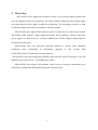
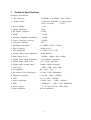
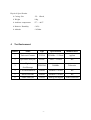
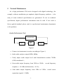
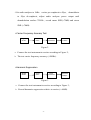
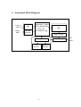
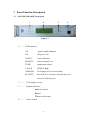
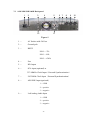
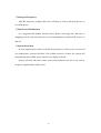
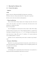
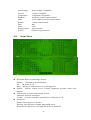
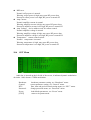
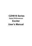
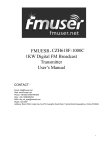
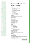
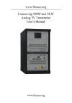
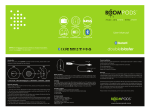
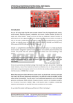
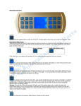
Digital FM Broadcast
Exciter
User’s Manual
Please notice this:
1. Read Safety notice first.
2. A 50Ω dummy load or antenna and cable must be connected before
turning power on , Avoid water going into connecters and cable.
3. Please read System Control Logic section to fully understand how the
system works.
4. Please read Power On Sequence.
-2-
Contents
1 Safety Notice……………………………………………………....4
2 Overview ………………………………………………………….5
3 Technical Specifications…………………………………………..6
4 Test Instrument………………………………………………….....7
5 Test And Maintenance…………………………………………….8
6 Functional Block Diagram……………………………………….10
7 Panel Function Description………………………………….11
8 Power On sequence………………………………………………14
9 System Control Logic....................................................................15
10 Direction For Software Use………………………………..…..17
11 Failures Check…………………………………………………...26
-3-
1 Safety Notice
1.1
Please read the following safety points, in order to avoid the accidents and prevent the
connecting machines to be broken.
1.2
Only the qualified maintenance workers can operate the service.
1.3
revent
the
fire
the
injury
.
.
. P.
.
.
.
.
.
..
.
..
.
.
.and
.
.
..
.
.bodily
...
.
.
..
.
.
.
.
.
a. Use the proper wire. If not, it will cause the fire and the bodily injury;
b. Ensure the machine connect the ground. Please confirm whether the machine has
connected the ground, through the wire and the lead, to prevent the electric shock.
c. Use the proper fuse. Please use the stipulated type and rating fuse.
d. Provide good ventilation. This machine adopts the natural convective radiation. Fix
it correctly to keep it radiating well.
1.4
don’t
repair
yourself
when
it’s
down.
.
.
. Please
.
.
.
.
.
..
..
.
.disassemble
.
.
.
.
.
.
...
.
.and
.
.
..
.
.
.
.
.by
.
..
..
.
.
.
.
..
.
.
..
.
.
.broken
.
.
..
.
..
...
.Please send
to the professional service department to solve the problems.
CAUTION:Please don’t assemble the machine in the moist environment;
Please don’t assemble the machine in the easy exploding
environment;
Please don’t repair by yourself.
1.5
.
.
. If you have any other questions, please connect with us.
:
:
:
-4-
2
Overview
ZHC618F(D) series digital FM broadcast exciter is an excellent digital product that
owns the highest and newest technology. The whole machine adopts the latest digital signal
processing and the direct digital synthesized technology. This advantage provides us with
excellent hearing feature which can match to CD audio quality.
ZHC618F(D) series digital FM broadcast exciter is composed of six parts: main control
and display, audio interface, digital signal processing, power amplifier, remote control and
power supply. It is fitted in the 2U, 19 inches standard case. All the output and input signal is
lead from the back panel.
ZHC618F(D) series has password protected function to protect some important
parameters
from
accidentally
or
incidentally
changing.
It
also
provide
with
LOCK-IN/LOCK-OUT and remote control functions.
ZHC618F(D) exciter has analog and AES/EBU audio interface and SCA interface. It is a full
band FM exciter from 87.00~108.00MHz step 10kHz.
ZHC618F(D) series digital FM broadcast exciter has two frequency synchronous port
with which a synchronous FM broadcasting network can be built.
-5-
3
Technical Specifications
Electrical Specification
Ø
RF Frequency
Ø
Output Power
87.00MHz 108.00MHz Step 10kHz
Continuous adjustable to setting power
Power Accuracy
<±10%
Ø Power stability
<±3%
Ø Output Impedance
50Ω
Ø RF Output connector
N-50K
Ø SFDR
<-70dB
Ø Residual Amplitude Modulation
<-50dB
Ø Carrier Frequency accuracy
±200Hz
Ø Frequency Stability:
1x10⁻⁶
Ø Modulation Deviation
0~120KHz (100% ±75kHz)
Ø Pilot Frequency
19kHz±0.1Hz
Ø Pilot Amplitude
0~12KHz (10% 7.5K)
Ø Analog Audio Input Impedance
600Ω Balance
Ø Audio Input Level
-12dBm~+8dBm, Step 0.1dBm
Ø Digital Audio Input Impedance
110Ω Balance (optional)
Ø Digital Audio Input Level
0.2~10Vpp (optional)
Ø Digital Audio Sample Rate
30kHz~96kHz (optional)
Ø Audio gain
-15dB~+15dB step 0.1dB
Ø Pre-emphasis
0μs、50μs、75μs
Ø LR Channel Level Difference
<0.1dB(100% Modulation)
Ø Frequency Response
<±0.1dB , 30Hz~15000Hz
Ø THD
<0.1%, 30Hz~15000Hz
Ø Stereo Separation
>50dB(type.), 30Hz~15000Hz
Ø SNR
>70dB(type.) , 1kHz 100% Modulation
Ø Power Supply
Ø Heat dissipation
□ AC180V~AC260
Forced ventilation
-6-
47Hz~63Hz
Physical Specification
4
Ø Casing Size
2U、19Inch;
Ø Weight
18kg
Ø Ambient temperature
5℃~+40℃
Ø Relative Humidity
<95%
Ø Altitude
<4500m
Test Instrument
Number
Name
Type
Specification
Manufacturer
1
Universal Counter
53132A
225MHz,12 Word
Agilent
2
Spectrum Analyzer
8560E
30Hz~2.9GHz
HP
TEK2260
200MHz
Tektronix
Digital
3
Oscilloscope
4
FM Demodulation
FMAB
100KHz~5.6GHz
RS
5
Stereo Decoder
FMAB
100KHz~5.6GHz
RS
6
Audio Analyzer
P1DD
Analog and digital
Audio Precision
-7-
5
Test and Maintenance
As a high performance FM exciter designed with digital technology (for
example: software modulation, pre-emphasis, digital frequency synthesis…), the
unity of some technical specifications are guaranteed. To test its technical
specification, higher performance instruments must be used. If test result is
below applied standard, please send it to professional maintenance department
or the producer.
Ø Audio Performance Test
Test Instrument
Digital
Exciter
Power
meter
Power
Attenuator
Figure 1
a.Connect test instrument to exciter according to Figure 1;
b.Make audio analyzer output 400Hz, 0dBm;
c. Finely adjust audio output level until demodulation reaches 75KHz
(100% modulated);
d.Scan audio output frequency from 30Hz to 15kHz, record frequency
response (< ±0.1dB) and distortion (< 0.1%);
d . Scan audio output frequency from 30Hz to 15kHz,record stereo
separation (typical > 50dB);
-8-
f.Set audio analyzer to 1kHz, exciter pre-emphasis to 50μs,
demodulator
to 50μs de-emphasis, adjust audio analyzer power output until
demodulation reaches 75KHz , record mono SNR(>75dB) and stereo
SNR (>70dB).
Ø Carrier Frequency Accuracy Test
Digital
Exciter
Power
meter
Power
Attenuator
Universal
Counter
Figure 2
a.Connect the test instrument to exciter according to Figure 2;
b.The test carrier frequency accuracy (±200Hz).
Ø Harmonic Suppression
Digital
Exciter
Power
meter
Power
Attenuator
Spectrum
Analyzer
Figure 3
a.Connect the text instrument to exciter according to Figure 3;
b.Record harmonic suppression relative to carrier (<-60dB).
-9-
6
Functional Block Diagram
DSP
Analog L
Input R
(Digital Filter、Digital
ADC
Delayer、Pilot generate、
Stereo Code、
Digital
AES/EBU
Input
Interface
DDS
Pre-emphasis etc,)
Band Pass Filter
MCU
Level Adj & Amplify
LCD
RS485/232
Interface
Interface
Figure 4
- 10 -
FM
Output
7 Panel Function Description
7.1
10W/30W/50W/100W Front panel
1
2
3
4
Figure 5
1——
LED Indicator
ON
power supply indicator;
R.F.
RF power out;
AUDIO
stereo indicator;
REMOTE
remote control is on.
TEMP
temperature alarm.
V.S.W.R
VSWR is high.
GENERAL
PA Voltage or PA Current alarm;
RF MUTE
inter-lock in or excessive forward power or
excessive reflect power.
2 ——
LCD display screen
3 ——
Operation button
▲up or increase
●enter
▼down or decrease
4——
Power switch
- 11 -
7.2
10W/30W/50W/100W Back panel
1
2
3
4
12
5
6 7
8
9
11
Figure 6
1—
AC Socket with 5A Fuse
2—
Ground pole
3—
RS232
PIN 2----TX;
PIN 3----RX;
PIN 5----GND;
4—
Fan
5—
RF Output
6—
SCA input (optional) or
327.68MHz Clock Input(External Synchronization)
7—
24.32MHz Clock Input(External Synchronization)
8—
AES/EBU Input (optional)
1----GND
2----positive
3----negative
9—
Left Analog Audio Input
1----GND
2----positive
3----negative
- 12 -
10
10 —
Right Analog Audio Input
1----GND
2----positive
3----negative
11 —
RF Test Port
12 —
RS485
PIN 2----A;
PIN 3----B;
PIN 5----GND;
13--
Interlock out
14--
Interlock in
- 13 -
8 Power On Sequence
8.1
Open the package, check appearance, switch, key button, sockets, and interface
ports on front and rear panels.
8.2
Turn power switch on the “OFF” position and connect power cord to power
source.
8.3
8.4
Connect RF out port to a 50 Ohm dummy load or antenna through a cable.
If it is used in synchronous broadcast network, ensure that 24.32MHz, and
327.68MHz external synchronous clock should be connected
8.5
Turn power on.
8.6
Set RF logical control (see detail in System Logic Control).
8.7
Set RF power.
8.8
Set parameters such as frequency, digital/analog audio input select,
stereo/mono select, audio gain, modulation deviation, pre-emphasis.
8.9 Turn on RF power
- 14 -
9
System Control Logic
☺RF output control
RF output is controlled by three switches: interlock-in (called INTERLOCK), RF
Switch in main menu and period control switch in RTC menu.
Interlock-in: when exciter received an interlock-in signal (logic low signal), it
turns RF power off immediately in any circumstance.
RF Switch: when RF Switch is off, turn off RF power.
When RF Switch is on and Period Control is disabled, turn RF power on to setting
power.
When RF Switch is on and Period Control is enabled, RF power is controlled by
Period Control function (see Period Control).
Period Control: when interlock-in is logic high or float, RF Switch is on and
Period Control is enabled, the control method is as follow:
The system reads current time through RTC and check whether current time is
falling into any of the three periods. If yes; turn on RF power to its setting power. Else
turn off RF power. A period is invalid if start time is greater than or equal to end time.
Current time will never fall into an invalid period. If three periods are all invalid, turn
RF power off for ever.
☺Remote Control
Remote control is set in <SET> menu. When remote control is enabled, remote
LED on front panel is lit and parameters are controlled by remote host and can not be
changed locally except “Remote” flag in <SET> menu. Updated parameters will be
automatically stored in EEPROM.
When remote is disabled, remote host can not control over the exciter but locally
does. Updated parameters will be automatically stored in EEPROM.
RS232 or RS485 are used for remote control. Before enabling remote control,
baud rate and device address should be properly set.
- 15 -
☺Change RF frequency
After RF frequency changed, RF power will drop to 0 first, and then increase to
its setting power.
☺Time Period Modification
It is suggested that disable Period Control before correcting date and time or
changing period’s start and end time to avoid instantaneous undesired RF power on
and off.
☺System Protection
In some urgent cases such as exceeded forward power, reflect power, current and
over temperature, system will reboot. If it is failed successive 5 times, the system will
automatically turns off RF power and just acts display function.
System will also shut down when some main parameter can not be set such as
frequency, digital/analog audio select.
- 16 -
10
Direction For Software Use
10.1
General description
?Buttons
▲▼●
▲: Up or increase, when pressed and held for a longer time, it speeds up.
▼: Down or decrease, when pressed and held for a longer time, it speeds up.
●: enter, used to select menu and enter edited parameter.
?Menu classification
There are three kinds of menus: display menu is display only menu; select menu
used to select sub menu or goes back to its main menu; edit menu used to enter
parameters or configure the system.
How to enter parameter
Just scroll highlight bar to desired edit item and press ● , use ▲ or ▼ to change
parameter and press ● again to save it. Some important parameter or operation may
need further confirmation. In this case, a “Y” or “N” will appear after editing at the
end of the edit line. Use▲ or ▼ to select “Y” (confirm) or “N” (cancel) and press ●
to save updated parameter or cancel it.
Parameter can not be modified locally when remote is enabled except “Remote”
itself.
?Return to Main Menu
When there is no operation (press button) for a long time, system will return to its
main menu automatically with LCD backlight off. Not saved updated parameter will
be replaced with its old value.
?LCD backlight
LCD backlight will be automatically turned off when there is no operation for a
long time and turned on immediately when any key is pressed.
- 17 -
10.2
System Boot up
During the system boot up, company logo is displayed and all LED on front panel
blinks 4 times (power LED is on). After system booting up, it enters to its main menu.
10.3
Main Menu
Audio bar is located on the left side of the screen, it indicates dynamic modulation
deviation. 100% denotes 75KHz modulation.
RF Switch:
FWD Power:
RFL Power:
Frequency:
RF switch, select ON or OFF.
forward power, display only.
reflect power, display only.
RF frequency, display only.
- 18 -
Aud Gain:
[View]
[Status]
[Set]
10.4
left and right audio gain, display only.
parameter data browse menu, see [View] menu.
system running status, see[Status] menu.
parameter setting menu, see [Set] menu.
View Menu
All items in [View] menu are display only.
FWD Power:
RFL Power:
Frequency:
Modu Dev:
Aud Gain:
Aud input:
Pre-emphasis:
Pilot Dev:
forward power.
reflect power.
RF frequency.
modulation deviation.
audio gain.
audio input and modulation mode, see [Set] menu.
pre-emphasis.
pilot deviation.
- 19 -
Amp Voltage:
Current:
Temperature:
Baudrate:
Addr:
Remote:
Date:
Time:
Period Control:
[EXIT]
10.5
l
l
l
l
power voltage of amplifier
current of amplifier.
temperature of amplifier.
baud rate used for remote control.
device address used for remote control.
remote control switch.
date.
time.
period control.
return to its parent menu.
Status Menu
RF output: Refer to control logic section.
Normal:
RF output is in normal status.
Off:
RF power is off.
Drop: RF power can not achieve to its setting power.
System: indicate system errors. Contact equipment provider when error
happens.
Lockin: refer to system control logic section.
Unlocked: system is not locked.
Locked: system is locked by external device, RF power is off.
Fwd Power
Normal: forward power is normal.
Warning: forward power is higher than setting power.
Protected: forward power is too high, RF power is turned off.
- 20 -
l
l
l
l
Rfl Power
Normal: reflect power is normal.
Warning: reflect power is high, may cause RF power drop.
Protected: reflect power is too high, RF power is turned off.
Amp Current
Normal: amplifier current is normal.
Warning: amplifier current is high, may cause RF power drop.
Protected: amplifier current is too high, RF power is turned off.
Amp Voltage: device address used for remote control.
Normal: amplifier voltage is normal.
Warning: amplifier voltage is high, may cause RF power drop.
Protected: amplifier voltage is too high, RF power is turned off.
Temperature: remote control switch.
Normal: temperature is normal.
Warning: temperature is high, may cause RF power drop.
Protected: temperature is too high, RF power is turned off.
10.6
SET Menu
Audio bar is located on the left side of the screen, it indicates dynamic modulation
deviation. 100% denotes 75KHz modulation.
Broadcast:
General:
RTC:
Password:
Preset:
[EXIT]
broadcast parameter setting, see “Broadcast” menu.
system parameter setting, see “General” menu.
date, time and period control setting menu, see “RTC” menu.
change password menu, see “Password” menu.
load default parameters, see “Preset” menu.
return to its parent menu.
- 21 -
► “BROADCAST” Menu
FWD Power:
RFL Power:
Power Set:
Frequency:
Modu Dev:
Aud Gain L:
Aud Gain R:
Audio Input:
Pre-emphasis:
Pilot Dev:
[EXIT]
forward power, display only, used to watch real output power
when adjusting output power percentage.
forward power, display only, used to watch real output power
when adjusting output power percentage.
set the percentage of output power.
set RF frequency.
set modulation deviation.
set left audio gain.
set right audio gain.
D/Mono L: mono modulation, audio from left digital channel.
D/Mono R: mono modulation, audio from right digital channel.
D/Ster LR: stereo modulation, audio from digital channel.
A/Mono L: mono modulation, audio from left analog channel.
A/Mono R: mono modulation, audio from right analog channel.
A/Ster LR: stereo modulation, audio from analog channel.
select pre-emphasis.
set pilot deviation.
return to its parent menu.
- 22 -
► “GERNERAL” Menu
Baud Rate:
Address:
Remote:
[EXIT]
select baud rate for remote control.
set device address for remote control.
enable or disable remote control.
return to its parent menu.
►“RTC” Menu
Date:
Time:
Period Control:
ON Period1:
ON Period2:
ON Period3:
Set or display date.
set or display time.
enable or disable period control.
set first period.
set second period.
set third period.
[EXIT]
return to its parent menu.
- 23 -
►“PRESET” Menu
[Preset] menu is used to load default parameters. Make sure that some
parameters may need to be adjusted after Preset according to your broadcasting
requirement.
Select [Sure] to load default parameters. Select [cancel]to return to Main menu.
Preset default parameters
Frequency:
Power Percentage:
Audio Gain:
Audio Input:
Pre-emphasize:
Modulating deviation:
Pilot deviation:
Delay time:
AGC:
Baud rate:
Address:
Remote:
Period Control:
Password:
97.50 MHz
0.0%
0 dB
Digital audio, Stereo modulation.
50 us
75.0 KHz
7.5 KHz
0 us (only in synchronous exciter)
enable
9600 bps
0
OFF
OFF
000000
► “PASSWORD” Menu
- 24 -
Change password: enter new password in “New” edit box, and enter the same new
password again in “Again” box. If two enters are the same, it will display “change
password successful”, else display “Different password, try again!” . Just [EXIT] if
do not want change password. The initial password if “000000”.
Password Control:Enter [Set] and [Preset] menu need password checking when
Password Control is “ON”; there is no password check when Password Control is
“OFF”.
[EXIT]
return to its parent menu.
► PASSWORD CHECK Menu
Check password before entering [Set] and [Preset] menu When Password Checkl is
enabled. Enter password in “Password” first, and then select [Sure]. If correct
password is entered, it will enter to desired menu. Else it will display “Wrong
password, try again”.
Select [Cancel] to give up password enter and return to its previous menu.
The initial password is “000000”, if need a new password, refer to “Password” menu.
- 25 -
11
Failure Check
11.1 Turn on the power supply, if the equipment doesn’t work, it may
l
The fuse is broken: change the fuse;
l
The plug is not inserted tightly or contacted fault: insert the plug tightly;
l
Synchronous clock source is not connected: check the wire to ensure it has been
connected the clock source correctly. (only used in the synchronous cover
network)
11.2 No audio output
l
The source of audio signal is not connected: check the wire to ensure it has been
connected correctly;
l
Choose the wrong source of the signal: please choose the correct source of signal,
digital or analog.
If there is any other problem that can not be solved, please contact with us
- 26 -