1
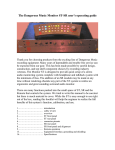
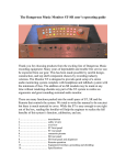
The Dangerous Music Master
Setup and Operation manual
The Dangerous Music mastering transfer console represents the culmination of over 25
years of experience in the design and implementation of custom mastering equipment in
many of the world’s top mastering studios by the designers at DMI. This experience has
been distilled down to a two-rack space unit of exceptional ergonomic and sonic
performance. In conjunction with the Dangerous Music Monitor, the addition of one’s
favorite analog processing equipment and A/D/A converters, the Master makes the setup
of a world-class analog mastering system easier than it has ever been. This manual
explains the features, controls, connections, and suggestions for the operation of this unit.
Introduction
Safety Review
Overview
Rear panel connections
Front panel controls
Internal jumpers
Specifications
1
2
3
4
5
6
7
Safety Review
Certain precautions should be taken when using electrical products. Please observe the safety hints by
reading the manual and obtaining qualified help if necessary to adhere to the precautions. The power
supply must be switched to the proper mains voltage. Please check the red window on the power
supply to verify the correct setting for your location before connecting the mains plug.
1. Always use a properly grounded power supply cord with this product. Please do
not defeat the ground pin on the mains plug. This connection provides earth to the chassis and
signal grounds inside the device for clean and quiet operation. The “Grounding and interface”
section can help the user/installer clear up a buzz problem if one develops.
2. Avoid high temperature operation in equipment racks by providing air
circulation. The number one killer of electronic gear is HEAT. Vented rack panels may look like
wasted space to an interior decorator, but they look like beauty to a technician or equipment
designer! If the front panel is hot, it is roasting inside the box.
3. Avoid areas of high magnetic fields. The steel chassis of Master is designed to shield
the circuits from EMI and RFI (magnetic and radio interference). When installing equipment in
racks, it is prudent to put power amplifiers and large power supplies at least several rack spaces,
if not in a different rack, away from equipment that deals with low level signals. Separation of
high level and low level equipment can pre-empt trouble caused by heat and EMI.
4. Care should be taken to avoid liquid spills around equipment. If a spill occurs,
please shut off the gear and disconnect the mains. A qualified technician should investigate
accidents to prevent further equipment damage or personnel hazards caused by spills.
5. If one is uncomfortable with opening gear and changing jumpers or making
adjustments, please seek qualified help if necessary.
6. If adjustments or jumper changes are required, please disconnect the mains plug
before opening the top. Dropped screws or tools on a live circuit board can manifest themselves
as burn marks and smoked components. While we feel your pain, (been there) subsequent damage
is not covered by the warranty.
Dangerous Music Incorporated reserves the right to change the specifications or modify the designs
of its equipment. Sending in the registration card is our way of keeping in touch with users of our
equipment should this become necessary. Registration information is always kept confidential and never
disclosed to third parties for any reason. Company contact information is on the last page of this manual.
The CE sign on this product signifies the fact that the Master has been tested and
verified to conform to the applicable standards of 89/336/EEC. EN55103-1
(emissions) EN61000-2 (immunity) and EN60065:2002 (safety requirements)
-2-
Overview
The Dangerous Master is easy to set up and use. It is designed to be the platform that
turns a few pieces of analog outboard processing gear, a D/A or analog source, and an
A/D hooked up to an editing computer, into the backbone of a mastering rig.
An analog source is fed to the input where the input gain control lets one precisely set the
level and balance into the insert stack.
Your favorite analog processing gear is hooked up to the inserts. When an insert button is
pressed, that loop is in line. The second loop can work in stereo or “Sum and Minus”
mode. In S&M, one can alter the center pan information of a mix without affecting the
sides and vice versa. For instance, the lead vocal is too bright but the guitars panned to
the sides are dull? The bass in the middle is muddy and the guitars on the sides need
some bottom grunt? Use stereo EQ in S&M to fix both problems! A de-esser can fix
spitting vocals without killing the air on the drum overheads. A limiter with a fast attack
time can tame the snare on an overhead mic pair and let the rest of the kit bloom. These
are the tricks of the big time mastering engineers. We know because we built the
equipment for them! The Width control allows adjustment of the stereo image width. It
works even when Insert 2 is not pressed when S&M is selected. Remember, while S&M
is fun, too much can be a bad thing!
The writer’s favorite suggested processing goes like this:
Insert 1 gets a stereo EQ to set the tone correct for the rest of the stack.
Insert 2 gets a parametric EQ, De-Esser, and Limiter to fix any problem with a mix.
Insert 3 gets a Compressor to control dynamic range for loudness.
The Output Gain control let’s one precisely ‘hit’ the A/D converter at the correct level.
The Input/Output Monitor Selector lets one compare the dry and processed signal and
there is an Input Monitor Offset control so that comparison can be made even after
adding several dB of loudness to the mastered signal. This also allows an easy way to tell
how much apparent loudness has been added to the signal (by matching the apparent
levels and reading the difference on the IMO gain control).
Rear panel connectors
An analog source is fed to the input connectors. There are two sets, selectable by the ‘IN
1-2’ switch on the front panel. This makes it easy to have a D/A normaled to the first
input and the second input wired to a patchbay or tape machine.
The inserts are to include analog processing equipment. It has been found by the authors
after extensive experimentation that 3 insert loops provide the correct number of insert
points verses the minimum number of relays to get the job done. More equipment is
accommodated by ‘ganging’ as explained on the previous page. The insert points can be
run to a patchbay if the added flexibility of patching is needed (to re-route the order of
processing for instance). More connectors and cable may not equal better sound quality.
There are 2 ‘Main outputs’ to feed A/D converters, a tape machine, or patchbay
depending on the user’s preference. The authors use 2 different A/D converters to select
the best one for ‘flavor’ depending on the program material.
The ‘Monitor’ output feeds the Dangerous Music Monitor. The input signal (post Input
level and Input Monitor Offset level controls) or the output signal (post processing) will
be sent to the Monitor depending on the position of the ‘Mon Out’ switch on the front
panel.
The ‘AC IN’ connector goes to the power supply. Please check that the supply is off
before plugging in this cable. Hot plugging will result in burned contacts.
The ‘CHASSIS’ and ‘GROUND’ banana jacks are strapped together at the factory. The
strap may be removed to isolate the chassis and audio grounds. The jacks can be used to
quiet down a troublesome piece of audio equipment (Sontec) with a ground wire if
necessary.
Front Panel controls
The Input Level Controls let the engineer set precisely, the operating level and balance
that will go through the equipment selected by the Insert buttons. The range is 10 dB in
0.5 dB steps.
The top row of buttons under ‘Functions’ select the following:
1. ‘IN 1-2’ selects which input is processed.
2. ‘S&M’ selects whether or not Insert 2 is in Stereo or Middle Sides mode.
3. ‘OUT MON’ selects whether the Monitor Output jacks have the Input or Output
signal sent to the monitor section.
The Input Monitor Offset level control adjusts the level of the Input Monitor. This is very
handy to match the input and output levels to listen to the effect of processing without the
level difference clouding one’s judgment. The engineer can also match input and output
level, look down at the scale, and determine the relative gain obtained from the mastering
process. This control has a scale of -2 to +8dB in 0.5 dB steps.
The S&M width control adjusts the stereo image width when the S&M button is pressed.
Please note that activating S&M without ‘Insert 2’ selected still passes audio through the
matrix.
The Output level control lets one set the final level presented to the A/D converter. The
range is 10dB in 0.5 dB steps.
The level controls are all stepped attenuators for accuracy, repeatability, and highest
sound quality. The attenuators are built with what we feel are the highest quality switches
and resistors available at any cost. It is useful to gently ‘run the switches through’ their
travel every so often to spread the lubricants around inside and wipe the contacts clean.
This helps keep the switches quiet. The use of contact cleaners is not necessary and will
damage the switches by washing the grease out.
Internal Jumpers and Adjustments (please see step 5 on page 2)
The motherboard has input cable shield ground selection jumpers to accommodate
different grounding schemes. It is recommended that all electrical equipment in the studio
is properly grounded by making sure that power cables have 3 pins and that the third pin
is connected to ground. The use of ‘ground lifts’ to clear up a buzz problem is frowned
upon by the international consortium of electrical safety agencies. If a ground noise
problem occurs, it may be cleared up by switching the jumper position on the connector
associated with the piece of gear that is having the buzz problem.
The shield lift headers have 2 posts. A jumper placed over both posts connects the chassis
ground to the cable shield. To lift a shield, pull the jumper off of the posts. It is a good
idea to put the ‘unused’ jumpers on one of the posts to keep from losing the jumper.
Master should not need to be calibrated but in case it does, here is the procedure:
1. Obtain a calibrated oscillator and level measuring device. These should be lab
quality (HP, Tektronix, Neutrik, Audio Precision, etc.)
2. Place the Master on a clean, well lit table with a pad under it to prevent scratches.
3. Remove the top to expose the motherboard for calibration.
4. Hook up the power supply and turn on the unit.
5. Set all controls to unity gain with all Function and Insert switches out.
6. Set the oscillator for +4dBu and plug into Input 1. Feed both channels.
7. Activate ‘Insert 1’ and measure the level coming out of the ‘Send 1’ jacks.
8. Adjust P1 and P2 to measure +4dBu.
9. Deactivate ‘Insert 1’ and adjust P3 and P4 to read +4dBu at ‘Main Output 1’.
10. Adjust P5 and P6 to measure +4dBu at the ‘Monitor Output’ jack.
11. Activate the ‘OUT MON’ function and adjust P7 and P8 to read +4dBu at the
Monitor Output jack.
12. Activate the S&M function and adjust P9 for unity gain at Main Output 1.
13. Pull the right channel’s input. Adjust P10 for minimum signal at the Right output.
The signal should null below -70dBu (-75 typical).
6
Master Specifications
Measurements made with an Audio Precision P1DD at a nominal operating level of
+4dBu
Frequency response
THD+noise
IMD60 4:1
Crosstalk rejection
Headroom
Noise Floor
Power consumption
10Hz- 100kHz within 0.1dB
< 0.0018% band limited to 22kHz
< 0.0025%
> 111 dB
> +27dBu
< -92 dB
40 watts
100-130, 200-250 volts user selectable
Warranty
Free 2 year extended warranty with online registration.
Standard warranty: 90 days parts and labor, subject to inspection.
Does not include damage incurred through abusive operation or
modifications/attempted repair by unauthorized technicians.
For Sales and Information:
USA
Europe
Dangerous Music, Inc.
231 Stevens Road
Edmeston, NY 13335
Dangerous Music, Inc.
Stieleichenweg 55
50999 Köln
Tel: +49 2236 393731
Email: [email protected]
E-mail: [email protected]