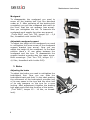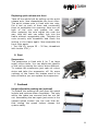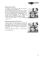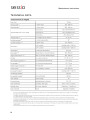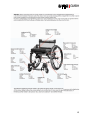
1
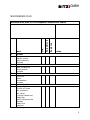
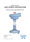
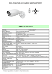
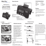
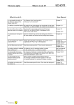
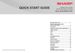
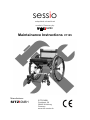
sessio
adaptable wheelchair
made in Germany by
SITZ!GMBH
Maintainance Instructions
Manufacturer:
SITZ!GMBH
SITZ!GMBH
Goethestr. 58
38440 Wolfsburg
Germany
www.sitz-sessio.de
V1105
sessio
Maintainance Instructions
INTRODUCTION
Regular Maintainance will exceed the life cycle and the safety of the
wheelchair. We recommend to cleaning and service like discribed in the
users manual fort he wheelchair routinely. In addition the wheelchair
should be checked and maintained by a sessio wheelchair technician. If
you use the wheelchair very intensively it is recommended to do the
maintainance in shorter time periods.
For repair and maintainance it is only allowed to use original spareparts
released by Sitz!GmbH.
Signs and symbols
Attention! Shows very safety relevant advice. Follow stricly the manual!.
Important! Shows very inportant information.
2
SITZ!GMBH
TABLE OF CONTENTS
INTRODUCTION .............................................................................................................................................2 SIGNS AND SYMBOLS .............................................................................................................. 2 TABLE OF CONTENTS................................................................................................................................3 IMPORTANT SAFETY ADVICE .................................................................................................................4 MAINTAINANCE ADVICE............................................................................................................................4 MAINTAINANCE PLAN ...................................................................................................................................5 ADJUSTMENTS AND REPLACEMENTS...............................................................................................7 1. FRAME ............................................................................................................................ 7 Crossmember for rear wheels ...................................................................................................................................7 2. ATTACHMENTS ................................................................................................................ 7 Anti tilt device ..................................................................................................................................................................7 Mudguard ..........................................................................................................................................................................8 3. BRAKE ............................................................................................................................ 8 Adjusting the brake .......................................................................................................................................................8 Replacing the brakesystem.........................................................................................................................................9 Replacing the braking bolt .........................................................................................................................................9 4. REAR WHEEL................................................................................................................. 10 Replacing the tyre .......................................................................................................................................................10 Quickrelease axle rear ............................................................................................................................................... 10 Handrim...........................................................................................................................................................................10 5. FRONT ROLLERS ........................................................................................................... 10 Replacing the front rollers.......................................................................................................................................10 Replacing quick release axle front .......................................................................................................................11 6. SEAT ............................................................................................................................ 11 Suspension ...................................................................................................................................................................... 11 7. SEATBACK .................................................................................................................... 11 Height adjustable pushing bar (optional) ........................................................................................................11 Suspension ...................................................................................................................................................................... 12 Backframe release.......................................................................................................................................................12 8. FOOTREST .................................................................................................................... 12 Height adjustable footplate .................................................................................................................................... 12 Replacing the footrest................................................................................................................................................ 13 Replacing the handle of the footrest ...................................................................................................................13 TECHNICAL DATA ..................................................................................................................................... 14 3
sessio
Maintainance Instructions
IMPORTANT SAFETY ADVICE
Read the user manual and the maintainance instructions very carfully
before using and maintaining the wheelchair and get familiar with all
functions of the wheelchair prior to any use.
You can downolad all neccessary information on the manufacturers
website www.sitz-sessio.de .
Use only appropriate tools in a appropriate manner.
Wear appropriate cloth and use safety equipment while working on the
wheelchair.
The wheelchair needs to be protected from rolling away and falling down
or tilting over.
Prior to any maintainance the wheelchair needs to be cleaned properly.
MAINTAINANCE ADVICE
After unthightening nuts with threadlock insert use a new nut with
threadlock insert before rethightening in any case.
After unthightening threads with liquid threadlock clean the threads
properly from the threadlock-medium as no particles of this old medium
remain in the thread. If you thighten the thread again use exactly the
threadlock-medium listed in this maintainance instructions.
The maximum life cylce of this wheelchair is 5 years, depending on the
intensity of use and maintainance.
It is recommended to give the wheelchair for check and maintainance to a
sessio wheelchair expert at least once a year. If any mal-funtion or
defects occur on the wheelchair Stopp using it immediately and call your
dealer for assistance and repair.
To find a dealer or sessio technician nearest to you call +495374-9311460
or send mail to [email protected].
Dealers and technicians will be provided with all
neccessary information on demand.
4
SITZ!GMBH
MAINTAINANCE PLAN
Replaced
Adjustments
part
1
frame
frametubes
plastic joints
glue sections
screws
2
attachments
Anti tilt device
Mud guards
screws
3
brakes
function
wear
kinematics
screws
4
rear wheels
Wear of tyres
Profile of tyres
air pressure
air valve
cycling behaviour
bearings
quick release axle
spokes
hand rim
camber
watch 2nd page
OK
Maintainance plan fort he adaptable wheelchair sessio
customer:
notes
5
sessio
5
6
7
8
9
Check done by:
Signature
6
Replaced
Adjustments
OK
part
front rollers
wear
profile
cycling behaviour
bearings
quick release axle
seat
suspension
cushion
seatback
suspension
backframe tubes
adjustable bar
folding mechanism
backframe locking
pushing bar
footrest
Tilting mechanism
locking
footplate
screws
accessories
cane holders
Maintainance Instructions
notes
Date:
SITZ!GMBH
ADJUSTMENTS AND REPLACEMENTS
Attention: Every screwing point on the sessio should only be
unthightened and thightened by an expert trained on and familiar with the
sessio wheelchair. Inadequate modified or rethightened screwings after
service, repair or maintainance on the wheelchair may cause mal-function
or decfects and may cause a safety risk. The inadequate unthightening
and thightening of screwings on the wheelchair is a infringement to the
users manual and causes a immediate loss of all warranties given by the
manufacturer.
The effective thightening torque needs to be within the given range.
Lower torque may cause a unintended unthighening of the screw, higher
torque may cause defects or mal-function.
In any case the threadlock-medium from Henkel´s locktite series
described for every screwing point needs to be used on clean, dry and oiland greasefree threads.
1. Frame
Crossmember for rear wheels
The rear wheels are mounted to the
crossmember, clamped to the mainframe.
These clamps are fixed with four screws.
To adjust or to release the crossmember
unthighten the screws. (Torx T30, torque 7,5 –
8 Nm) Make sure, that the screws are finally
thightened with the right torque.
This screwing doesn´t need a threadlock.
2. Attachments
Anti tilt device
The Anti tilt device is mounted to the rear axle
with a clamp, that is fixed with two screws.
When you attach the anti tilt device, make
sure, that the front end is cliped securely on the
front cross tube of the frame before you
thighten the screws with the right torque (Torx
T30, torque 7,5 – 8 Nm).
This screwing doesn´t need a threadlock.
7
sessio
Mudguard
To disassemble the mudguard you need to
screw off the braking bolt first like discribed
under pt. 3. After screwing off the braking bolt
completely you pull the mudguard taht much to
the front, that the nut appears (see arrow).
Now you unthighten the nut. To assemle the
mudguard work exactly the other way around.
(Tools SW17 and Torx T25, torque 0,6 – 0,8
Nm, threadlock with Loctite 243).
Adjustable mudguard support
To adjust the height of the mudguard you need
to unthighten the lower screw of the mudguard
support bracket (see arrow). Now you can
adjust the height of the mudguard. In the ideal
position there´s 10 mm space between the
mudguard and the tyre. To disassemble the
support bracket unscrew also the upper screw.
Both screwings: (Tool Torx T25, torque 3,5 –
4,0 Nm, threadlock with Loctite 243).
3. Brake
Adjusting the brake
To adjust the brake you need to unthighten the
brakingbolt first. Now you can slide the
brakingbolt back and forth. In the ideal position
the movement of the brakingbolt provides half
of its way space to the tyre and the other half
of its way pressure on the tyre for a save
locking. After adjustment thighten the braking
bolt again and check the function of the brake.
(Tool SW17, torque 15 – 16 Nm, no threadlock).
8
Maintainance Instructions
SITZ!GMBH
Replacing the brakesystem
The complete brakesystem is fixed with two
screws from the bottomand one from the outer
side (see arrows). Unscrew these screws to
take
off
the
whole
brakesystem.
Mounting
the
brakesystem
or
a
new
brakesystem make sure, that the screws get
thightened correctly. Attention: Never try to
unthighten a screw within the brakesystem!
Don´t forget the threadlock.
(Tool Torx T25, torque 3,5 – 4,0 Nm,
threadlock with Loctite 2701).
Replacing the braking bolt
The braking bolt is fixed with a squareheadbolt
on the inner side. The disassemble the braking
bolt simply unthighten the bolt and screw it
fully of. Keep the squareheadbolt in place to
prevent it from falling down. For assembly just
screw the braking bolt onto the squareheadbolt
again. Make sure that the squarehead fits
exactly in its slot. Now adjust the braking bolt
and
thighten
the
bolt
correctly.
(Tool SW17, torque 15 – 16 Nm, no
threadlock).
9
sessio
Maintainance Instructions
4. Rear wheel
Replacing the tyre
Take off the wheel by using the quick release function of the axle. Open
the air valve and make the tyre airless.
Now lift the tyre over the rim with softedged tool to prevent the hose and
the rim from any damage. Tyre and hose can get replaced after that.
Quickrelease axle rear
The quick release axle can be replaced very easily. Pull off the wheel and
than simply pull off the axle from the wheel.
You need to push the button to get it through the bearings.
Handrim
The handrim is fixed with six screws. You need
to unthighten all six screws to get the handrim
off. After replacement make sure that all six
screws are correctly thightened again and check
the proper mounting of the handrim.
Use threadlock Loctite 243 to secure the
screws.
5. Front rollers
Replacing the front rollers
To replace a front roller you need screw off the
nut from the screw completely. Pull out the
screw from the fork, than pull out the roller. If
you assemble the system again make sure, that
the washers left and right from the roller ar
back in place. Use a new nut with solid
threadlock (blue) in any case.
( Tools HX6/SW13, torque 5 – 6 Nm).
10
SITZ!GMBH
Replacing quick release axle front
Take off the whole fork by pulling out the quick
release axle. Now disassemble the front roller.
The quick release axle is fixed with two nuts.
Put a tool on each of them and counterdrill
them to unthighten the screwing. Now turn off
both of the nuts and replace the axle.
After replacing the axle adjust the nuts the
way, that the axle can safely lock into the
frame without recognizable play. Thighten the
nuts correctly with threadlock and check the
locking in the frame again. Now assemble the
front roller again.
( Tool SW 19, torque 25 – 30 Nm, threadlock
with Loctite 2701).
6. Seat
Suspension
The suspension is fixed with 6 (or 7 on large
seats) velcro belts. You can adjust the tension
of the net by placing the velcro strips different.
To replace the suspension just open all velcro
strips and take the suspension off. On some
versions of the frame the brakes need to be
take off before you can replace the suspension.
7. Seatback
Height adjustable pushing bar (optional)
To replace the pushing bar just open the speed
lockers and unscrew them completely. The nuts
within the tubes are secured and can not fall
out. Assembling the bar again just screw in the
opened speed lockers into the nuts that far,
that closing the speed lockers clamps the
system safely.
11
sessio
Maintainance Instructions
Suspension
The tension of the suspension can be adjusted by fastening the velcro
strips in different positions. The suspension can easily be replaced by
opening all of the velcro-strips. Take care, that all strips are fastened
correctly again after replacement.
Backframe release
To replace the cord between the locking bolts
you need to cutt he loops on both sides. Use
new cord and new aluminum sleeves to create
a new loop on each side. Crimp the cord
carefully between the alu sleeve. To soft crimp
may cause a slipping of the cord, to heavy
crimp may cause a damage of the sleeve or the
cord.
To replace the locking bolts you need to take
off the safety washer than you can pull the bolt
out to the outer side. Reassembling the bolt
don´t forget to place the spring back inside and
don´t forget to fasten the safety washer.
Uncorrectly assembled locking bolts may cause
a safety risk.
8. Footrest
Height adjustable footplate
The footplate can easily be adjusted in height.
Just screw off the four screws completely, place
the footplate in the new position and place the
screws again. Take care, that all screws are
placed in the same height. Now tighten the
screws correctly. Check the tightness of the
screws
at
least
once
a
month.
( Tool Torx T30, torque 3,5 – 4,5 Nm, to
threadlock )
12
SITZ!GMBH
Replacing the footrest
To replace the footrest you need to screw off
the footplace like discribed first.
Now screw off the screw that holds the washer
on the sidemembers motion link (see arrow).
Now you can take off both sidemembers to the
inner side. Reassembling the sidemembers use
a little graphite lubricant for the bearing to
prevent from squeaking. Don´t forget to
tighten the screw with the washer correctly.
( Tool Torx T25, torque 5 – 6 Nm, threadlock
Loctite 2701)
Replacing the handle of the footrest
First you need to disassemble the footrest like
discribed. Now you can untighten the screw of
the handle. Than you can pull of the handle.
Reassembling the handle don´t forget to place
the screw with the washer and tighten it
correctly.
( Tool crosstip PZ2, torque 5 – 6 Nm, threadlock Loctite 2701)
13
sessio
TECHNICAL DATA
14
Maintainance Instructions
SITZ!GMBH
15
sessio
SITZ!GMBH
Goethestr. 58
38440 Wolfsburg
Germany
Tel.:
+495361 - 464673
Fax.:
+495361 - 4646749
www.sitz-sessio.de / www.sitzgmbh.de
E-mail: [email protected]
Stand: 04.12.2011
16
Maintainance Instructions