1
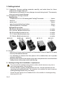
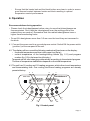
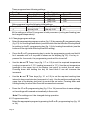
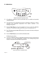
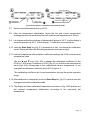
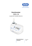
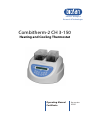
Medical–Biological
Research & Technologies
Combitherm-2 CH 3-150
Heating and Cooling Thermostat
Operating Manual
Certificate
for version
V.2AD
Contents
1. Safety Precautions
2. General Information
3. Getting Started
4. Operation
5. Calibration
6. Specifications
7. Maintenance
8. Warranty and Claims
9. Declaration of Conformity
Page 2
1. Safety Precautions
The following symbols mean:
Caution! Make sure you have fully read and understood the present
Manual before using the equipment. Please pay special
attention to sections marked by this symbol.
Caution! Surfaces can become hot during use.
Caution! To reduce the risk of eye injury during high temperature
operation, use safety spectacles.
GENERAL SAFETY
·
Use only as specified in the Operating Manual provided.
·
The unit should be saved from shocks or falling.
·
After transportation or storage keep the unit under room temperature for 2-3hrs
before connecting to electric circuit.
·
Use only cleaning and decontamination methods recommended by the
manufacturer.
·
Do not make modifications to the design of the unit.
ELECTRICAL SAFETY
·
Connect only to electric circuit with voltage corresponding to that on the serial
number label.
·
Do not plug the unit into an ungrounded power socket, and do not use an
ungrounded extension lead.
·
Ensure that the power switch and the plug are easily accessible during use.
·
If liquid penetrates into the unit, disconnect it from electric circuit and have it
checked by a repair and maintenance technician.
·
Disconnect the unit from electric circuit before moving.
DURING OPERATION
·
Do not check the temperature by touch. Use a thermometer.
Page 3
·
Do not leave the operating unit unattended.
·
Use only thermoresistant glassware.
·
Do not operate the unit in environments with aggressive or explosive chemical
mixtures.
·
Do not use outside laboratory rooms.
·
Do not operate the unit if it is faulty or has been installed incorrectly.
BIOLOGICAL SAFETY
·
It is the user's responsibility to carry out appropriate decontamination if
hazardous material is spilt on or penetrates into the equipment.
Page 4
2. General Information
Combitherm-2 CH 3-150 has been specially designed to thermostabilise materials
at temperatures from -3°C to +150°C according to methods of analysis.
In order to increase performance characteristics and decrease the size of working
area required Combitherm-2 has been designed consisting of 2 independent
replaceable cooling and heating blocks, operated through a common electronic circuit
and encased in a common external body.
The left part of the front keyboard is responsible for setting parameters for cooling
plug-in blocks and the right part - for heating plug-in blocks. Each of them is regulated
independently and can run 16 different programs including temperature and time in
each program.
Peltier technology is used for cooling materials from room temperature to -3°C,
while heating PCB is used for heating (up to +150°C).
Separation of cooling and heating blocks increases durability of the device and
speed of temperature changing after setting a new program.
The unit can be used in biotechnological and biomedical profile laboratories.
Page 5
3. Getting started
3.1. Unpacking. Remove packing materials carefully and retain them for future
shipment or storage of the unit.
Examine the unit carefully for any damage incurred during transit. The warranty
does not cover in-transit damage.
3.2. Complete set. Package contents:
Standard set:
Combitherm-2 CH 3-150 Heating and Cooling Thermostat...................1 piece
block lid..............................................................................................2 pieces
power cord...........................................................................................1 piece
spare fuse (inside the fuse holder)........................................................1 piece
Operating Manual; Certificate ..............................................................1 copy
Optional accessories:
B2-50 block u
with extractor tool........................................................on order
B10-16 block v
with extractor tool......................................................on order
B6-25 block w
with extractor tool.........................................................on order
23-1.5 block x
with extractor tool ......................................................on order
18-12 block y
with extractor tool ........................................................on order
u
B2-50
v
B10-16
w
B6-25
x
23-1.5
y
18-12
3.3. Set up:
- place the unit upon even horizontal non-flammable surface at least 20 cm away
from any flammable materials;
- it is necessary to observe the free space of 40 сm behind the unit to provide
optimum ventilation;
- plug the power cord into the socket on the rear, and position the unit so that there
is easy access to the power switch and the plug.
3.4. Heating/cooling block installation / replacement
Do not touch the heating/cooling block surface which becomes very hot or
cold during operation to avoid burns.
Ensure that the currently installed block isn’t hot. Use the extractor tool for
removing and installing blocks. The extractor tool enables the user to remove
heating/cooling blocks safely and easily.
Screw the tool tightly into a threaded hole in the middle of a heating/cooling
block and lift it out.
Page 6
Ensure that the heater bed and the block bottom are clean in order to ensure
good thermal contact between heater and block resulting in optimal
temperature control performance.
4. Operation
Recommendations during operation
• Please check the tubes/glasses before using, be sure that tubes/glasses are
thermoresistant. Don't heat the tubes/glasses over the melting point of the
material they are made of. Remember that thin-walled tubes/glasses have a
higher thermoconducting factor.
• Do not fill tubes/glasses more than 3-5 mm over the level they are immersed in
the block.
4.1. Connect the power cord to a grounded power socket. Switch ON the power switch
(position I) on the rear panel of the unit.
4.2. The display will turn on and the following readouts will be shown on the display:
– the preset temperature and time in the upper line (Set p.);
– current temperature of the heating/cooling blocks (fig. 1/11) and program
number (fig. 1/5) in the lower line (Actual p.).
Temperature will start changing automatically according to the selected program.
The time of temperature stabilisation depends on the initial temperature.
4.3 The unit has 16 cooling and 16 heating programs, which allow to set temperature
and thermostating time. One cooling and three heating programs are already
preset at factory.
3
5
6
5
4
Combitherm-2
CH 3-150
-3.0 01:00 <
17.5 P14
> 01:00
P5
25
18
11
7
8
1
9
10
2
Fig.1 Control panel
Page 7
These programs have following settings:
Cooling
Temp. °C
-1
Time (Hr :Min)
[P1] 1:00
Heating
Time (Hr :Min)
[P1] 0:30
[P2] 0:07
[P3] 2:00
Temp. °C
80
105
150
Other programs have the following initial settings:
Temp. °C
-1
Time (Hr :Min)
Time (Hr :Min)
[P2-16] 0:00
[P4-16] 0:00
Temp. °C
25
All the settings of all the 16 programs in both processes (cooling and heating) can
be changed independently.
4.4. Changing program settings
·
Select the appropriate program number (fig. 1/5) by pressing PC programming key
(fig.1/3) for a cooling thermoblock (use the buttons on the left side of the keyboard
for setting) or the PH programming key (fig. 1/4) for heating thermoblock (use the
buttons on the right side of the keyboard for setting).
·
Press the PC or PH programming key to enter the programming mode and hold it
for 4 seconds until > or < symbol is shown on the display (fig.1/6). If no key is
pressed for 4 seconds, the programming mode will be turned off.
·
Use the p
and q
Temp. keys (fig. 1/7 or 1/8) to set the required temperature
(cooling increment is 0.1ºC, heating increment is 1ºC). Use the set temperature
readings in the upper line of the display (set point) to control the set value.
Pressing down and holding the key for more than 2 sec will increase the
increment.
·
Use the p
and q
Time keys (fig. 1/1 or 1/2) to set the required working time
interval in hours and minutes (increment is 1 min). Use the set time readings in the
upper line of the display (set point) to control the set value. Pressing down and
holding the key for more than 2 sec will increase the increment.
·
Press the PC or PH programming key (fig. 1/3 or 1/4) second time to save settings
or the settings will be saved automatically in 8 seconds.
Note! The settings can’t be changed during operation.
4.5. Program execution
Select the appropriate program by pressing the PC or PH programming key (fig. 1/3
or 1/4).
Page 8
The heating/cooling process will be started automatically. The temperature will
start changing according to the selected program.
4.6. After thermal stabilisation of the unit (i.e. after the set and the current temperature
become equal), open the heating/cooling block lid, place samples and close the
lid. Use standard tubes/glasses since the block sockets are made precisely in
compliance with their form.
Caution! Do not touch the block surface which becomes very hot or cold during
operation to avoid burns.
4.7. Press the Start Stop key (fig. 1/9 or 1/10) to start the timer. The timer indicator will
start counting down the time interval (with 1 min precision).
4.8. After finishing the program (after the set time elapses) the timer will stop and the
flashing indication will be shown, accompanied by the repetitive sound signal
during eight seconds.
Press the Start Stop key (fig. 1/9 or 1/10) to turn off the signal. Pressing Start
Stop key again will restart the timer.
Caution! Stopping the timer does not stop the heating/temperature maintenance
process.
4.9. The timer can be stopped at any time by pressing the Start Stop key.
4.10. After finishing the operation turn OFF the unit by setting the power switch on the
rear panel to O position and disconnect the power cord from electric circuit.
Page 9
5. Calibration
Combitherm-2
CH 3-150
-3.0 01:00 <
17.5 P14
> 01:00
P5
25
18
Fig.2 Control panel in operation mode
5.1. All calibration operations must be performed only by qualified and specially
trained personnel.
5.2. The instrument is pre-calibrated at the factory (calibrating coefficient is 1.00) for
operation with measured temperature from sensor installed in the
heating/cooling block.
5.3. Hold the Start Stop key (fig. 2/1) pressed for 8 sec to enter the calibration
coefficient. The calibration coefficient will be shown on the display (fig. 3/1).
5.4. Set 1.000 value using the p
and q
keys (fig. 2/2) to restore the factory settings as
shown on fig. 3/1.
5.5. Press the Start Stop key once to exit the calibration mode.
Calibration procedure
5.6. To perform calibration place an independent temperature sensor (measurement
accuracy is 0.5°C) into tubes/glasses installed in the heating/cooling block
sockets. Close the lid if the procedure requires that.
calibration
mode
temperature from
the internal sensor
sct.
1.000
calibration
coefficient
40
40
40
40
temp. with
multiplier coeff.
Fig.3 Control panel in calibration mode
Page 10
set
temp.
current
temp.
set temperature
sct. 40.0
0.974 39.0
calibration
coefficient
40.0
40.0
temp. with
multiplier coeff.
-3
8
1:00
P1
0
P2
40
39
calibrated temperature
Fig.4 Control panel in calibration and operation mode
5.7. Set the required temperature (e.g. 40°C).
5.8. After the temperature stabilization (when the set and current temperature
readings become the same) keep the unit under the set temperature for 30 min.
5.9. Let us assume that the readings of independent sensor is 39 °C, but the display’s
actual temperature is 40 °C. Performing a 1°C calibration is required then.
5.10. Hold the Start Stop key (fig. 2/1) pressed for 8 sec. to activate the calibration
mode. Display will show the following parameters as shown on fig.4.
5.11. Use the Temperature with multiplier coefficient readings (fig. 4 A/2) to set the new
temperature value.
Use the p
and q
keys (Fig. 2/2) to change the calibration coefficient (in the
0.936 to 1.063 range; increment is 0.001) (fig.3/1) so, that the new temperature
value (fig.4 A/2) corresponds to the independent sensor temperature. In our
example the calibration coefficient will be 0.974 (fig.4 A/1).
This calibrating coefficient will correct temperature through the whole operation
range.
5.12. After calibration is completed, press the Start Stop key (fig. 2/1) once to save the
changes and exit the calibration mode.
5.13. The display will show calibrated temperature as shown on fig. 4 B/3 and the unit
will continue temperature stabilization according to the previously set
temperature.
Page 11
6. Specifications
The unit is designed for operation in cold rooms, incubators and closed laboratory rooms at
ambient temperature from +4°C to +40°C and maximum relative humidity 80% for temperatures
up to 31°C decreasing linearly to 50% relative humidity at 40°C.
6.1. Temperature specifications
Heating
·
Temperature setting range ..........................................................+25°C ... +150°C
·
Temperature control range ............................................5°C above RT ... +150°C
·
Temperature accuracy up to105 ºC ............................................................ ±0.5ºC
from 105 ºC to 150 ºC ............................................±1ºC
·
Temperature uniformity up to 105ºC...........................................................±0.2 ºC
·
Time of thermoblock heating from RT(21ºC) to 150 ºC .........not more than12 min
·
Temperature setting resolution ........................................................................1ºC
Cooling
·
Temperature setting range ..............................................................–3°C ... +20°C
·
Temperature control range ................................ 23°C below RT ... 5°C below RT
·
Temperature accuracy ............................................................................... ±0.5ºC
·
Temperature uniformity over the cooling block...........................................±0.2 ºC
·
Time of thermoblock cooling from RT(21ºC) to -3ºC ............not more than 40 min
·
Temperature setting resolution .....................................................................0.1ºC
5.2. General specifications
·
Digital time setting range......................1 min - 99 hrs 59 min (increment is 1 min)
·
Number of programs.....................................................16 (heating) + 16 (cooling)
·
Display ........................................................................................16 x 2 signs LCD
·
Dimensions ................................................................................295x285x220 mm
·
Nominal operating voltage/ power consumption ........230 V, 50 Hz, 420 W (1,8 A)
·
Weight* .........................................................................................................5.6 kg
* Accurate within ±10%.
Page 12
Form of
Description
Catalogue
Optional
socket section
number
accessories *
B2-50
2W
sockets 48 mm, depth 58 mm
BS-010418-AK
B10-16
10 W
sockets 16 mm, depth 56 mm
BS-010418-BK
B6-25
6W
sockets 25 mm, depth 40 mm
BS-010418-CK
B23-1.5
23 sockets for 1.5 ml microtubes,
depth 35 mm
18 W
sockets 12 mm,
depth 58 mm
BS-010418-DK
B18-12
BS-010418-EK
* Other block types are available on the Biosan website at www.biosan.lv.
Biosan is committed to a continuous programe of improvement and reserves the right
to alter design and specifications of the equipment without additional notice.
7. Maintenance
7.1. If the unit requires maintenance electric circuit, disconnect the unit from electric
circuit and contact Biosan or your local Biosan representative.
7.2. All maintenance and repair operations must be performed only by qualified and
specially trained personnel.
7.3. Standard ethanol (75%) or other cleaning agents recommended for cleaning of
laboratory equipment can be used for cleaning and decontamination of the unit.
7.4. Fuse replacement
Remove the power plug from the rear of the
unit. Pull out the fuse holder by applying
leverage in recess (fig. 5/A). Remove the fuse
from the holder. Check and replace with the
correct fuse if necessary (3.15 A for 230 V).
A
Fig. 5 Fuse replacement
Page 13
8. Warranty and Claims
8.1. The Manufacturer guarantees the compliance of unit with the requirements of
Specifications, provided the Customer follows the operation, storage and
transportation instructions.
8.2. The warranted service life of unit from date of delivery to the Customer is 24
months. Contact your local distributor to check availability of extended warranty.
8.3. If any manufacturing defects are discovered by the Customer, an unsatisfactory
equipment claim shall be compiled, certified and sent to the local distributor
address. Please visit www.biosan.lv, Technical support section to obtain the
claim form.
8.4. The following information will be required in the event that warranty or postwarranty service comes necessary. Complete the table below and retain for your
records.
Model
Serial number
Date of sale
Page 14
Combitherm-2, CH 3-150
Heating and Cooling Thermostat
9. Declaration of Conformity
Biosan SIA
Ratsupites 7, build.2, Riga, LV-1067, Latvia
Phone: +371 67426137 Fax: +371 67428101
http://www.biosan.lv
Version 2.02 - December 2012