1
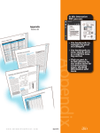
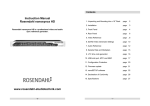
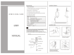
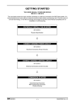
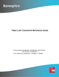
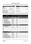
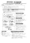
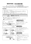
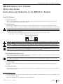
Stellar SR44 Soft Starter Basic Quick-start Guide
SR44 OPTIMIZING SOFT STARTERS
QUICK-START GUIDE:
INSTALLATION AND OPERATION OF THE SR44 SOFT STARTER
Guide To Contents
1 – Mechanical Outlines
Referring to the appropriate size of SR44, mount the SR44 ensuring that correct clearances are maintained for
adequate ventilation and operation of the SR44.
2 – Wiring Diagrams
Referring to the appropriate Wiring Diagram, install the SR44 electrical connections ensuring that the correct
control supply voltage is used and is within the specified operating limits as described on the product specification.
WARNING: Always replace the cover panel on the unit after gaining access to the electrical connections.
The unit requires two AC supplies:
• A three-phase balanced main power supply to provide the source of power for the controlled motor.
• A single-phase, 115/230V, 50/60Hz supply for the internal control circuit.
Control Voltage Selector Switch
115
select
control
voltage
230
WARNING: Ensure that the voltage selector switch position corresponds to the control supply before you apply the control supply
voltage.
WARNING: The SR44 uses semiconductor devices in the main circuit, and is not designed to provide isolation. For this reason,
isolation means must be installed in the supply circuit in accordance with the appropriate wiring and safety regulations.
The Mains Supply and the Control Supply each require protection. Although all SR44 units have electronic overload protection,
the installer should always place fuse protection between the unit and the Mains Supply; NOT between the unit and the motor.
Semiconductor fuses can be supplied for short circuit protection of the semiconductors.
3 – Keypad Operation and Basic Set-up
Refer to this section for familiarization with the keypad controls of the SR44. Use the illustration of the Basic Menu
structure to find SR44 menu items on the display.
We highly recommend that you configure the SR44 by first selecting and setting an application from the “Applications” menu
that is similar to your application. If necessary, you can then ‘fine-tune’ your configuration by changing the settings of other
parameters and menu items.
4 – Set-up Examples
Set-up basic SR44 operating parameters, if necessary, by following one or all of the examples described in this
section.
5 – Product Information
Refer to Product Information for details of Design Standards and Approvals, operating and storage limits, and other
installation instructions.
Further Information
For further information about the SR44 soft starter motor controller, a detailed SR44 user manual is available on the
AutomationDirect website:
http://www.automationdirect.com/static/manuals/index.html.
1st Edition, Revision B
03/13/2015
SR44-QS
QS–1
Stellar SR44 Soft Starter Basic Quick-start Guide
1 – Mechanical Outlines
Size 1: SR44-9 to SR44-146
Size 2: SR44-174 to SR44-370
195.0 [7.68]
All dimensions in mm [in]
Mounting holes & slots suitable for
M6 or 1/4” fittings
Unit weights:
SR44-9 to -44: 7.3 kg [16 lb]
SR44-59 to -146: 8.3 kg [18 lb]
Allow clearances:
15 mm [0.59 in] each side
75 mm [3.0 in] top & bottom
25 mm [0.98 in] front
500.0
[19.69]
340.0
[13.39]
265.0
[10.43]
125.0 [4.92]
150.0 [5.91]
222.0 [8.74]
520.0
[20.47]
362.0 [14.25]
380.0 [14.96]
400.0 [15.75]
415.0 [16.34]
250.0
[9.84]
SR44 size 1: SR44-9 to SR44-146
Mounting Holes/Slots
All dimensions in mm [in]
Mounting centers 250 x 500 [9.8 x 19.7] suitable for M6 fittings
Two “keyholes” at top; two open slots at the bottom
Unit weights: SR44-174 to -202: 16 kg [35 lb]
SR44-242 to -370: 22 kg [49 lb]
Allow clearances:
15 mm [0.59 in] each side
75 mm [3.0 in] top & bottom
25 mm [0.98 in] front
SR44 size 2: SR44-174 to SR44-370
Ventilation for Enclosures
When fitting an SR44 into an electrical enclosure, ventilation must be provided if the heat output of the unit is
greater than the enclosure will dissipate.
If the enclosure cannot dissipate enough heat, use the following formula to determine the fan requirement. An
allowance has been incorporated into the formula so that the figure for “Q” is the air delivery quoted in the fan
supplier’s data.
Q = (4 x Wt) / (tmax – tamb)
• Q = required volume of air (cubic meters per hour; m3/h)
• Wt = heat produced by the unit and all other heat sources within the enclosure (Watts)
• tmax = maximum permissible temperature within the enclosure (40 ºC for a fully rated SR44)
• tamb = temperature of the air entering the enclosure (ºC)
(If you prefer to work in CFM, substitute ºF for ºC. Q will then be in CFM, instead of m3/h.)
An approximation of the heat produced by the SR44 (in Watts) can be made by multiplying the Full Load Line
Current by three. Exact figures for unit Full Load Current are available in the SR44 user manual.
QS–2
SR44-QS
1st Edition, Revision B
03/13/2015
Stellar SR44 Soft Starter Basic Quick-start Guide
2 – Wiring Diagrams
Fig 2.1 Control Circuit Wiring
Fig 2.2 Electronic Control Card
Note: Contactor C3 is required for the 'Operation in
Bypass Power Circuit', and is controlled by the
programmable relay set as a 'Top of Ramp' relay.
Connections shown in the control circuit wiring diagram (Fig 2.1) are
made to the electronic control card terminals as shown in Fig 2.2.
L
Control Supply
115VAC or 230VAC – set voltage switch acordingly
E-STOP
STOP
START
The electronic control card is located underneath the SR44 cover.
N
SR44 Electronic Control Card
C2
D5
J3
C2
ribbon cable
connector J7
SR44 Control Supply Card
X1
Control
Voltage
Switch
115V/230V
Programmable output
SR44 Electronic Control Card
C1
11 K1 14
C2
S1
I/p1
S0
To Current
Transformer
(optional)
J3
1)
2)
3)
4)
Programmable output
Programmable input
Connection for current transformer (CT):
J3 is factory prewired to SR44 internal CT. User-supplied external
CT may be reqired for Bypass operation, depending upon other
settings & parameters. If user-supplied external CT is required,
remove the two pre-connected internal CT wires from J3 and short
them together. Connect the two external CT wires to J3.
Connection polarity is irrelevant.
C3
21 K2 24
Input
J10
22 24 21 12 14 11 S0 S1
To external current
transformer (optional)
X2
J9
J8
Important: Be sure to set the Control Voltage Switch to the proper
control voltage setting before applying voltage to the control circuit.
Power factor CORRECTION CAPACITORS must NOT be positioned on the output of the power circuit.
FUSE SELECTION: Where semiconductor type fuses are required, they should be selected from the table in Section 5.
The IN-LINE configuration shown in Fig 2.3 requires that the Firing Mode (Parameter 6) be set to ‘0’ (Normal Motor).
The IN-DELTA configuration shown in Fig 2.4 requires that the Firing Mode (Parameter 6) be set to ‘1’ (Delta).
[An in-line contactor controlled by the soft starter MUST be used with the In-Delta Firing Mode and motor connections.]
Use the control circuit with one of these power circuits:
The soft starter must be connected to a 3-phase power supply and a 3-phase
load for proper operation. Attempted starts will result in a starter fault if
either the 3-phase power or the 3-phase load is not connected.
Fig 2.4 Power Circuit for
In-Delta Motor Connections (SEE NOTE 4)
Mains Supply (Ve)
Feeder cables
Fig 2.3 Power Circuit for
In-Line Motor Connections
(SEE NOTE 3)
L1
L2
L3
C1 Circuit
Contactor
Feeder cables
Isolation and Protection
Switch-gear
(provided by the customer)
1
L1
2
T1
3
L2
SR44
4
T2
6
T3
Electrical
Ground
1st Edition, Revision B
C1 – Circuit Contactor
X1
1
L1
X2
2
T1
W2 (6)
U1 (1)
3
L2
5
L3
4
T2
6
T3
SR44
Electrical
Ground
03/13/2015
CT* – Current Transformer (optional)
1
L1
V2 (5)
2
T1
V1 (2)
U2 (4)
forward
wiring
connections
shown
Induction
Motor
Feeder cables
OL – if not using CT
W1 (3)
5
L3
Mains
Supply
Isolation and Protection
Switch-gear
(provided by the customer)
C1 Circuit
Contactor
Control
Circuit
NOTE: The “Auto Bypass” Auto Feature (P18/B2;
P86/B2) should be ON for bypass operation.
Using a bypass contactor with Auto Bypass in
the OFF state can cause thyristor faults.
(“ON” is the default “Auto Bypass”setting.)
L1
L2
L3
Isolation and Protection
Switch-gear
(provided by the customer)
Mains
Supply
Fig 2.5 Power Circuit for
Bypass Operation
3
L2
5
L3
4
T2
6
T3
SR44
C3
Bypass
Contactor
Electrical
Ground
In-delta connections for
correct rotation of motor
Term
T1
T2
T3
L1
L2
L3
Fwd
W1(3)
V1(2)
U1(1)
V2(5)
U2(4)
W2(6)
Rev
V1(2)
W1(3)
U1(1)
W2(6)
U2(4)
V2(5)
Induction
Motor
*CT Specifications (User Supplied)
1000/1 ratio; class 1 (1% accuracy)
Crompton M93R-1000/1,
Ohio Semitronics CTY-1000C-1,
Mitchell Instrument Co. 2547ASH-1000-1
or equivalent
SR44-QS
QS–3
Stellar SR44 Soft Starter Basic Quick-start Guide
3 – Keypad Operation and Basic Set-up
WARNING: ALWAYS ENSURE THAT THE KEYPAD CABLE IS PLUGGED IN BEFORE APPLYING POWER TO THE UNIT.
When wired as Fig 2.1, the SR44 display will indicate
start up messages followed by ‘Stopped and ready’.
At this point:
• The SR44 will start the motor when the keypad
‘START/STOP’ key is pressed, but not when the START
switch (shown in Fig.2.1) is closed.
• The SR44 parameters are set to factory default, which
may not be ideal for your required application.
The examples in the next section show how to set up
some of the essential SR44 operating parameters
using the keypad. Once these are understood, other
SR44 settings, as indicated in the programming Menu
Structure below, can be set in a similar manner. (The
corresponding default settings are shown in brackets).
For the full menu structure, refer to the SR44 User
Manual.
Keypad controls
Selects or deselects optimizing (provided keypad control is selected).
Moves the cursor one space from left to right when in data entry mode.
Returns user to previous menu level and
cancels any changes made to settings.
OPTIMISE #
START
STOP
Allows user to move up a menu group
or increment a setting value.
Allows user to move down a menu
group or decrement a setting value.
ENTER
Takes user to next menu level and enters
any changes made to settings.
Starts or stops motor (provided keypad control is selected).
Menu Structure – typical keypad menu
ENTER
Stopped and ready
1:
ENTER
Applications
Auto features
Auto features
Basic
Starter Disabled
1:
To Enable
Basic
Advanced
Advanced
Monitoring
Monitoring
Permanent Store
ENTER
Settings
Default (keypad)
Default Auto
Small Pump
Large Pump
Conveyor
Low Inertia Fan
Hi Inertia Fan
Recip Compressor
Screw Compressor
Rotry Compressor
Crusher
Grinder
Hi Torque Start
Motor Gen Set
aerator
Flywheel / Press
Moulder
Settings
Auto Jog (Off)
Auto Pedestal (Off)
Auto end start (Off)
Auto stop (Off)
Auto end stop (Off)
Auto Bypass (On)
Auto 3MC (On)
Auto Ramp (Off)
Auto All >> Off
P122 Stop Smooth (Off)
Current
Optimise Rate (5)
Optimise + (Off)
Kick Start (Off)
Kick Pedestal (75%)
Kick Time (25 cycles)
Dwell Time (5s)
Low Volts Stop (Off)
Contactor Delay (160 ms)
Trip Sensitivity (1)
Station Number (1)
Firing mode (0) [NOTE 1]
P122 Stop Smooth (5)
Cooling (On)
Cooling Time (–) [NOTE 2]
Temp/Alt Derate (0%)
Line Contactor (On)
Thermistor Trip (Off)
P126 Comms Trip (On)
Disable Starter?
Enable Starter ?
Starting (Keypad)
Start Pedestal (20%)
Start Time (5s)
Stop Pedestal (10%)
Stop Time (0s)
Current Limit (3.5 x Ie)
Protection (Full+ Optimize)
Power
Protection
Current
P27 Peak Start I
P40 Supply Volts
Real PF
P22 Delay Angle
P23 Max Angle
P20 Reference PF
P21 Internal PF
Permanent Store
Password
Password
Inputs
Enter password
Change password
Save parameters
Power on parameters
Default parameters
Outputs
Parameters
Trips
#
#
ENTER
#
1) The “Firing mode” must be set to ‘1’
for the In-Delta configuration.
2) The “Cooling time” is dependent on
the model range, duty rating and
heatsink temperature.
3) The “Rated current” setting is for
reference only, and is not user
adjustable.
Full
Full+ Optimise (Default)
Start+ Bypass
Phase Loss Only
Rated Current (le) [NOTE 3]
Low Current (Off)
Low Amps Level (0.1 x FLC)
Low Amps Time (50 cycles)
C/L Time Out (On)
Current Limit (3.5 x Ie)
Limit Time Out (30s)
Shearpin (On)
Shearpin Level (3.125 x Ie)
Shearpin Time (100cycles)
Overload Level (1.1 x Ie)
Overload Delay (140)
Refer to section 5.3
for details regarding
Current Limit,
Overload Level,
and Overload
Delay settings.
#
Starter Enable/Disable
An additional safety feature has been added so that following certain actions of the starter, it will be disabled.
We strongly recommend that you disable the starter via the Basic Menu before making any changes to parameter values.
Once disabled, the starter remains unable to drive the load until it has been enabled via the Basic Menu, or until the control supply
is removed and reapplied, or until the Down-arrow key is pressed when prompted.
QS–4
SR44-QS
1st Edition, Revision B
03/13/2015
Stellar SR44 Soft Starter Basic Quick-start Guide
4 – Set-up Examples
To keep Menu Item and Parameter setting changes, they must be permanently saved using the ‘Permanent Store’ menu,
as shown below in Example 3.
Ex1: Setting the SR44 for Large Pump Application
2
1
4
� With ‘Starter Disabled’ shown on the display, press
5
ENTER
ENTER
ENTER
ENTER
ENTER key.
Settings
Starter Disabled
Applications
� With ‘Applications’ shown on the top line of the
Default (keypad)
To Enable
1:
Auto features
display, press ENTER.
� With ‘Settings’ shown at the top of the display, press
3
쒃 key until ‘Large pump’ is shown at top of display.
� Press ENTER to select ‘Large pump’. The display will
Large Pump
Send to store?
indicate the parameters changing in short intervals.
Conveyor
#=no Enter=yes
� With the display top line indicating ‘Send to store?’,
#
#
#
press ENTER to save the settings for a large pump to
permanent store. Display will flash the message ‘Storing’ twice to indicate this has been done.
� At any of the above stages, pressing # will return the user to the previous menu. The SR44 will not start until
the control display indicates ‘Stopped and ready’.
Ex2: Setting the SR44 for Remote Starting and Stopping
� With ‘Starter Disabled’ shown on the display, press
1
ENTER key.
ENTER
ENTER
� With ‘Applications’ shown on the top line of the
Starter Disabled
Applications
Auto features
display, press 쒃 key until ‘Basic’ is shown at the top 1: To Enable
of the display.
2
� Press ENTER to select ‘Basic’ menu.
� Press 쒃 key until ‘Starting’ is shown at top of the
Basic
display. Then press ENTER to select starting option
Advanced
menu.
#
#
� With display now indicating ‘Starting’ on top line,
6
6
press ENTER to toggle from ‘Keypad Starting’ to
‘Remote Starting’ as shown on bottom line of display.
� At any of the above stages pressing # will return the user to the previous menu.
3
4
ENTER
ENTER
Starting
Remote starting
5
ENTER
Disable starter
Enable starter
Starting
Starting
Keypad starting
#
6
The SR44 will now start and stop remotely from the START and STOP switches shown in Figure 2.1, but will return
to keypad starting if the control supply is removed from terminals X1 and X2. Alternatively, to return to keypad
starting and stopping, repeat the above procedure and select ‘Keypad Starting’ at step 5.
To keep the remote start/stop setting after removal of the control supply, the settings must be permanently saved
(see Ex3 below).
Ex3: Permanently Saving Parameters Set by User
� With ‘Starter Disabled’ shown on the display, press
ENTER key.
� With ‘Applications’ shown on the top line of the display,
press 쒃 key until ‘Permanent Store’ is shown at top of
display.
� Press ENTER to select ‘Permanent Store’ menu.
� With ‘Save Param’ shown at top of display, press ENTER
to permanently save parameters. Display will flash
twice to indicate that this has been done.
� At any of the above stages pressing # will return the
user to the previous menu.
1st Edition, Revision B
03/13/2015
3
1
ENTER
ENTER
Starter Disabled
1:
To Enable
4
ENTER
Applications
Auto features
2
Permanent store
#
5
Save parameter
Power on param
#
5
SR44-QS
QS–5
Stellar SR44 Soft Starter Basic Quick-start Guide
5 – Product Information
5.1 – Design Standards and Approvals
• CE
• IEC 60947-4-2; EN 60947-4-2 – ‘AC Semiconductor Motor Controllers and Starters’
• RoHS
• UL* –
– Listed to U.S. and Canadian safety standards – E333109
* Options SR44-KPD & SR44-RS485 are not UL approved
5.2 – Basic Ratings
SR44 Basic Ratings
Connector/Terminal
SR44 Range
Rated Frequency
L1, L2, L3
230–460 VAC (-15% +10%)
50/60 Hz (±2 Hz)
X1, X2
115 or 230 VAC (-15% +10%)
S0, S1
12/24 VDC or 115/230 VAC
11,12,14 and 21,22,24
AC1 230V, 3A; 24 VDC, 3A
see semiconductor fuse types table in section 5.4
Form 1
Rated Operational Voltage
Control Supply Voltage (Vs)
Control Input Voltage (Vc)
Output Relays
Rated Operational Current (Ie)
Form Designation
Index Ratings (per IEC 60947-4-2)
SR44 Index Ratings *
Model #
Ie (A)
9 to 105
SR44-9 to SR44-105
SR44-146 to SR44-202
146 to 202
SR44-242 to SR44-370
242 to 370
Standard Operation
AC-53a; X-Tx; F-S
Bypassed Operation
AC-53b; X-Tx; OFF-time
AC-53a: 5-4; 99-10
AC-53a: 3-35; 99-10
AC-53a: 4-6; 99-10
AC-53a: 3-35; 99-10
AC-53a: 4-6; 60-3
AC-53a: 3-35; 60-3
AC-53b: 5-4; 120
AC-53b: 3-35; 120
AC-53b: 4-6; 120
AC-53b: 3-35; 120
AC-53b: 4-6; 420
AC-53b: 3-35; 420
* Index ratings AC-53a and AC-53b are specified by IEC standard # 60947-4-2
In line with the stated IEC starting duties, starters of 242 Amps and above have an enforced off period of seven
minutes set as standard. During this period the display indicates “Stopped. Cooling”, and the starter will not
respond to a start signal.
IEC Index Ratings are comprised of Rated Operational Current (Ie), Utilization Category, Overload Current Profile
(X-Tx), and Duty Cycle (F-S) or OFF-time.
Index Rating Example - Standard Operation (AC-53a Utilization Category per IEC 60947-4-2)
9 to 105 - AC-53a: 3-35; 99-10
Duty Cycle (F-S)
99-10 = 99% duty cycle - 10 cycles/hr
Overload Current Profile (X-Tx)
3-35 = 3 times rated current (Ie) for 35s
Utilization Category
AC-53a = controller semiconductors provide squirrel-cage motor Start, Run, and Stop control
Rated Operational Current (Ie)
9 to 105 = controllers with Rated Operational Currents from 9A to 105A
Index Rating Example - Bypassed Operation (AC53b Utilization Category per IEC 60947-4-2)
9 to 105 - AC-53b: 5-4; 120
OFF-time
120 = 120s minimum OFF-time before restart
Overload Current Profile (X-Tx)
5-4 = 5 times rated current (Ie) for 4s
Utilization Category
AC-53b = controller semiconductors provide squirrel-cage motor Start control only; bypassed for Run and Stop
Rated Operational Current (Ie)
9 to 105 = controllers with Rated Operational Currents from 9A to 105A
QS–6
SR44-QS
1st Edition, Revision B
03/13/2015
Stellar SR44 Soft Starter Basic Quick-start Guide
5.3 – Overload
‘Current limit’, ‘Overload level’ and
‘Overload delay’ settings may be
adjusted to limit overload currents in
accordance with the trip curves shown
here (see Menu Structure in Section 3
for default settings).
Overload start point
1000
Seconds
to trip
100
» For motors with FLCs lower than the
rated current of the SR44, the
‘Overload level’ may be adjusted
using the following formula:
10
Overload Level = Motor FLC x 1.1(A)
1
Delay = 140 (default)
Note:
The overload monitors only one of the
phases, and the ‘Current Limit’ level is
active only during motor starting.
Delay = 80
Delay = 30
0.1
Delay = 10
7.2 x FLC shearpin cutoff
0.01
1
2
3
4
5
6
7
8 9 10
Fault current (Motor Current x N)
IMPORTANT:
We recommend that the control supply
is maintained between starts to ensure
the integrity of the overload, which will
reset on its removal.
5.4 – Safety and Installation
Rated Insulation Voltage (Vi)
Ingress Protection
Pollution Degree
690V
IP20
3
Short Circuit Coordination
Type 1
UL requires Recognized special purpose fuses
(JFHR2) for the protection of semi-conductor
devices, rated 700 VAC, as indicated in Table
5.4, be used to obtain the short circuit ratings
required by UL.
Suitable for use on a circuit capable of delivering
not more than the RMS Symmetrical Amperes
indicated in Table 5.4 at maximum rated
operational voltage, when protected by
Semiconductor Fuse type, Manufactured by
Company and Model Number indicated in Table
5.4. Fuse rated 700 VAC, Amps as indicated in
Table 5.4.
These fuses are for short circuit protection of the
semiconductors and must be mounted externally
by the user between the unit and the mains
supply; not between the unit and the motor.
Table 5.4 – Semiconductor Fuse Types
Model
Name
SR44-9
SR44-16
SR44-23
SR44-30
SR44-44
SR44-59
SR44-72
SR44-85
SR44-105
SR44-146
SR44-174
SR44-202
SR44-242
SR44-300
SR44-370
Ie (A)
Short
Circuit
Withstand
(kA)
9
16
23
30
44
59
72
85
105
146
174
202
242
300
370
5
10
18
UL Recognized JFHR2 Fuses
Bussman
Model #
Mersen (formerly Ferraz)
Amps
Model #
170M3110
6.9 URD 30 D08A 0063
63
170M3112
6.9 URD 30 D08A 0100
100
170M3114
170M3115
6.9 URD 30 D08A 0160
6.9 URD 30 D08A 0200
160
200
170M3116
6.9 URD 30 D08A 0250
250
170M3119
6.9 URD 30 D08A 0400
400
170M3121
6.9 URD 30 D08A 0500
500
170M4114
6.9 URD 31 D08A 0500
500
170M4116
6.9 URD 31 D08A 0630
630
5.5 – Normal Service Conditions
SR44 Normal Service Conditions
Ambient Temperature
Transport and Storage
Altitude
Humidity
1st Edition, Revision B
0 to 40 °C [32 to 104 °F] – Above 40 °C derate linearly by 2% of unit FLC per °C to a maximum of 40% at 60 °C [140 °F]
-25 to +60 °C [-13 to +140] (continuous) – -25 to +75 °C [-13 to +167 °F] (not exceeding 24 hours).
1000m [3281 ft] – Above 1000m derate linearly by 1% of unit FLC per 100m to a maximum altitude of 2000m [6562 ft]
max. 85% non-condensing, not exceeding 50% at 40 °C [104 °F].
03/13/2015
SR44-QS
QS–7
Stellar SR44 Soft Starter Basic Quick-start Guide
5.6 – EMC Emission and Immunity Levels
EMC compliance is in accordance with EN 60947-4-2, which refers to the following basic standards.
SR44 EMC Compliance (in accordance with EN 60947-4-2 *)
Basic Standard
Level
IMMUNITY
Severity Level 3
IEC 61000-4-2
IEC 61000-4-6
IEC 61000-4-3
IEC 61000-4-4
IEC 61000-4-5
6kV contact or 8kV air discharge
140dBuV over 0.15–80 MHz
10V/m over 80–1000 MHz
2kV / 5kHz
2kV line to ground and 1kV line to line
EMISSION
Equipment Class A (Industrial)
EN 55011
Class A
* EN 60947-4-2 is published as a harmonized standard under European Council Directive No.
2004/108/EC in relation to the electromagnetic compatability.
5.7 – Control, Power, and Ground Terminations; Cover & Gland Plate Screws
Control Terminal Specifications
SR44 Control Terminal Specifications
Cable Cross Section
Terminals
Terminal
Type
Wire
Type
X1, X2
S0, S1
11, 12, 14
21, 22, 24
screw clamp
terminals
solid or
(with captive stranded
screws)
AWG
Min
Max
22
Tightening
mm2
Torque
Min
Max
14
0.3
2.5
4.4 lb·in
[0.5 N·m]
Power and Ground Terminal Specifications
SR44 Power and Ground Terminal Specifications
Soft Starter Model
Size 1:
SR44-9 to SR44-146
Size 2:
SR44-174
to SR44-370
Terminals
Power
L1, L2, L3
T1, T2, T3
Ground
PE
L1, L2, L3
T1, T2, T3
Power
Ground
PE
Cable Cross Section * Busbar * Tightening
Torque
AWG
mm2
mm2
Terminal Type **
Conductor Type
M8 metric threaded
studs
M8 metric threaded
stud
M8 metric threaded
studs
M8 metric threaded
stud
Use 75 °C copper (CU)
conductor only,
and the wire shall be fitted with
close eyelet lug
1/0
Use 75 °C copper (CU)
conductor only,
and the wire shall be fitted with
close eyelet lug, or use busbar
2x
250 MCM 2 x 120
50
n/a
106 lb·in
[12 N·m]
20 x 6
* The indicated conductor sizes are the maximum allowed by UL for each chassis size.
The actual conductors used must comply with local wiring regulations.
** Power and Ground terminal studs include M8 nuts, flat washers, and lock washers.
Termination requires ring lugs with hole diameter > 0.3075 in [7.81 mm].
To maintain approvals for cable connections, the Wire Terminals should be UL Listed or Recognized Wire
Connectors and Soldering Lugs, fitted to the wire with special Crimping Tools as indicated by the manufacturer.
The owner, installer, and user are responsible for the correct installation and use of the SR44, and must ensure that only qualified
personnel install the SR44, and that the installation, operation, and maintenance of the unit comply with the relevant Codes of
Practice, Regulations and Statutory Requirements. The Manufacturer or his agent do not assume any liability, expressed or implied,
for any consequence resulting from inappropriate, negligent or incorrect installation, application, use, or adjustment of the product
or circuit design, or from the mismatch of the unit to a motor. To prevent an electrical shock hazard the SR44 must be connected to
a safety ground. The unit is not designed for use in hazardous areas. Use in such an area may invalidate the hazardous area
certification.
Cover & Gland Plate Screw Specifications
Cover and gland plate removal is required for access to electrical terminals.
SR44 Front Cover and Gland Plate Screw Specifications
QS–8
Soft Starter Model
Cover
Screw Type
Tightening
Torque
Size 1:
SR44-9 to SR44-146
Front Cover
Size 2:
SR44-174 to SR44-370
Front Cover
(2) captive M5x20 POZI screws + spring & plain washers;
held captive with M4 nylon 6/6 washers
(4) M5x10 POZI screws & shake-proof washers
(2) captive M5x12 POZI screws + spring & plain washers;
held captive with M4 nylon 6/6 washers
(4) M5x10 POZI screws & shake-proof washers
30 lb·in
[3N·m]
SR44-QS
Gland Plates (upper & lower)
Gland Plates (upper & lower)
1st Edition, Revision B
03/13/2015