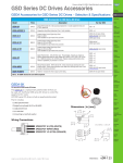
1
™
GSD7 Series DC Drives User Manual
User Manual Number: IH-GSD7-User-M
IronHorse GSD7 DC Drives User Manual – 1st Ed, Rev A – 12/12/2013
Page 1
~ WARNING ~
Thank you for purchasing automation equipment from Automationdirect.com®, doing business as AutomationDirect. We want your new automation equipment to operate safely. Anyone who installs or uses this equipment
should read this publication (and any other relevant publications) before installing or operating the equipment.
To minimize the risk of potential safety problems, you should follow all applicable local and national codes that
regulate the installation and operation of your equipment. These codes vary from area to area and usually change
with time. It is your responsibility to determine which codes should be followed, and to verify that the equipment,
installation, and operation is in compliance with the latest revision of these codes.
At a minimum, you should follow all applicable sections of the National Fire Code, National Electrical Code,
and the codes of the National Electrical Manufacturer’s Association (NEMA). There may be local regulatory or
government offices that can also help determine which codes and standards are necessary for safe installation and
operation.
Equipment damage or serious injury to personnel can result from the failure to follow all applicable codes
and standards. We do not guarantee the products described in this publication are suitable for your particular
application, nor do we assume any responsibility for your product design, installation, or operation.
Our products are not fault-tolerant and are not designed, manufactured or intended for use or resale as on-line
control equipment in hazardous environments requiring fail-safe performance, such as in the operation of
nuclear facilities, aircraft navigation or communication systems, air traffic control, direct life support machines,
or weapons systems, in which the failure of the product could lead directly to death, personal injury, or severe
physical or environmental damage (“High Risk Activities”). AutomationDirect specifically disclaims any
expressed or implied warranty of fitness for High Risk Activities.
For additional warranty and safety information, see the Terms and Conditions section of our catalog. If you have
any questions concerning the installation or operation of this equipment, or if you need additional information,
please call us at 770-844-4200.
This publication is based on information that was available at the time it was printed. At AutomationDirect we
constantly strive to improve our products and services, so we reserve the right to make changes to the products
and/or publications at any time without notice and without any obligation. This publication may also discuss
features that may not be available in certain revisions of the product.
Trademarks
This publication may contain references to products produced and/or offered by other companies. The product
and company names may be trademarked and are the sole property of their respective owners. AutomationDirect
disclaims any proprietary interest in the marks and names of others.
Copyright © 2013 Automationdirect.com® Incorporated
All Rights Reserved
No part of this manual shall be copied, reproduced, or transmitted in any way without the prior, written consent of
Automationdirect.com® Incorporated. AutomationDirect retains the exclusive rights to all information included
in this document.
Page 2
IronHorse GSD7 DC Drives User Manual – 1st Ed, Rev A – 12/12/2013
Contents
WARNING���������������������������������������������������������������������������������������������������������������������������������������������������������������������� 2
Trademarks���������������������������������������������������������������������������������������������������������������������������������������������������������������������� 2
IronHorse GSD7 Series DC Drives General Information����������������������������������������������������������������������������������������������� 4
Selection and Specifications ������������������������������������������������������������������������������������������������������������������������������������������� 6
Dimensions ���������������������������������������������������������������������������������������������������������������������������������������������������������������������� 7
Installation and Wiring���������������������������������������������������������������������������������������������������������������������������������������������������� 8
Start-Up ����������������������������������������������������������������������������������������������������������������������������������������������������������������������� 11
Trim pot Adjustments����������������������������������������������������������������������������������������������������������������������������������������������������� 11
Troubleshooting ����������������������������������������������������������������������������������������������������������������������������������������������������������� 12
GSD7 DC Drives User Manual Overview
Overview of this Publication
The IronHorse GSD7 Series DC Drives User Manual describes the installation, configuration, and
methods of operation of the GSD7 Series DC Drives.
All information contained in this manual is intended to be correct. However, information and data in this
manual are subject to change without notice. AutomationDirect (ADC) makes no warranty of any kind
with regard to this information or data. Further, ADC is not responsible for any omissions or errors or
consequential damage caused by the user of the product. ADC reserves the right to make manufacturing
changes which may not be included in this manual.
Who Should Read This User Manual
This manual contains important information for those who will install, maintain, and/or operate any of the
GSD7 Series DC Drives.
Technical Support
By Telephone: 770-844-4200 (Mon.–Fri., 9:00 a.m.–6:00 p.m. E.T.)
On the Web: www.automationdirect.com
Our technical support group is glad to work with you in answering your questions. If you cannot find
the solution to your particular application, or, if for any reason you need additional technical assistance,
please call Technical Support at 770-844-4200. We are available weekdays from 9:00 a.m. to 6:00 p.m.
Eastern Time.
We also encourage you to visit our web site where you can find technical and non-technical information
about our products and our company. Visit us at www.automationdirect.com.
Special Symbols
When you see the “notepad” icon in the left-hand margin, the paragraph to its
immediate right will be a special note.
When you see the “exclamation mark” icon in the left-hand margin, the paragraph to its immediate right
will be a WARNING. This information could prevent injury, loss of property, or even death (in extreme
cases).
IronHorse GSD7 DC Drives User Manual – 1st Ed, Rev A – 12/12/2013
Page 3
IronHorse GSD7 Series DC Drives General Information
The GSD7 series reversing speed control DC drive is designed to provide rapid reversing, quick and
precise stopping, or rapid cycling for a wide range of DC motor applications. The GSD7 series drives
utilize zero-speed-detect and solid-state-assisted dynamic braking circuits. These circuits eliminate
contact arcing and failed braking problems. The zero-speed-detect circuit also eliminates the motor
problems associated with plug reversing a motor by not reapplying power to the motor until zero speed is
obtained.
• Designed so that upon a power loss condition to the drive or an E-stop condition, the drive will drop
into a dynamic brake condition to safely and quickly bring the motor to a stop and remain there until
power is reapplied and a run condition is recognized.
• Extremely small package size that fits the industry standard footprint for both vertical and horizontal
mounting patterns.
• Designed for DC Permanent Magnet and Shunt Wound motors.
• Incoming AC voltage is converted to adjustable full wave rectified DC voltage to operate the DC motor.
A full wave field voltage is provided for shunt wound motors also.
Carefully check the DC Drive for shipping damage. Report any damage to the
carrier immediately. Do not attempt to operate the drive if visible damage is
evident to either the circuit or to the electronic components.
Standard Features
• Input voltages 120/240VAC @ 50/60Hz; output 0–90/180VDC.
• Adjustable horsepower settings.
• Barrier terminal blocks.
• Full-wave bridge supply.
• 1% speed regulation with armature voltage feedback.
• Adjustable Minimum speed, Maximum speed, IR Compensation, and Current Limit.
• Line voltage compensation.
• 5kΩ speed potentiometer with leads, dial, and knob included.
• 50:1 speed range.
• Transient voltage protection.
• Inhibit circuit permits start & stop without breaking AC lines.
• Shunt field supply provided.
• On-board dynamic braking resistor.
• Automatic dynamic braking on power loss.
• Capable of plugging (reversing motor armature polarity to rapidly change motor direction while it is still
running).
• Available in open-frame chassis.
Page 4
IronHorse GSD7 DC Drives User Manual – 1st Ed, Rev A – 12/12/2013
Control Features
MINIMUM SPEED – Allows adjustment of the motor speed when the speed pot is set at minimum
(CCW). This permits the user to eliminate “Deadband” on the main speed control, permitting zero
calibration. Clockwise rotation of “MIN” trim pot increases speed.
MAX SPEED (Maximum Speed) – Allows adjustment of the motor speed when the speed pot is set at
maximum (CW). This permits the user to eliminate the top end “Deadband”, which will provide full
speed at maximum rotation. Rotation of the “MAX” trim pot in the clockwise direction increases the
maximum motor speed.
ACCEL (Acceleration) – Allows adjustment of the motor acceleration from a minimum of 0.5 seconds to
approximately 8.0 seconds. The deceleration time depends on the ACCEL setting.
IR COMP (Speed Regulation) – Allows for adjustment of the circuitry that controls the speed regulation
of the motor. The circuitry controls armature speed by changing the armature voltage to compensate
for increased or decreased motor loading. Clockwise rotation of the “IR COMP” trim pot will increase
compensation.
CUR LIM (Current Limit) – Provides protection from excessive armature current by limiting the
maximum armature current the drive can provide. This enables adjustment of the maximum torque the
motor can deliver. Torque adjustment (CUR LIM) is preset at 125% of rated motor torque (current) based
on horsepower. Clockwise rotation of the “CUR LIM” trim pot increases the torque (current) the drive
will provide.
ONBOARD DYNAMIC BRAKE RESISTOR – For automatic dynamic braking.
POWER LOSS BRAKE – Upon an E-stop command or a power loss to the drive, the drive will drop into
a dynamic brake condition to safely and quickly bring the motor to a stop and remain stopped until power
is reapplied and a run condition is recognized.
IronHorse GSD7 DC Drives User Manual – 1st Ed, Rev A – 12/12/2013
Page 5
Selection and Specifications
GSD7 Series DC Drives – Selection & Specifications
Model
GSD7-1201CR3
GSD7-1201CR30
GSD7-1205CR3
GSD7-12010CR30
GSD7-2405CR3
1.4
Power Quality Form Factor
120 VAC ±10%
Input Voltage (@50/60Hz)
Motor Rating (hp)
Output Current (continuous)
240 VAC ±10%
0–90 VDC
0–180 VDC
100 VDC (1A max)
200 VDC (1A max)
Output Voltage
Shunt Field Voltage
1/15 – 1/8
1/8 – 1/2
1/8 – 1
500mA–1.2A
(DC)
500mA–5.5A
(DC)
500mA–10A
(DC)
1/25 – 1/4
1/4 – 1
500mA–1.2A 500mA–5.5A
(DC)
(DC)
0.3–3A (DC)
Current Limit (adjustable)
3
1–18A (DC)
30
3
0.3–3A (DC)
30
1–18A (DC)
3
3
30
Metal Oxide Varistor (MOV)
Transient Protection
I.R. Compensation
adjustable
Speed Adjustment
5kΩ 0.5W potentiometer or 0–10VDC isolated input signal
50:1
Speed Range
±1% of base speed
Speed Regulation
Maximum Speed
adjustable from 60% to 110% of base speed
Minimum Speed
linear ramp 0–30% of adjustable maximum speed
Acceleration
0.5 seconds
Deceleration
0.5 seconds
yes
Dynamic Braking
Plugging Capability **
yes
Electrical Connections
barrier-type terminal blocks; 22–14 AWG
Bussman ABC or Littlefuse 314 series ceramic fuses or equivalent
Refer to “Installation and Wiring” section for details.
External Fusing Required
-10 to 45 °C [14 to 113 °F]
Operating Temperature
current limiting
Thermal Protection
can be mounted in any orientation
Mounting Orientation
NOT compatible with any corrosive gases
Corrosive Gases
Agency Approvals
1/4 – 2
500mA–10A
(DC)
200% for 60s
Current Overload Capacity
Weight
GSD7-24010CR30
open frame
Package Configuration
Cycling Rate (cycles/min)
GSD7-2401CR3
1.1 lb [490g]
3.3 lb
[1497g]
3.3 lb
[1497g]
1.1 lb [490g]
CULUS
1.1 lb [490g]
1.1 lb [490g
3.3 lb
[1497g]
Listed (E333109), RoHS
Optional Accessories *
Replacement Potentiometer
GSDA-5K
Digital Potentiometer
GSDA-DP
* For accessories details, please visit www.AutomationDirect.com.
** Plugging is a method of rapidly changing motor direction by reversing motor armature polarity, while the motor is still running.
Page 6
IronHorse GSD7 DC Drives User Manual – 1st Ed, Rev A – 12/12/2013
Dimensions
GSD7-xxx-xCR3 (dimensions = in [mm])
Speed pot
GSD7-xxx-xCR30 (dimensions = in [mm])
Speed pot
Speed pot
Mounting
CUSTOMER’S
MOUNTING BRACKET
DIALPLATE
(2-inch dia)
SPEEDPOT
SPEEDPOT
KNOB
HEX NUT
LOCK
WASHER
IronHorse GSD7 DC Drives User Manual – 1st Ed, Rev A – 12/12/2013
Page 7
Installation and Wiring
Install open-frame drives in an enclosure with a volume at least three
times the volume of the open-frame drive.
Do not mount GSD7-xxx-xCRxx DC drive where ambient temperature is outside the range of -10 to 45 °C (14 to 113 °F).
Size all wires that carry armature or line currents as specified by applicable national, state, and/or local codes. All other wires may be
18AWG or smaller as permitted by the codes.
Separate control wires from the armature and AC lines when routed in
conduit or wire trays.
CAUTION!! Turn power OFF while making wiring connections.
Improper installation or operation of this DC Drive may cause injury to personnel or drive
failure. The drive must be installed in accordance with local, state, and national safety codes.
Make certain that the power supply is disconnected before attempting to service or remove any
components!!! If the power disconnect point is out of sight, lock it in disconnected position
and tag it to prevent unexpected application of power. Only a qualified electrician or service
personnel should perform any electrical troubleshooting or maintenance. At no time should
circuit continuity be checked by shorting terminals with a screwdriver or other metal device.
Before attempting to wire the DC Drive, make sure all power is disconnected. Recheck code
designation to assure proper voltage is present for the DC Drive. Carefully select proper wire
size for current and voltage drop. Limit the voltage drop through the wiring to 5% of the line
voltage at full load
CAUTION!! Do not attempt to perform a hi-pot test across the AC lines with the DC drive in
the circuit. This will result in immediate or long-term damage to the drive.
1) Ensure that the GSD7 drive chassis is properly grounded.
2) The inputs to the speed pot terminals (P1-6, P1-7, P1-8) must not be grounded.
Serious damage may result.
Fusing
External customer-supplied circuit protection is required for all hot AC lines connected to the GSD7
power input terminals AC1/L and AC2/N (P4-1 & P4-2).
Recommended fuse types are Bussman ABC or LittleFuse 314 or equivalent.
(AutomationDirect sells ABC series fuses.)
Fuse Selection *
GSD7-xxx-xxCRxx
Motor HP
Page 8
Fuse @ 120 VAC Input
Fuse @ 240 VAC Input
1/50
2A
–
1/20
2A
1A
1/8
3A
2A
1/4
4A
3A
1/3
6A
3A
1/2
8A
4A
3/4
12A
6A
1.0
15A
8A
1.5
–
12A
2.0
–
15A
* Select fuse type Bussman ABC or Littlefuse 314 series or equivalent.
IronHorse GSD7 DC Drives User Manual – 1st Ed, Rev A – 12/12/2013
Installation and Wiring (continued)
Wiring Terminals
GSD7 Wiring Terminals
Type
Wire Range
Tightening Torque
barrier-type terminal blocks
22–14 AWG
9.0 lb·in [1.0 N·m]
Wiring Terminal Functions
GSD7 Series DC Drives – Terminal Strip Functions
CAUTION: BE SURE DRIVE HOUSING IS PROPERLY GROUNDED.
Number
Purpose
P4-1
(AC1 / L) – For AC systems with a grounded neutral line, connect the Hot (ungrounded) side of your AC line to this
terminal. For systems with two Hot AC lines, connect either of the Hot AC lines to this terminal.
P4-2
(AC2 / N) – For AC systems with a grounded neutral line, connect the Neutral (grounded) side of your AC line to this
terminal. For systems with two Hot AC lines, connect either of the Hot AC lines to this terminal.
P4-3
(A1) – For clockwise rotation of your motor in the Fwd Direction, connect the Plus (+) Armature wire of the motor to this
terminal.
P4-4
(A2) – For counter-clockwise rotation of your motor in the Rev direction, connect the Minus (-) Armature wire of the
motor to this terminal.
P4-5
(REV) – This is the reverse direction input terminal. When connected to the COM terminal, the drive will release
its brake circuit and accelerate to its set point in the reverse direction. When the connection to the COM terminal
is opened, the drive will brake to zero speed. The connection to the COM terminal can be made via a mechanical
switch, a relay contact, or an ungrounded solid-state open-collector type switch. Switching requirements are 5VDC at
less than 1ma.
P4-6
(FWD) – This is the forward direction input terminal. When connected to the COM terminal, the drive will release
its brake circuit and accelerate to its set point in the forward direction. When the connection to the COM terminal
is opened, the drive will brake to zero speed. The connection to the COM terminal can be made via a mechanical
switch, a relay contact, or an ungrounded solid-state open-collector type switch. Switching requirements are 5VDC at
less than 1ma.
P4-7
(COM) – This is the common terminal for the forward and reverse speed/dynamic brake commands.
This terminal should not be grounded or tied to any other terminal.
P4 – Upper Terminal Block Connections
P1 – Lower Terminal Block Connections
P1-4
(-A/-F) – DO NOT use for Permanent Magnet Motor. This supplies -Field voltage for a SHUNT WOUND MOTOR. For
motors with dual voltage field (i.e. 50/100V or 100/200V), make sure highest value is connected. Note: When connecting to this terminal, you will need to use a fork or ring connector placed directly under the screw head.
P1-5
(+F) – DO NOT use for Permanent Magnet Motor. This supplies +Field voltage for a SHUNT WOUND MOTOR. For
motors with dual voltage field (i.e. 50/100V or 100/200V), make sure highest value is connected.
P1-6
(Speed pot Hi) – Connects to high side (white wire) of Speed pot (CW end). This is an internal +12VDC. For startstop applications, the connection between this terminal and Speed pot HI can be opened and closed by a SPST
switch. INPUT MUST NOT BE GROUNDED!
P1-7
(Speed pot Wiper) – Connects to wiper (red wire) of Speed pot (center lead). For Voltage-Follower applications, this
INPUT MUST NOT BE GREATER THAN +12V MAXIMUM AND MUST NOT BE GROUNDED!
P1-8
(Speed pot Lo) – Connects to Low side (orange wire) of 5kΩ Speed pot (CCW end). This input is raised and lowered
by the MIN trim pot (5kΩ). Electronic speed input (voltage follower) may be referenced to Speed pot LO if the MIN trim
pot adjustments are to be active. Otherwise, inputs may be referenced to -ARM, which will bypass the MIN trim pot.
INPUT MUST NOT BE GROUNDED!
IronHorse GSD7 DC Drives User Manual – 1st Ed, Rev A – 12/12/2013
Page 9
Installation and Wiring (continued)
Wiring Diagrams
GSD7-xxx-xxxxx Basic Wiring Diagram
SPEEDPOT
LO
W
-8
-7
-6
-7
FWD
-5
REV
-4
A2
-3
A1
~
N
~
L
-2
P4
W
HI
SPDT
COM
-6
-1
HI
LO
MOTOR
VAC INPUT
VAC INPUT
P1
P1 is underneath P4
P1-4 = -F; P1-5 = +F
For Field Winding of shunt motor;
no connection for permanent magnet motor.
GSD7-xxx-xxxxx Two-Speed Operation
(2) 5kΩ Speedpots
P1
LO
LO
8
W
7
DPDT SWITCH
W
HI
HI
6
GSD7-xxx-xxxxx
GSD7-xxx-xxxxx
P1
(2) 10kΩ Speedpots
LO
LO
8
7
W
SPDT
W
HI
HI
6
GSD7-xxx-xxxxx Inhibit Operation
GSD7-xxx-xxxxx
P1
Page 10
8
LO
7
WIPER
6
SPST
SPEEDPOT
HI
IronHorse GSD7 DC Drives User Manual – 1st Ed, Rev A – 12/12/2013
Start-Up
All power must be OFF before proceeding.
1) Recheck all wiring. Accidental grounds, loose or pinched wires on armature or speed pot wires may
damage the DC drive when power is applied.
2) Check to see that the incoming power is of the correct voltage.
3) Turn the speed pot to zero (fully CCW).
4) Turn power on, close contact from COM (P4-7) to either FWD (P4-6) or REV (P4-5), and advance the
speed pot while observing motor direction of rotation.
Power must be turned off again before step 5 can be accomplished!
5) If the motor rotation is incorrect, turn power off at external disconnect, and reverse the A1 and A2
(P4-3 & P4-4) motor armature connections.
6) Check for satisfactory operation throughout the speed range.
7) If operation is satisfactory, no readjustments are needed.
8) If instability or surging is observed, or if minimum and maximum speed settings need further
adjustments, then refer to the “Trim pot Adjustments” section.”
9) For other problems, consult the “Troubleshooting” section.
Trim pot Adjustments
If the system is unstable after the previous Start-Up procedure, then adjust the trim pots as follows.
These adjustments are maintained, and periodic readjustments are not normally needed. However,
readjustments could be needed if the drive is operated beyond ±10% of the rated line voltage.
GSD7-xxx-xxxxx Trim pot Adjustment
Trim pot
Function
Adjustment
Max
Sets maximum motor speed
when speed pot is set at
maximum (fully CW rotation).
CW rotation of MAX trim pot
increases maximum motor
speed.
1) T
URN DRIVE POWER OFF!!
2) Connect a DC Voltmeter across A1 and A2.
NOTE: Meter must not be grounded!!
3) Set meter voltage range if needed: (90 VDC for 120 VAC; 180VDC for 240 VAC).
4) Turn power ON. Select a direction and set Speed pot at100%.
5) Adjust the MAX trim pot to rated motor armature voltage as shown on meter.
NOTE: A tachometer or strobe may be used in lieu of a meter. Follow above
steps, except adjust MAX trim pot to rated motor base speed indicated by
tachometer or strobe.
Min
Sets minimum motor speed
when speed pot is set at
zero. CW rotation will
increase minimum motor
speed.
1) Select a direction and set Speed pot to zero (fully CCW).
2) Rotate MIN trim pot CW until motor starts to rotate.
3) Slowly rotate MIN trim pot CCW until motor stops. NOTE: If motor rotation is
desired, rotate MIN trim pot CW until desired MIN speed is reached
IR Comp
Provides a means of improving motor speed regulation.
If a slowdown due to load
change is of no concern,
rotate this trim pot fully CCW.
1)
2)
3)
4)
Cur Lim
Limits DC motor armature
current (torque) to prevent
damage to the motor or
drive. The current limit is set
for the rated motor current.
CW rotation of this trim pot
increases the armature current (or torque produced).
1) T
URN DRIVE POWER OFF!
2) Connect a DC ammeter between A1 on motor and A1 on the control. This is in
series with the motor.
NOTE: Meter must not be grounded!!
3) Turn power ON.
4) Select a direction and set Speed pot at the 50% position.
5) Apply friction braking to motor shaft until motor stalls.
6) With motor stalled, set current at 125% of rated motor armature current by adjusting CUR LIM trim pot.
Select a direction and set Speed pot at 50%.
Observe motor speed at no load condition.
Apply full load to motor.
Turn IR COMP trim pot CW until you obtain the same motor speed as the no
load condition.
IronHorse GSD7 DC Drives User Manual – 1st Ed, Rev A – 12/12/2013
Page 11
Troubleshooting
If a newly installed DC Drive will not operate, it is likely that a terminal connection is loose. Check the
terminal connections and ensure that they are secure and correct. If the drive is still inoperative, refer to
the Troubleshooting Table.
Troubleshooting
Problem
Possible Cause(s)
Corrective Action
Motor doesn’t run
1)
2)
3)
4)
1)
2)
3)
4)
Armature output voltage
cannot be adjusted; output is a constant DC level
1) No motor or load connected
2) Speed pot low connection open
1) Low voltage
Replace fuse or reset breaker
Install proper power service
Rotate Speed pot CW to start
Replace motor brushes
1) Ensure that motor or load is connected
to armature terminals
2) Ensure that Speed pot Low wire is connected
3) Worn motor brushes
4) Max speed set incorrectly
1) Ensure that VAC is above 100 VAC for 120V
systems and above 200V for 240V systems
2) Reduce load or increase motor
size or Current Limit setting
3) Replace brushes
4) Consult “Trim pot Adjustments” section
Motor “hunts”
1)
2)
3)
4)
5)
1)
2)
3)
4)
5)
Repeated fuse blowing
1) Low voltage
Motor stalls, or runs very
slowly with speed control
set fully CW
2) Overload condition
2)
3)
4)
5)
Page 12
Blown fuse or circuit breaker
Incorrect or no power
Speed pot set at zero
Worn motor brushes
Motor current less than 150 mA
Too much IR Comp
Motor is in Current Limit
Max trim pot set too high
Motor speed is above rated speed
Overload condition
Worn motor brushes
Defective motor bearings
Defective electrical components
Motor current must be greater than 150 mA (DC)
Consult “Trim pot Adjustments” section
Consult “Trim pot Adjustments” section
Consult “Trim pot Adjustments” section
Reduce speed
1) Ensure that VAC is above 100 VAC for 120V
systems and above 200V for 240V systems
2) Reduce load
3) Replace brushes
4) Replace bearings or motor
5) Contact AutomationDirect “Product
Returns” for replacement
IronHorse GSD7 DC Drives User Manual – 1st Ed, Rev A – 12/12/2013
BLANK
PAGE
IronHorse GSD7 DC Drives User Manual – 1st Ed, Rev A – 12/12/2013
Page 13
BLANK
PAGE
Page 14
IronHorse GSD7 DC Drives User Manual – 1st Ed, Rev A – 12/12/2013
BLANK
PAGE
IronHorse GSD7 DC Drives User Manual – 1st Ed, Rev A – 12/12/2013
Page 15
Literature Number: LT140
Drawing Number: A-5-3905A
Page 16
IronHorse GSD7 DC Drives User Manual – 1st Ed, Rev A – 12/12/2013