1
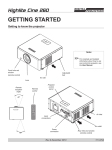
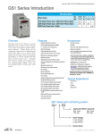
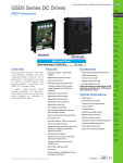
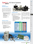
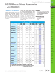
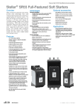
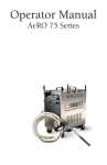
Prices as of April 15, 2015. Check Web site for most current prices.
Stellar® SR44 Full-Featured Soft Starters
Overview
SR44 full-featured solid-state Soft Starters
provide many advantages when used
instead of electromechanical contactors to
control 3-phase AC induction motors. The
SR44 Soft Starters are fully digital, and use
thyristors in all three motor phases for
controlled reduced voltage motor starting
and stopping. SR44s have an Automatic
Application Setup that fully configures the
starter for a specific application with one
entry.
SR44s also have a built-in
“Optimizing” mode that reduces energy
costs when used on lightly loaded and
oversized motors, and external bypass
capability for efficient running at rated
speed.
Features
• 9–370A @ 230–460VAC
• 115 or 230 VAC selectable control voltage
• Full three-phase motor control
• Fully programmable
• Easily and separately adjustable motor start
and stop times
• External bypass capability for run
• Advanced energy-saving Optimizing Mode
improves motor efficiency and power
factor while delivering demanded torque
at low rpm (as compared to across-the-line
control); and prolongs motor life
• Can be connected ‘in-the-delta’, allowing
use of a smaller Soft Starter
• Can be used for motor reversing (with
external contactors)
• Suitable for a wide variety of motor loads
• Keypad: 6 buttons with 2-line, 32-character
display
• Can be used with local or remote control
• Optional Modbus or Remote Keypad
control
• Programmable I/O for remote control:
1 digital input; 2 relay outputs
• Fault record history of last 5 trips
• IP20, panel mount
• Two-year warranty
Standards & Approvals
Advantages
Mechanical Advantages
• Smooth acceleration; reduced mechanical
shock and starting stress
• Extend lifespan of mechanical drive train
components
• Fluid couplings and some clutches can be
eliminated
Electrical Advantages
• Reduced starting currents and spikes
• More motors or larger motors can be
started from lower-capacity power sources
• Allows motors to be started more
frequently
Economic Advantages
• Lower overall costs for new installations
• Reduced maintenance and replacement of
mechanical drive train components
• Reduced starting current lowers demand
charges
• Energy Optimizing mode reduces electrical
power costs
• Automatic Application setup feature
speeds installation by configuring the SR44
for a specific application with one setting.
• CE
• REACH
• RoHS
• UL listed* (E333109)
* Options SR44-KPD & SR44-RS485 are
not UL approved
Optional accessories
• Communication/Modbus card SR44-RS485
• Remote keypad SR44-KPD*
*(requires SR44-RS485)
Applications
• General purpose applications where
traditional across-the-line starting or
wye-delta starting would typically be
appropriate.
SR44-KPD Remote Keypad
SR44 Size 2 Soft Starter
SR44 Size 1 Soft Starter
SR44-RS485
Communication Card
Book 2 (14.1)
eSS-14
Soft Starters
1-800-633-0405
Prices as of April 15, 2015. Check Web site for most current prices.
Stellar® SR44 Full-Featured Soft Starters
Drives
SR44 Soft Starter Technical Specifications
Soft Starters
SR44 Series Full-Featured Soft Starters – Size 1 – 9A-146A*
Model
SR44-9 SR44-16 SR44-23 SR44-30 SR44-44 SR44-59 SR44-72 SR44-85 SR44-105 SR44-146
$735.00 $740.00
$745.00
$800.00
$890.00
$990.00 $1,050.00 $1,210.00 $1,220.00 $1,240.00
Price
9
16
23
30
44
59
72
85
105
146
* Rated Current [class 10(B) trip] (A)
230–460 VAC (-15% +10%) @ 50–60 Hz (±2Hz); 3 phase; (usable on 208V systems down to 196V)
Rated Operational Voltage
Refer to selection table. Starters must be sized according to HP and starting class.
* Motor Rating
4kV
Impulse Withstand Voltage
690 VAC
Insulation Voltage Rating
5 kA
10 kA
Short Circuit Current Rating (type 1)
8VA
10 VA
12 VA
Control Power Consumption
115 VAC (-15% +10%) or 230 VAC (-15% +10%); 1 phase
Control Voltage Range
125
mA
@
115V;
63
mA
@
230V
200 mA @ 115V; 100 mA @ 230V
Control Fuse (external)
12/24
VDC
or
115/230
VAC
Control Input
(2) SPDT; 3A @ 230 VAC; AC11 (electro-magnet control)
Control Relay Outputs
1–255 seconds
Start Time Setting Range
10–60% [% of main power voltage]
Start Voltage Setting Range
0–255 seconds
Stop Time Setting Range
0–40 °C [32–104 °F] – Above 40 °C [104 °F] derate linearly by 2% of unit FLC per °C to a max derate of 40% @ 60 °C [140 °F]
Ambient Operating Temperature
-25–60 °C [-13–140 °F] continuous ; -25–75 °C [-13–167 °F] NOT exceeding 24 hours
Transportation & Storage Temperature
max 85% non-condensing; not exceeding 50% @ 40 °C [104 °F]
Humidity
1000m [3281 ft]; Above 1000m [3281 ft] derate linearly by 1% of unit FLC per 100m to MAX 2000m [6562 ft]
Altitude
IP20
Environmental Rating
16 lb [7.3 kg]
18 lb [8.2 kg]
Shipping Weight
415 x 222 x 195 mm [16.3 x 8.74 x 7.68 in]
Dimensions (HxWxD)
* Refer to Selection Table for deratings by application and overload trip class.
Ambient Operating Temperature
Transportation & Storage Temperature
Humidity
Altitude
Environmental Rating
Shipping Weight
Dimensions (HxWxD)
SR44-174
SR44-202
SR44-242
SR44-300
SR44-370
$1,940.00
$2,025.00
$2,175.00
$2,185.00
$2,695.00
174
202
242
300
370
230–460 VAC (-15% +10%) @ 50–60 Hz (±2Hz); 3 phase; (usable on 208V systems down to 196V)
Refer to selection table. Starters must be sized according to HP and starting class.
690VAC
10 kA
Motion: Servos
and Steppers
Motor Controls
Sensors:
Proximity
Sensors:
Photoelectric
Sensors:
Encoders
Sensors:
Limit Switches
Sensors:
Current
Sensors:
Pressure
Sensors:
Temperature
Sensors:
Level
Sensors:
Flow Switches
Stacklights
Signal
Devices
Process
Pneumatics:
Air Prep
18 kA
18 VA
Pneumatics:
Directional Control
Valves
115 VAC (-15% +10%) or 230 VAC (-15% +10%); 1 phase
200 mA @ 115V; 100 mA @ 230V
Pneumatics:
Cylinders
12/24 VDC or 115/230 VAC
(2) SPDT; 3A @ 230 VAC; AC11 (electro-magnet control)
Pneumatics:
Tubing
1–255 seconds
10–60% [% of main power voltage]
Pneumatics:
Air Fittings
0–255 seconds
0–40 °C [32–104 °F] – Above 40 °C [104 °F] derate linearly by 2% of unit FLC per °C
to a MAX derate of 40% @ 60 °C [140 °F]
-25–60 °C [-13–140 °F] continuous ; -25–75 °C [-13–167 °F] NOT exceeding 24 hours
Appendix
Book 2
max 85% non-condensing; not exceeding 50% @ 40 °C [104 °F]
1000m [3281 ft]; Above 1000m [3281 ft] derate linearly by 1% of unit FLC per 100m to MAX 2000m [6562 ft]
IP20
50 lb [23 kg]
520 x 340 x 265 mm [20.5 x 13.4 x 10.4 in]
* Refer to Selection Table for deratings by application and overload trip class.
Book 2 (14.1)
www.automationdirect.com/soft-starters
Power
Transmission
Relays and
Timers
4kV
40 lb [18 kg]
Motors
Pushbuttons
and Lights
SR44 Series Full-Featured Soft Starters – Size 2 – 174A-370A*
Model
Price
* Rated Current [class 5 starting] (A)
Rated Operational Voltage
* Motor Rating
Impulse Withstand Voltage
Insulation Voltage Rating
Short Circuit Current Rating (type 1)
Control Power Consumption
Control Voltage Range
Control Fuse (external)
Control Input
Control Relay Outputs
Start Time Setting Range
Start Voltage Setting Range
Stop Time Setting Range
Company
Information
Soft Starters
eSS-15
Terms and
Conditions
Prices as of April 15, 2015. Check Web site for most current prices.
Stellar® SR44 Full-Featured Soft Starters
SR44 Soft Starter Optional Accessories
SR44 Series Full-Featured Soft Starters – Optional Accessories
Part Number
SR44-KPD
Name
Price
Description
Can be used to remotely monitor and/or program SR44 Soft Starters. Rated NEMA 4/4X. No external power wiring required.
Works with all SR44 Soft Starters. Includes: Keypad, Cable (3m).
$215.00
NOTE: Optional SR44-RS485 communication card must be installed to use the SR44-KPD remote keypad.
SR44-KPD can control multiple SR44 Soft Starters, but only one at a time.
Can be used to establish RS-485 communication between an SR44 Soft Starter and most Modbus masters. A PLC or PC is
required to demux the data returned from the SR44. (See the User Manual for details and PLC sample ladder programs.)
Plugs directly onto the control board of an SR44. No external power needed. Has both RJ45 connections and screw-type
terminal strip connections; can be used with CAT5 RJ45-terminated Ethernet cable, or with twisted pair shielded wiring.
$95.00 Max # of networked SR44s: 8.
Max network length: 25m [82 ft] for RJ45 connections; 1200m [3937 ft] for RS-485 screw-terminal connections.
Can be used with an SR44-KPD to create an internal RS-485 network between SR44 Soft Starters
(one remote keypad to control multiple SR44s, one at a time).
Works with all SR44 Soft Starters. Includes: Circuit card, Remote/Local selector switch.
Remote Keypad
SR44-RS485* Communication Card *
Communication cables for use with the SR44-RS485 communication card are available in our ZIPLink Wiring Solutions section:
SR44-485HD15-CBL-2 for connection to certain PLCs;
SR44-485RJ45-CBL-2 for connection to certain RS485 networks
SR44 Index Ratings (per IEC 60947-4-2)
SR44 Index Ratings *
Model #
Ie (A)
Standard Operation
AC-53a; X-Tx; F-S
Bypassed Operation
AC-53b; X-Tx; OFF-time
SR44-9 to SR44-105
9 to 105
AC-53a: 5-4; 99-10
AC-53a: 3-35; 99-10
AC-53b: 5-4; 120
AC-53b: 3-35; 120
SR44-146 to SR44-202
146 to 202
AC-53a: 4-6; 99-10
AC-53a: 3-35; 99-10
AC-53b: 4-6; 120
AC-53b: 3-35; 120
SR44-242 to SR44-370
242 to 370
AC-53a: 4-6; 60-3
AC-53a: 3-35; 60-3
AC-53b: 4-6; 420
AC-53b: 3-35; 420
* Index ratings AC-53a and AC-53b are specified by IEC standard # 60947-4-2
In line with the stated IEC starting duties, starters of 242 Amps and above have an enforced off period of seven minutes set as
standard. During this period the display indicates “Stopped. Cooling”, and the starter will not respond to a start signal.
IEC Index Ratings are comprised of Rated Operational Current (Ie), Utilization Category, Overload Current Profile (X-Tx), and Duty
Cycle (F-S) or OFF-time.
Index Rating Example - Standard Operation (AC-53a Utilization Category per IEC 60947-4-2)
9 to 105 - AC-53a: 3-35; 99-10
Duty Cycle (F-S)
99-10 = 99% duty cycle - 10 cycles/hr
Overload Current Profile (X-Tx)
3-35 = 3 times rated current (Ie) for 35s
Utilization Category
AC-53a = controller semiconductors provide squirrel-cage motor Start, Run, and Stop control
Rated Operational Current (Ie)
9 to 105 = controllers with Rated Operational Currents from 9A to 105A
Index Rating Example - Bypassed Operation (AC-53b Utilization Category per IEC 60947-4-2)
9 to 105 - AC-53b: 5-4; 120
OFF-time
120 = 120s minimum OFF-time before restart
Overload Current Profile (X-Tx)
5-4 = 5 times rated current (Ie) for 4s
Utilization Category
AC-53b = controller semiconductors provide squirrel-cage motor Start control only; bypassed for Run and Stop
Rated Operational Current (Ie)
9 to 105 = controllers with Rated Operational Currents from 9A to 105A
Book 2 (14.1)
eSS-16
Soft Starters
1-800-633-0405
Prices as of April 15, 2015. Check Web site for most current prices.
Stellar® SR44 Full-Featured Soft Starters
Company
Information
Drives
SR44 Soft Starter Selection
Soft Starters
Motors
SR44 Soft Starters –
O/L Trip Classes 1
Default
10
Heavy
20
Agitator
10
Air Compressor - Equalized
10B
Air Compressor - Loaded
20
Ball Mill
Centrifuge - e xtended start
needed for sizing
Chiller
20
10B
Conveyor - Unloaded
10B
* Conveyor - Loaded
20
Crusher
30
Escalator
10B
* Fan - Low Inertia < 85A
10
* Fan - High Inertia > 85A
30
Feeder - Screw
10
Grinder
20
Hammer Mill
20
Lathe Machine
10B
Mills - Flour, etc.
20
Mixer - Unloaded
10B
Mixer - Loaded
20
Pelletizer
20
Plastic and Textile Machines
10B
Press - Flywheel
20
* Pump - Centrifugal
* Pump - P ositive Displacement
- Unloaded
Rolling Mill
10B
Saw - Band
10
Saw - Circular
20
Screen - Vibrating
20
Transformer, Voltage Regulator
10B
Tumbler
10
Wood Chipper
30
10
20
Power
Transmission
SR44 Soft Starter Selection Steps
Motion: Servos
and Steppers
1 D
etermine the required trip class based on the motor load and required start
time.
Motor Controls
2 S elect the applicable SR44 part number based on the required Trip Class,
motor HP, and connection type.
Sensors:
Proximity
Sensors:
Photoelectric
SR44 Soft Starters – Selection Table 2
Motor Size
Soft Starter Size
In-Line Connection
In-Delta Connection **
Application Trip Class
HP @ HP @ HP @
HP @ HP @ HP @ Class Class
I (A)
I (A)
Class 20
Class 30
208V* 230V 460V
208V* 230V 460V 10B
10
9
2
3
5
15
2
3
7.5
SR44-9
SR44-16
SR44-23
16
3
5
10
27
3
5
15
SR44-16
SR44-23
SR44-30
23
5
7.5
15
39
5
7.5
25
SR44-23
SR44-30
SR44-44
30
7.5
10
20
51
7.5
10
30
SR44-30
SR44-44
SR44-59
44
10
15
30
76
10
15
50
SR44-44
SR44-59
SR44-72
59
15
20
40
102
15
20
60
SR44-59
SR44-72
SR44-85
72
20
25
50
124
20
25
75
SR44-72
SR44-85 SR44-105
85
25
30
60
147
25
30
100
SR44-85
SR44-105 SR44-146
105
30
40
75
181
30
40
125
SR44-105
SR44-146 SR44-174
146
50
60
100
252
50
60
150
SR44-146
SR44-174 SR44-202
174
60
75
150
301
60
75
250
SR44-174
SR44-202 SR44-242
202
60
75
150
349
60
75
300
SR44-202
SR44-242 SR44-300
242
75
100
200
419
75
100
300
SR44-242
SR44-300 SR44-370
300
100
100
250
519
100
100
350
n/a
SR44-300
SR44-370
370
125
150
300
640
125
150
350
n/a
n/a
SR44-370
* 2 08V applications are UL listed only as low as 196V.
** F or In-Delta connections, all six motor wires must be available for connection, and it is critical to exactly follow the
In-Delta wiring diagram in the SR44 User Manual or Quick-start Guide. (Nine-lead motors CANNOT be connected in the
delta.) The Soft Starter will only sense the Phase Current, which is about 58% of the Line Current.
Sensors:
Encoders
Sensors:
Limit Switches
Sensors:
Current
Sensors:
Pressure
Sensors:
Temperature
Sensors:
Level
Sensors:
Flow Switches
Pushbuttons
and Lights
Stacklights
Signal
Devices
Process
Relays and
Timers
Pneumatics:
Air Prep
Pneumatics:
Directional Control
Valves
* Commonly required applications
Pneumatics:
Cylinders
Pneumatics:
Tubing
Pneumatics:
Air Fittings
Appendix
Book 2
Terms and
Conditions
Book 2 (14.1)
www.automationdirect.com/soft-starters
Soft Starters
eSS-17
Prices as of April 15, 2015. Check Web site for most current prices.
Stellar® SR44 Full-Featured Soft Starters
SR44 Max Overcurrent Protection
Semiconductor Fuse Types for SR44 Soft Starters
UL requires Recognized special
purpose fuses (JFHR2) for the protection of semi-conductor devices
(rated 700 VAC, as indicated in the
Semiconductor Fuse Table) be used
to obtain the short circuit ratings
required by UL.
Model
Name
SR44-9
SR44-16
SR44-23
SR44-30
SR44-44
SR44-59
SR44-72
SR44-85
SR44-105
SR44-146
SR44-174
SR44-202
SR44-242
SR44-300
SR44-370
Suitable for use on a circuit capable
of delivering not more than the indicated RMS Symmetrical Amperes at
maximum rated operational voltage,
when protected by Semiconductor
Fuse type manufactured by Company
and Model Number indicated in the
table.
These fuses are for short circuit
protection of the semiconductors and
must be mounted externally by the
user between the unit and the
incoming main power source; not
between the unit and the motor.
S.C.
Withstand
Ie
(A)
9
UL JFHR2 Fuses for UL Applications *
Mersen
Bussman
(formerly Ferraz) Amps
Model # *
Model # *
Non-UL **
Bussmann Edison
Model
Model Amps
# **
# **
170M3110
6.9 URD 30 D08A 0063
63
FWP-50B
E70S50
50
170M3112
6.9 URD 30 D08A 0100
100
FWP-80B
E70S80
80
44
170M3114
6.9 URD 30 D08A 0160
160
59
170M3115
6.9 URD 30 D08A 0200
200
FWP-125A
E70S125
125
170M3116
6.9 URD 30 D08A 0250
250
FWP-200A
E70S200
200
170M3119
6.9 URD 30 D08A 0400
400
FWP-300A
E70S300
300
170M3121
6.9 URD 30 D08A 0500
500
FWP-400A
E70S400
400
170M4114
6.9 URD 31 D08A 0500
500
FWP-500A
E70S500
500
170M4116
6.9 URD 31 D08A 0630
630
FWP-700A
E70S700
700
16
23
5kA
30
72
85
105
146
10 kA
174
202
242
300
18 kA
370
* Use these fuses with SR44 soft starters in UL applications.
** Use these fuses with SR44 soft starters only in NON-UL applications.
SR44 Internal Overload Trip
Overload start point
‘Current limit’, ‘Overload level’ and
‘Overload delay’ settings may be
adjusted to limit overload currents in
accordance with the trip curves shown
here.
1000
Seconds
to trip
100
(See Menu Structure in User Manual or
Quick-start Guide for default settings.)
10
» For motors with FLCs lower than the
rated current of the SR44, the
‘Overload level’ may be adjusted
using the following formula:
1
Delay = 140 (default)
Overload Level = Motor FLC x 1.1(A)
Delay = 80
Note:
The overload monitors only one of the phases, and
the ‘Current Limit’ level is active only during motor
starting.
IMPORTANT:
We recommend that the control supply is
maintained between starts to ensure the integrity
of the overload, which will reset on control power
removal.
Delay = 30
0.1
Delay = 10
7.2 x FLC shearpin cutoff
0.01
1
2
3
4
5
6
7
8 9 10
Fault current (Motor Current x N)
Book 2 (14.1)
eSS-18
Soft Starters
1-800-633-0405
Prices as of April 15, 2015. Check Web site for most current prices.
Stellar® SR44 Full-Featured Soft Starters
Company
Information
Drives
SR44 Dimensions
Soft Starters
Size 2: SR44-174 to SR44-370
Size 1: SR44-9 to SR44-146
Motors
250.0
[9.84]
Power
Transmission
Motion: Servos
and Steppers
500.0
[19.69]
520.0
[20.47]
362.0 [14.25]
380.0 [14.96]
400.0 [15.75]
415.0 [16.34]
Motor Controls
Sensors:
Proximity
Sensors:
Photoelectric
Sensors:
Encoders
195.0 [7.68]
All dimensions in mm [in]
Mounting holes & slots suitable for
M6 or 1/4” fittings
Unit weights:
SR44-9 to -44: 7.3 kg [16 lb]
SR44-59 to -146: 8.3 kg [18 lb]
Allow clearances:
15 mm [0.59 in] each side
75 mm [3.0 in] top & bottom
25 mm [0.98 in] front
Sensors:
Limit Switches
340.0
[13.39]
265.0
[10.43]
125.0 [4.92]
150.0 [5.91]
222.0 [8.74]
SR44 size 1: SR44-9 to SR44-146
Mounting Holes/Slots
All dimensions in mm [in]
Mounting centers 250 x 500 [9.8 x 19.7] suitable for M6 fittings
Two “keyholes” at top; two open slots at the bottom
Unit weights: SR44-174 to -202: 16 kg [35 lb]
SR44-242 to -370: 22 kg [49 lb]
Allow clearances:
15 mm [0.59 in] each side
75 mm [3.0 in] top & bottom
25 mm [0.98 in] front
SR44 size 2: SR44-174 to SR44-370
Ventilation for Enclosures
Q = (4 x Wt) / (tmax – tamb)
SR44-KPD Mounting Dimensions
Sensors:
Level
Stacklights
4 in (approximate)
Signal
Devices
2.500 in [63.5 mm]
(A)
Process
(A)
Relays and
Timers
Pneumatics:
Air Prep
Four Places
Tapped mounting holes; use #29 drill and 8-32 tap
(Clearance mounting holes; use #19 or 0.166 in drill)
(Use RTV sealant if NEMA 4X rating is required)
1-11/16 in diameter hole;
use 1.25 in conduit knockout
(A)
1.340 in [34.0 mm]
(A)
1.250 in [31.75 mm]
Book 2 (14.1)
Soft Starters
eSS-19
5.5 in (approximate)
SR44-KPD Remote Keypad Mounting Dimensions
Pneumatics:
Directional Control
Valves
(B)
www.automationdirect.com/soft-starters
Sensors:
Temperature
Pushbuttons
and Lights
4.810 in [122.2 mm]
• Q = required volume of air (cubic meters per hour; m3/h)
• Wt = total heat produced by the unit and all other heat sources within the
enclosure (Watts)
• tmax = maximum permissible temperature within the enclosure (40 °C for a
fully rated SR44)
• tamb = temperature of the air entering the enclosure (°C)
(If you prefer to work in CFM, substitute °F for °C. Q will then be in CFM,
instead of m3/h.)
An approximation of the heat produced by the SR44 (in Watts) can be
made by multiplying the Full Load Line Current by three. Exact figures for
unit Full Load Current are available in the SR44 user manual.
Sensors:
Pressure
Sensors:
Flow Switches
When fitting an SR44 into an electrical enclosure, ventilation must be
provided if the heat output of the unit is greater than the enclosure will
dissipate.
If the enclosure cannot dissipate enough heat, use the following formula
to determine the fan requirement. An allowance has been incorporated
into the formula so that the figure for “Q” is the air delivery quoted in the
fan supplier’s data.
Sensors:
Current
Pneumatics:
Cylinders
Pneumatics:
Tubing
Pneumatics:
Air Fittings
Appendix
Book 2
Terms and
Conditions