1
User’s Manual
VER. 1.0
MODEL
TH1912/A
4 1/2 Digit AC MilliVoltmeter
TH1912 Operation manual
Contents
Chapter 1 Introduction.....................................................................................................1
1.1Discription ...........................................................................................................1
1.2Using condition ...................................................................................................2
1.2.1 Power.......................................................................................................2
1.2.2 Environmental temperature and humidity ................................................2
1.3 Dimention and weight .......................................................................................2
1.4 Safety symbols and Precautions.......................................................................2
1.5 Incoming Inspection ..........................................................................................3
1.6 Warranty ...........................................................................................................3
1.7 Limitation of Warranty .....................................................................................3
Chapter 2 Model TH1912 Digital Millivoltmeter introduction............................................5
2.1 Introduction .......................................................................................................5
2.2 Introduction of front panel .................................................................................5
2.2.1 Annunciators on Screen...........................................................................7
2.2.2 Overview of front panel ............................................................................7
2.2.3 Front panel menu reference.....................................................................8
2.2.4 Menu operation introduction ....................................................................9
2.3 Introduction of rear panel ..................................................................................9
2.4 Startinging up preparation and status .............................................................10
2.4.1 Power Line Connection..........................................................................10
2.4.2 Input Terminals....................................................................................... 11
2.4.3 Power-up Sequence .............................................................................. 11
2.4.4 High Energy Circuit Safety Precautions ................................................. 11
2.4.5 Power-on Defaults .................................................................................12
2.4.6 Warm-up time ........................................................................................13
2.5 Display ............................................................................................................13
Chapter 3 Basic Measurements ....................................................................................14
3.1 Preparation ......................................................................................................14
3.2Measuring voltage.............................................................................................14
3.3Select secondary display ..................................................................................15
3.3.1 Operation ...............................................................................................15
3.4 Math operation function ..................................................................................15
3.4.1 Percent ..................................................................................................16
3.4.2 dB calculation ........................................................................................16
3.4.3 dBm calculation .....................................................................................17
Chapter 4 Measurement Options ..................................................................................19
Measurement configuration....................................................................................19
4.1.1
Range...............................................................................................19
4.1.2
Relative ............................................................................................20
4.1.3
Rate..................................................................................................21
I
TH1912 Operation manual
4.2 Trigger operation.............................................................................................21
4.2.1 Trigger procedure.................................................................................21
Reading Hold ..................................................................................................22
4.3 MAX/MIN ........................................................................................................23
4.4 Compare Operations.......................................................................................23
4.4.1 Enabling compare ................................................................................23
4.4.2 Setting Compare Limit Values ..............................................................23
4.5 System Operations .........................................................................................24
4.5.1 Beep.....................................................................................................24
4.5.2 Key Sound ...........................................................................................25
4.5.3 Self-test................................................................................................25
Chapter 5 Remote Operation ........................................................................................26
5.1 RS-232 Interface Operation ............................................................................26
5.1.1 RS-232 Connection................................................................................26
5.1.1RS-232 operation....................................................................................27
(2) Sending and receiving data .......................................................................28
(3) Selecting Baud Rate..................................................................................28
(4) Software Protocol ......................................................................................28
5.2 Data format ......................................................................................................29
Chapter 6 SCPI Command Reference ..........................................................................31
6.1 Command structure .........................................................................................31
6.2 Command Syntax ............................................................................................31
6.1.1 Commands and command parameters: ..............................................31
6.2.2 Short-form Rules....................................................................................33
6.2.3 Basic Rules of Command Structure .......................................................34
6.2.4Multiple Command Rules........................................................................34
6.2.5 Command Path Rules............................................................................34
Command Reference.............................................................................................36
6.3.1 DISPlay subsystem................................................................................36
6.3.2 FUNCtion subsystem .............................................................................36
6.3.3 VOLTage subsystem ..............................................................................37
6.3.4 HOLD subsystem...................................................................................42
6.3.5 TRIGger subsystem ...............................................................................43
6.3.6 FETCH Subsystem ................................................................................44
6.3.7 Common Commands .............................................................................44
Appendix A....................................................................................................................46
Introduction ............................................................................................................46
Appwndix B ...................................................................................................................48
Example of program...............................................................................................48
II
TH1912 Operation manual
Chapter 1 Introduction
Thanks very much for choosing and using our product. If you have any questions
after reviewing this manual, please contact your local representative or call directly to
our application engineers for further consultation.
1.1 Discription
Model TH1912(5Hz — 3MHz)and TH1912A(5Hz — 5MHz) are 4½ Dual VFD
display Dual channel AC Millivoltmeter, which can also be used as power meter and
level meter. The test value and operation value can be displayed. The operation of
intelligent mico processor control technology, good amplifier and A/Dlinearity
cymoscope make the deviation of test voltage lower than 1%. Chip production and
installing craft make the millivoltemeter with the good performance of small volume, light,
high stability, fast test speed, small deviation of frequency reponse.etc.
TH1912/A has wide test range:
·4½ dual reading bright VFD display.
·Voltage range:50μV~300Vrms,500V peak value.
·Power level:-83.8dBm~51.76dBm(0dBm=1mW ,600Ωload).
·Power:0.00417nW~150W(load resistance R=600Ω,load resistance can be set)
·Voltage level dBV range:-86dBV~49.54dBV(0dBv=1V)
·Voltage level dBmV range:-26dBmV~109.5dBmV(0dBmV=1mV)
·Voltage level dBμV range:34dBμV~169.54dBμV(0dBμV=1μV)
·Input resistance:1MΩ, parallel capacitance is about 30pF
·Voltage test probe:when ×10,input resistance is 10MΩ(test accuracy can’t be
guaranteed).
·Max,Min recording function and percent , menu function setting
calculation.Multi-function can combine dual digit VFD display.
·Source impedance setting test power of different signal source and dBm value.
·Float and GND setting,meeting different test demands.
·Auto and manual range switch function.
·Programming language and control interface : Millivoltmeter provides SCPI
programming control language,providing RS-232 C control interface.
.
1
TH1912 Operation manual
1.2 Using condition
1.2.1
Power
Power voltage:220V±10%
Power frequency:50Hz/60Hz±5%
Consumption: ≤ 10VA
1.2.2
Environmental temperature and humidity
Normal working temperature:0℃~40℃,humidity ≤ 90%RH
1.3 Dimension and weight
Dimension(W×H×D):225mm×100mm×315mm
Weight: about 2.5 Kg
1.4 Safety symbols and Precautions
The
symbol on the instrument indicates that user should refer to the operating
instructions located in the manual before performing.
The
symbol on the instrument shows that high voltage may be present on the
terminal(s). Be careful to avoid personal contact with these voltages.
The symbol
on the instruments means earth grounding.
The WARNING heading used in the manual explains high voltage danger that might
result in personal injury or death. Always read the associated information very carefully
before performing the indicated procedure.
The CAUTION heading in the manual reminds user that hazards could damage the
instruments if not according to operating instructions. Such damage may invalidate the
warranty.
2
TH1912 Operation manual
1.5 Incoming Inspection
The TH1912/A was carefully inspected mechanically and electrically before shipment.
After unpacking all items from the shipping carton, please check for any obvious signs of
physical damage that may have occurred during transportation. Report any damage to
the shipping agent immediately. Save the original packing carton for possible future
reshipment. The following items are included with every Model TH1912/A order:
z Model TH1912/A 41/2 Digital AC Milivoltmeter
z Test leads (Model TH26036)
z Power cord
z Two 500mA fuses
z Two 1A fuses
z Operation Manual
z Quality and warranty certificate
z Test report
z Other optional accessories if ordered
Verify that you have received all the items above when you get Milivoltmeter. If anything
is missing, please contact our representative or our sales office.
1.6 Warranty
Tonghui warrants this product to be free from defects in material and workmanship for a
period of 2 years from the date of shipment. During the warranty period, we will, at our
option, either repair or replace any product that proves to be defective.
1.7 Limitation of Warranty
This warranty does not apply to defects resulting from product modification without our
express written consent, or misuse of any product or part. This warranty also does not
apply to fuses, software, or problems arising from normal wear or failure to follow
instructions.
THIS WARRANTY IS IN LIEU OF ALL OTHER WARRANTIES, EXPRESSED OR IMPLIED,
INCLUDING ANY IMPLIED WARRANTY OF MERCHANTABILITY OR FITNESS FOR A
PARTICULAR USE. THE REMEDIES PROVIDED HEREIN ARE BUYER’S SOLE AND
EXCLUSIVE REMEDIES.
NEITHER TONGHUI ELECTRONICS NOR ANY OF ITS EMPLOYEES SHALL BE LIABLE
FOR ANY DIRECT, INDIRECT, SPECIAL, INCIDENTAL OR CONSEQUENTIAL DAMAGES
ARISING OUT OF THE USE OF ITS INSTRUMENTS AND SOFTWARE EVEN IF TONGHUI
ELECTRONICS HAS BEEN ADVISED IN ADVANCE OF THE POSSIBILITY OF SUCH
3
TH1912 Operation manual
DAMAGES. SUCH EXCLUDED DAMAGES SHALL INCLUDE, BUT ARE NOT LIMITED TO:
COSTS OF REMOVAL AND INSTALLATION, LOSSES SUSTAINED AS THE RESULT OF
INJURY TO ANY PERSON, OR DAMAGE TO PROPERTY.
4
TH1912 Operation manual
Chapter 2 Model TH1912 Digital
Millivoltmeter introduction
2.1 Introduction
Model TH1912 4½ Digital AC Millivoltmeter is a kind of fast and accurate AC voltage
test instrument. Compact front panel design can help you get the required test function
quickly, its inherent test platform and system feature can provide an ideal resolution for
your voltage test demand now and I the future.
Convenient test platform feature:
- High brightness VFD Dual display
- Built-in math operation function
- Set signal power of different impedance and dBm relative value.
- Reading hold function by manual setting
- Convenient outline design
Flexible system feature:
-
RS-232 interface
Standard program language SCPI
Reading rate 25 reading/s
COMP compare test with HI/IN/LO signal
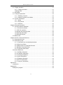
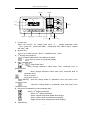
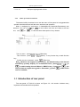
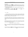
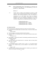
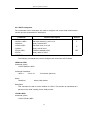
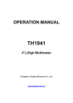
2.2 Introduction of front panel
The front panel of the TH1912 is shown in Figure 1-1. This figure includes some important
abbreviated information that should be reviewed before operating the instrument.
5
TH1912 Operation manual
1 功能键
TH1912
2 数学键
4 1 2 Digit AC Millivoltmeter
CH1
CH2
V
dBm
INPUT
300V RMS
MED
主显
AUTO
CH1
副显
CH2
W
dB
V PEP
dBμ V
dBV
dBmV
%
Comp
Auto
!
CH1
Float
30V RMS
1MΩ || 30pF
300V RMS
Rel
2nd
Hold
Rate
Trig
Menu
Local
Esc
Shift
500V PK
500V PK
输入插座
!
CH2
Float
30V RMS
1MΩ || 30pF
POWER
电源开关 5 量程和方向键 4 菜单操作键 3 速度和
6 Trig/Hold 键
第二显示开关
7 Shift/Local 键
1. Function key
Select test function: AC voltage valid value ( V ) , voltage peak-peak value
(Vp-p),power(W), power level(dBm), voltage level(dBV、dBmV、dBμV),relative
test value(dB).
2. Numeric key
Turn on or off math function(Rel /%,Max/Min/Comp,Hold)
3. 2nd Display and speed key.
Changes reading rate: Fast, Medium and Slow.
→
turns on/ off the 2nd parameter display.
4. Menu operation keys
Shift
→
Open/Close menu
Move through selections within menu level, command level or
parameter level
Move through selections within menu level, command level or
parameter level.
Move up a level.
Move down a level.
(ENTER) Save the change made on “parameter” level, and return to the
“command” level.
Cancel the change made on “parameter” level, and return to the
“command” level.
5. Range and Combination function selecting keys
Select a 2nd display parameter
Select a 2nd display parameter
Select a higher range and disable auto ranging.
Select a lower range and disable auto ranging.
Toggle between auto ranging and manual ranging.
6. Trig/Hold key
6
TH1912 Operation manual
Trigger a measurement from the front panel.
Trig
Shift
→
7. Shift/Local key
Trig
(Local)
Hold a stable reading on the display
Used to access shifted keys.
Cancel RS232C remote control mode and back to the LOCAL mode.
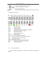
2.2.1 Annunciators on Screen
FAST
Fast reading rate
MED
Medium reading rate
SLOW
Slow reading rate
TRIG
Indicates external trigger (front panel, bus) selected.
HOLD
Reading HOLD function is enabled
AUTO
Auto ranging enabled
REL
Relative operation function
CH1、CH2
channel indication
COMP
Turn on limit compare test function
HI IN LO limit compare high pass, pass and low pass indication
RMT
Milivoltmeter is in remote control mode
AUTO
Auto ranging enabled
MAX MIN Max/Min The indication of Max. and Min. value
ERR
Hardware or remote control error detected
SHIFT
Accessing shifted keys
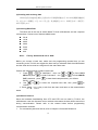
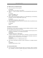
2.2.2
Overview of front panel
The menu of TH1912 is organized by 3 classes (menu, command, )“top-down”tree
structure.
7
TH1912 Operation manual
菜单
命令
参数
Shift
打开菜单
+
左右移动菜单
A: MATH MEU
1: HI LIMIT → 2: COMP LO
Press
B: TRIG MEU
上下移动菜单
C: SYS MEU
1: TRIG MOD → 2: HOLD WIN
1: BEEP STA
to confirm
A:MATH MENU
1: COMP HI → 2:COMP LO → 3:PERC REF → 4:dB REF→ 5:dBm REF8
B:TRIGger MENU
1: TRIG MODE → 2:HOLD WIN → 3:HOLD CNT
C:SYStem MENU
1:BEEP STR → 2:KEY SONG → 3:BAUD RATe → 4:Tx TERM →5:GND STA
2.2.3
Front panel menu reference
A:MATH MENU
1:COMP HI
2:COMP LO
3:PERC REF
4:dB REF
5:dBm Zx
B:TRIG MENU
1:TRIG MODE
2:HOLD WIN
3:HOLD CNT
C:SYS MENU
1:BEEP STR
2:KEY SONG
3:BAUD RAT
4:TX TERM
Set high limit for COMP
Set low limit for COMP
Set reference value for PERCENT
Load or set dB reference value saved in register
Load or set load reference value saved in register
Select trigger mode(IMM/MAN/BUS)
Set the reading hold sensitivity band.
COUNT of readings for reading hold.
Enable or disable the beeper function
Enable or disable the key sound
Select baud rate of RS232C interface
Set ending character in RS232C transmission
8
TH1912 Operation manual
5:GND STA
2.2.4
Set input signal ground or float
Menu operation introduction
The section briefly introducts how to use the menu of front panel. It is suggested that
operator should know and hold the menu structure and operation.
Menu is designed by top-bottom 3 classes(Menus,Commands,Parameters) tree
structure. You can use
one;use
or
·Turn on menu,press
· Turn off menu,press
key.
or
to move menu tree from one class to the next
to view the same-class option of any classes.
+
+
(Menu)key.
(Menu),or any function key or math function
· Confirm a menu command,press
(Enter) key.
Note:TH1912 is set singlely in each channel,the default setting is the channel
selected by primary display. Or in“Parameter”class, press
+
or
to switch setting channel. When in “MENU”class,if you press
,you
can’t be back to a higher menu;and in “Parameter”,if press
,a lower menu
can’t be available.
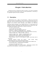
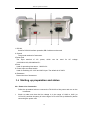
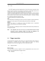
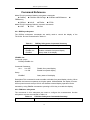
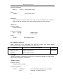
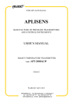
2.3 Introduction of rear panel
The rear panel of TH1912 is shown as Figure 2-2,this section includes many
importance information before operation.
9
TH1912 Operation manual
1
6
2
5
4
3
1. RS-232
Used for RS-232 interface operation,DB-9 cable must be used.
2. Ground
The ground terminal of instrument.
3.Power jack
The input terminal of AC power, which can be used for
110V/220V±10%,50Hz/60Hz±5%。
4.Fuse
Used for protecting instrument,220V/0.5A。
5. Power input converted switch
Used for switching AC 110V/ and 220V input. The default is AC 220V.
6. Platename
Record the No.of instrument.
AC
voltage
2.4 Starting up preparation and status
2.4.1 Power Line Connection
1.
Follow the procedure below to connect the TH1912/A to line power and turn on the
instrument.
Check to make sure that the line voltage is in the range of 198V to 242V (or
110V±10%) and line frequency is in the range of 47.5 to 52.5Hz (or 60Hz±5%) before
connecting the power cord.
10
TH1912 Operation manual
CAUTION: Operating the instrument on an incorrect voltage may cause damage to
the instrument, possibly voiding the warranty.
2.
3.
Before plugging in the power cord, make sure that the front panel power switch is in
the off position.
Connect the female end of the supplied power cord to the AC receptacle on the rear
panel. Connect the other end of the power cord to a grounded AC outlet.
WARNING: The power cord supplied with the Model TH1912/A contains a separate
ground wire for use with grounded outlets. When proper connections
are made, instrument chassis is connected to power line ground
through the ground wire in the power cord. Failure to use a grounded
outlet may result in personal injury or death due to electric shock.
4.
Turn on the instrument by pressing the front panel power switch and get ready for
measuring.
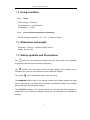
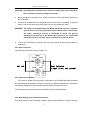
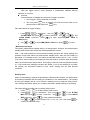
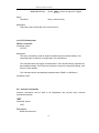
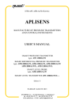
2.4.2 Input Terminals
Input terminal function is shown as Figure 2-3.
Float indicator
(light:float;off:ground)
BNC Jack
2.4.3 Power-up Sequence
On power-up, Model TH1912 performs self-tests on its EPROM and RAM and lights
all segments and annunciators for about 1 second. If a failure is detected, the instrument
momentarily displays an error message and the ERR annunciator turns on.
If the instrument passes self-tests, the firmware revision will be displayed.
2.4.4 High Energy Circuit Safety Precautions
To optimize safety when measuring voltage in high energy distribution circuits, read and
11
TH1912 Operation manual
use the directions in the following warning.
When making measurements in high energy circuits, use test leads and accessories that
meet the following requirements:
Test leads and accessories must be fully insulated.
Only use test leads that can be connected to the circuit (e.g., alligator clips,
spade lugs, etc.) for hands-off measurements.
Do not use test leads or accessories that decrease voltage spacing. This
diminishes arc protection and creates a hazardous condition.
Use the following sequence when measuring high energy circuits:
1. De-energize the circuit using the regular installed connect-disconnect device,
such as a circuit breaker, main switch, etc.
2. Attach the test leads to the circuit under test. Use appropriate safety rated test
leads for this application.
3. Set the Milivoltmeter to the proper measurement function and range.
4. Energize the circuit using the installed connect-disconnect device and make
measurements without disconnecting the Milivoltmeter.
5. De-energize the circuit using the installed connect-disconnect device.
6. Disconnect the test leads from the circuit under test.
WARNING: The maximum common-mode voltage (voltage between COM and the
chassis ground) is 500V peak. Exceeding this value may cause a
breakdown in insulation, creating a shock hazard.
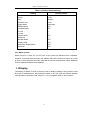
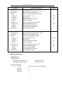
2.4.5 Power-on Defaults
Model TH1912 uses the factory default settings for the power-on settings.
Since the basic measurement procedures in this manual assume the factory defaults,
reset the instrument to the factory settings when following step-by-step procedures. Table
2-1 lists the factory default settings.
12
TH1912 Operation manual
Table 2-1 Factory Default Settings
Setting
Factory Default
DCV
AUTO
Medium
Local
Immediate
OFF
OFF
+1
-1
OFF
+1
OFF
OFF
OFF
OFF
Function
Range
Rate
Remote/Local
Trigger Mode
Relative Mode
Compare Mode
HI Limit
Lo Limit
Percent Mode
Reference
Max/Min Mode
Reading Hold
Secondary Display Mode
Cal Mode
2.4.6 Warm-up time
Model TH1912 is ready for use as soon as the power-up sequence has completed.
However, to achieve rated accuracy and stability, allow the instrument to warm up for half
an hour. If the instrument has been subjected to extreme temperatures, allow additional
time for internal temperatures to stabilize.
2.5 Display
The display of Model TH1912 is primarily used to display readings, along with the units
and type of measurement. Annunciators located on the left, right and bottom indicate
various states of operation. See section 2.2.1 for a complete listing of annunciators.
13
TH1912 Operation manual
Chapter 3 Basic Measurements
3.1 Preparation
One of the first things you would like to do with your Milivoltmeter is to become
acquainted with its front panel. We have provided some exercises in foregoing chapters
about preparations for use and operations of front panel.
The front panel has six rows of keys to select various functions and operations. Most keys
have a shifted function printed in blue above the key. To perform a shifted function, press
(the Shift annunciator will turn on). Then, press the key that has the desired label
above it.
Shift
If you accidentally press
Shift
, just press it again to turn off the Shift annunciator.
3.2 Measuring voltage
TH1912 voltage ranges:3.8 mV, 38mV, 380mV, 3.8V, 38V ,300V(500V peak
value);highest resolution 0.1μV(In 3.8mV range).
Connection method
If TH1912 is under the setting condition, the operational procedure is:
1. Voltage probe BNC is connected to BNC jack(when testing small voltage, probe
ground line should be short as possible to avoid voltage interference).
2. Press Auto to lock auto range function. After booting this function, be attention
AUTO lights. If you need manual range, use
and
to select the test range of
required voltage.
3. Read the reading on the display.
14
TH1912 Operation manual
3.3Select secondary display
At default status, secondary display is displayed by
or
.
Assembled display of secondary parameter,the group is listed as Figure 3-1
3.3.1 Operation
1. Press
+
to open secondary display function.
2. Press
or
to select the assembled group of each secondary
parameter in primary display function, details in shown as figure.
3. Press
+
again to turn off secondary display function, and primary
display can’t be affected.
Figure 3-1
Secondary display
Primary display
V
dBm
dB
W
dBV
Vp-p
dBmV
dBm
dB
W
dBV
Vp-p
dBmV
dBμV
dBμV
V
W
dBV
Vp-p
dBmV
V
dBm
dB
dB
W
dBV
Vp-p
dBμV
dBmV
V
dBm
dBV
Vp-p
dBmV
dBμV
V
dBμV
dBm
Vp-p
W
dBmV
V
dBm
Vp-p
W
dBV
Vp-p
Vp-p
dBμV
dBmV
V
dBm
dB
W
dBV
dBμV
V
dBμV
dBm
dB
W
dBV
Vp-p
dBmV
Percentage (%)
%
Comp
HI,IN,LO,PASS,FAIL
Max/Min
Max
Min
3.4 Math operation function
There are 3 kinds of math operation in TH1912:
· Percentage
· dB
· dBm
15
TH1912 Operation manual
The procedure of selecting and setting math function is as below:
Press corresponding math function key to turn on the function.
Set the parameter of math function, and press
function key, the math function will be cancelled.)
to confirm.(If press the math
3.4.1 Percent
Percent operation is based on the reference value you set:
Percent =
Input Reference
Reference
100%
Where: Input
General display reading on the screen
Reference User inputting parameter
Percent
Calculated result
Application:
The application of Percent math function, please operate based on the following
methods:
Press
+
on secondary display.
to select Percent math function, Percent value is displayed
After opening Percent math function,if you need to change reference value,the
following operation can also be performed except the description above:
1.
2.
3.
Press
+
again to load 3:PERC REF command of A:MATH MEU,
press
to enter parameter setting: +1.0000 。
use
and
to select the required digit,then use
and
to add
or subtract value, and input a required value and unit.
Press
to confirm reference value.
Model TH1912/A will display measurement result of calculation. If the value of “Input”
is larger than that of “Reference”, displayed result will be positive; contrarily, it will be
negative if the value of “Input” is smaller than that of “Reference”.
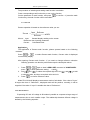
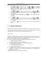
3.4.2 dB calculation
Expressing DC and AC voltage in dB makes it possible to compress a large range of
measurements into a much smaller scope. The relationship between dB and voltage is
defined by the following equation:
16
TH1912 Operation manual
dB = 20 log
Where:
VIN
VREF
VIN is the DC or AC input signal.
VREF is the specified voltage reference level
The instrument will read 0dB when the reference voltage level is applied to the input.
If a relative value is in effect when dB is selected, the value is converted to dB then REL is
applied to dB. If REL is applied after dB has been selected, dB has REL applied to it.
1. Application:
Press dB to select dB math function,dB value is displayed on secondary
display.
After opening dB math function,if you need to change reference value, the following
operation can also be performed:
1. Press Shift +
to load 4:dB REF command in B:MATH MENU,press
key to enter parameter setting:REF:+0.00000.
2. Use
and
to select the digits,then use
and
to increase
or decrease the value, input a demanded value.
3. Press
Auto
to confirm the set reference voltage value.
Note: 1. In calculating dB,say VIN/VREF absolute value.
2. The Max.negtive dB value is -160dB, when,VIN = 1 V,
VREF = 1000V.
2.
TH1912 dual channel dB operation function
TH1912 has the function of channel dB operation,which can perform dB
operation on signal test value of dual channels. The method is:
Press Shift + dB key to open channel dB,now the flashing channel indicates
reference value,use
and
to change reference channel. Press
Auto
to confirm the selected reference channel,the primary display is dB
value. Use
and
to select CH1/CH2 or CH2/CH1.
If selecting a same channel to perform dB,now VREF is the test value of
reference channel when pressing
reference voltage value.
Auto
. Press
and
can display
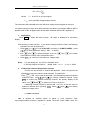
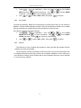
3.4.3 dBm calculation
dBm is defined as decibels above or below a 1mW reference. With
user-programmable reference impedance, Model TH1912/A reads 0dBm when the
17
TH1912 Operation manual
voltage needed to dissipate 1mW through the reference impedance is applied. The
relationship between dBm, reference impedance, and the voltage is defined by the
following equation:
(VIN2
ZREF
1mW
(
dBm = 10 log
Where: VIV is the DC or AC input signal.
Z REF is the specified reference impedance.
If a relative value is in effect when dBm is selected, the value is converted to dBm then
REL is applied to dBm. If REL is applied after dBm has been selected, dBm has REL
applied to it.
Application:
Press dBM to select dBm math function,the secondary display is the dBm value.
1. Press Shift →
to load 5:dBm Zx command in B:MATH MENU,press
to enter parameter setting:REF:0000.
2. Use
and
keys to choose a numerical place and use
keys to increment or decrement the digits. Enter a value from 1Ω to 9999Ω.
3. Press
and
(ENTER) to confirm the reference impedance.
NOTES: The reference impedance and input impedance mentioned in this
chapter are totally different. Input impedance is inherent in the instrument
and could not be changed via foregoing methods.
dBm is valid for both positive and negative DC voltage.
The percent math operations are applied after the dBm or dB math.
18
TH1912 Operation manual
Chapter 4 Measurement Options
This chapter provides description of the front panel features of TH1912. For those
measurement options accessible only by a remote interface, this chapter is organized as
follows:
Measurement Configuration – Describes Ranging, Relative readings, Digits of
Resolution and Measurement rate
Triggering operations – Explains trigger sources
MAX and MIN operations – Records the minimum and the maximum input signals
Limit operations – Defines how to set reading limits
System Operations – Provides details on Beep setup, Baud rate setup, Terminal
character setup and key sound setup up
Measurement configuration
The following paragraphs discuss configuring Milivoltmeter for making measurement.
4.1.1
Range
You can let the millivoltmeter automatically select the range using auto ranging or you
can select a fixed range using manual ranging. Auto ranging is convenient because the
millivoltmeter automatically selects the appropriate range for each measurement.
However, you can use manual ranging for faster measurements since the millivoltmeter
doesn’t have to determine which ranging to use for each measurement. The millivoltmeter
returns back to auto ranging when power has been off or after a remote interface reset.
Maximum readings
The full scale readings for every range on each function are 5% over range
Manual ranging
or
key. The instrument changes one range
To select a range, simply press
per key press. The selected range is displayed for a moment.
If the instrument displays the “OVL.D” message on a particular range, select a higher
range until an on-range reading is displayed. Use the lowest range possible without
causing an overflow to ensure best accuracy and resolution.
19
TH1912 Operation manual
Auto ranging
To enable auto ranging, press
key. The AUTO annunciator turns on when auto
ranging is selected. While auto ranging is selected, the instrument automatically chooses
the best range to measure the applied signal. However, auto ranging should not be used
when optimum speed is required.
Note that up-ranging occurs at 105% of normal range and down-ranging occurs at
5% of normal range.
or
or
key. Pressing
To cancel auto ranging, press
auto ranging leaves the instrument on the present range.
4.1.2
to cancel
Relative
The relative operation could be used to null offsets or subtract a baseline reading
from present and future readings. When relative function is enabled, Model TH1912 uses
the present reading as a relative value. Subsequent readings will be the difference
between the actual input value and the relative value.
You can define a relative value for each function. Once a relative value is set for a
measurement function, the value is the same for all ranges. For example, if 2V is set as a
relative value on the 20V range, the relative is also 2V on the 1000V, 100V, 1V or 100mV
ranges.
Additionally, when you perform a zero correction for DCV, Ω measurements by enabling
REL, the displayed offset becomes the reference value. Subtracting the offset from the
actual input zeroes the display, as follows:
Displayed reading = Actual Input – Reference
Note: as for some range, REL function won’t increase the Max.allowing input signal, for
example: in 3.8V range, for the input signal higher than 3.9V, TH1912 still display
“OVL.D”.
To set a REL value, press Rel when the display shows the value you want as the
relative value. The REL annunciator turns on. Press Rel a second time to disable REL.
20
TH1912 Operation manual
4.1.3
Rate
The RATE operation sets the integration time of the A/D converter, the period of time
the input signal is measured. The integration time affects the usable digits, the amount of
reading noise, as well as the ultimate reading rate of the instrument.
In general, the fastest integration time (FAST set from the front panel or remote interface)
results in increased reading noise and fewer usable digits, while the slowest integration
time provides the best common-mode and normal-mode rejection. In-between settings
are a compromise between speed and noise.
The RATE parameters are explained as follows:
Fast
FAST sets speed to 25 readings per second. Use FAST, if speed is of primary importance,
however it is at the expense of increased reading noise and fewer usable digits.
Medium
Medium sets speed to 10 readings per second. Use Medium when a compromise
between noise performance and speed is acceptable.
Slow
Slow sets speed to 5 readings per second. SLOW provides better noise performance at
the expense of speed.
Note:
The integration time can be set for any measurement function except
frequency, period, continuity (FAST) and diode test (Medium). For
frequency and period, this value is little excess a gate time.
4.2 Trigger operation
The millivoltimeter’s triggering system allows you to generate triggers either manually or
automatically or externally and take multiple readings per trigger. The following
paragraphs discuss front panel triggering, and the reading hold feature.
4.2.1
Trigger procedure
Wait for Trigger
The control source holds up operation until the programmable event occurs and is
detected. See description below for trigger sources:
Immediate
21
TH1912 Operation manual
With this trigger source, event detection is immediately satisfied allowing
operation to continue.
External
Event detection is satisfied for both kinds of triggers as below:
1. A bus trigger (*TRG) command is received.
2. The front panel Trig key is pressed (TH1912/A must be taken out of
remote before it will respond to Trig key).
Take steps below for trigger settings:
1. Press
+
to load“Menu”,then use
or
to find
B:TRIG MEU and press
to enter“Command”,use
or
to find
1:TRIG MODE command , press
to enter parameter(IMM 、 MAN or
BUS)setting.
2. Use
3.
or
to select IMM, MAN or BUS, then press
to confirm.
Measurement Sample
The primary measurement sample action is a measurement. However, the measurement
sample action block could include the following additional actions:
Hold — with hold enabled, the first processed reading becomes the “Seed” reading and
operation loops back within the measurement sample block. After the next reading is
processed, it is checked to see if it is within the selected window (0.01%, 0.1%, 1% and
10%) of the “seed” reading. If the reading is within the window, operation again loops back
within the measurement sample block. This looping continues until the specified number
(2 – 100) consecutive readings are within the winder. If one of the readings is not within
the window, the instrument acquires a new “seed” reading and the hold process
continues.
Reading Hold
When a hold reading is acquired as described in “Measurement Sample”, an audible beep
is sounded (if enabled) and the reading is considered a “true measurement”. The reading
is held on the display until an “out of window” reading occurs to restart the hold process.
The reading hold feature allows you to capture and hold a stable reading on the display.
Take steps below to enable and set reading hold function.
1. Press Shift + Trig to enable reading hold function
2. Press
+
to load“Menu”,then use
or
to find B:TRIG
MEU and press
to enter “command”,use
or
to find 2:HOLD
WIN command,press
to enter parameter selection.
3. Use
or
to select range(0.01% ,0.1% ,1% ,10%),then press
to
confirm the selected range.
22
TH1912 Operation manual
4. Use
to select 3:HOLD CNT , press
setting(Default is 5):
RDGS: 005
to enter parameter
5. Use
and
to choose numeric place, then use
increase and decrease value. Enter a value of count.
6. Press
and
to
to confirm set digits(2~100).
4.3 MAX/MIN
Used to indicate the Max. and Min. value in the process of testing. After opening this
function, the instrument starts to record the Max. and Min. value, as well as keep
refreshing. It can also be used to test wavery range.
Use the following procedure to turn on the turn on the MAX / MIN operation:
to enable the MAX / MIN function
or
key to switch between MAX and MIN.
key again to disable the MAX/MIN function.
1. Press
2. Use
3. Press
4.4 Compare Operations
Limit operations set and control the values that determine the HI / IN / LO status of
subsequent measurements. Limits can be applied to all measurement functions except
continuity. The limit test is performed after percent math operations. Unit prefixes are
applied before the limit test, for example:
Low Limit = -1.0, High Limit = 1.0
A 150mV reading equals 0.15V (IN).
You can configure the millivoltmeter to beep or not when readings are outside of the limit
range.
4.4.1
Enabling compare
Use the following procedure to turn on the limit operation:
Press
4.4.2
Shift
→
to enable or disable LIMIT TEST function.
Setting Compare Limit Values
23
TH1912 Operation manual
Use the following steps to enter high and low limit values:
1.
Press
+
to load“Menu”,then use
or
MEU and press
to enter“Command”,use
or
LIMIT command,press
to enter parameter setting:
HI: +1.0000
2.
Use
and
to change numeric place, then use
increase and decrease the value. Enter a value of count. Press
high limit value.
3.
to select 2:LOW LIMIT,press
Use
setting:
LO: -1.0000
Use
and
to change numeric place, then use
increase and decrease the value. Enter a value of count. Press
low limit value.
5.
Press
status.
→
and
to
to confirm
to enter low limit parameter
4.
Shift
to find A:MATH
to find 1:HIGH
and
to
to confirm
key to exit from the menu and return to the measurement
4.5 System Operations
Model TH1912 has some other operations: Beeper control, key sound control, Baud rate
control and Terminal character setup. The information is not directly related to making
measurements but is an important part of operating the instrument.
4.5.1
Beep
Normally, the millivoltmeter will emit a tone whenever certain conditions are met. For
example: the millivoltmeter will beep when a stable reading is captured in reading hold.
You may want to disable the beeper for certain applications.
z When you disable the beeper, the millivoltmeter will not emit a tone when:
1. A limit is exceeded in a limit test
2. A stable reading is captured in reading hold.
z Disabling the beeper has no effect on the tone generated when:
1. An internal error is generated.
2. The continuity threshold is exceeded.
3. A front panel key is pressed.
z
The beeper state is stored in non-volatile memory and does not change when power
has been off or after a reset. The beeper is enabled when the millivoltmeter is
shipped from the factory.
Use the following steps to change the beeper’s state:
24
TH1912 Operation manual
1.
Press
+
MEU and press
command,press
2.
Use
4.5.2
or
to load“Menu”,then use
to enter“Command”,use
to enter parameter setting.
or
or
to select ON or OFF, then press
to find C:SYS
to find 1: BEEP
to confirm.
Key Sound
To avoid mis-operation, Model TH1912/A has key sound function and you can enable or
disable it. Factory default setting is enabled. The key sound state is stored in non-volatile
memory and does not change when power has been off of after a reset.
Use following steps for key sound setting:
1.
+
to load“Menu” , then use
or
Press
MENU and press
to enter“Command”,use
or
SONG command,press
to enter key sound setting.
2.
Use
4.5.3
or
to select ON or OFF , then press
to find C:SYS
to find 4:KEY
to confirm.
Self-test
The self-test is a tool of testing the instrument, which can help the operator find the
problem as quickly as possible.
TH1912 has the function of booting up self-test, which can prove the instrument can
be operated. Booting up self-test is just a part of self-test operation, but the self-test in
not included in analogy circuit. Please refer to the information about the use of self-test
in TH1912 service manual.
25
TH1912 Operation manual
Chapter 5 Remote Operation
Besides the front panel control, TH1912 supports RS-232 serial interface for remote
control. Standard Commands for Programmable Instruments (SCPI) is fully supported to
communicated with computer via the RS-232 interfaces, with a certain communication
protocols.
You can connect RS-232 interface with a computer. Some considerations will draw your
attention:
You must define the baud rate
You must use the SCPI programming language
5.1 RS-232 Interface Operation
The instrument provides various remote commands. All operations from the front panel
can be performed by a computer via the RS-232 interface.
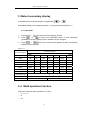
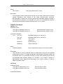
5.1.1 RS-232 Connection
RS232C standard now is widely used as the serial communication standard. RS232
stands for Recommend Standard number 232 and C is the latest revision of the standard.
The serial ports on most instruments use a subset of the RS232C standard. The full
RS232C standard specifies a 25-pin “D” connector of which 22 pins are used. Most of
these pins are not needed for normal serial communications.
Function
Code
25 Pin connector
Pin Number
9 Pin Connector
Pin Number
Request To Send
RTS
4
7
Clear To Send
CTS
5
8
Data Set Ready
DSR
6
6
Data Carrier Detect
DCD
8
1
Data Terminal Ready
DTR
20
4
Transmitted Data
TXD
2
3
Received Data
RXD
3
2
Signal Ground Common
GND
7
5
TH1912 only uses the smallest subset of the RS232C standard, the signal are listed as
below:
26
TH1912 Operation manual
Function
Code
Connector
Pin Number
Transmitted
Data
TXD
3
Received Data
RXD
2
Signal Ground
Common
GND
5
Note: the definition of serial port pin is the same as that of standard 9- core
RS232C connector.
RS-232 connector adopts 9-core DB jack,the pin sequence is shown as the figure
below:
Rear panel connector
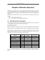
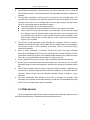
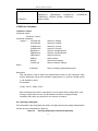
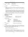
5.1.1
RS-232 operation
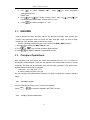
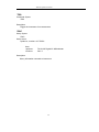
(1). The connection of RS232 and computer is shown as figure 5-1:
DTR(4)
DSR(6)
计算机
RXD(2)
(2) RXD
TXD(3)
(3) TXD
GND(5)
(5) GND
TH1941
RTS(7)
CTS(8)
Figure 5-1 RS-232 connection
There may be some difference between TH1912 RS232 interface and a standard
RS232C interface. You can make the connection cable by yourself according the diagram
or order one from our company.
Note:
Pin 4 and 6, pin 7 and 8 are shorted respectively at the end of controller.
27
TH1912 Operation manual
(2) Sending and receiving data
TH1912 使用含有起始位和停止位的全双工异步通讯传输方式,RS-232 的数据传输格式
为:8 位(bit)数据位,1 位(bit)停止位,没有校验位(bit),结束符为<LF>(换行符,
ASCⅡ代码为 10)。
(3) Selecting Baud Rate
The baud rate is the rate at which Model TH1912 millivoltmeter and the computer
communicate. Choose one of these available rates:
38.4k
19.2k
9600
4800
2400
1200
600
Note:
Factory default baud rate is 9600.
Before you choose a baud rate, make sure the programming terminal that you are
connecting to the TH1912 can support the baud rate you selected. Both the millivoltmeter
and the other device must be configured for the same baud rate.
Perform the following steps to select a baud rate:
1.
Press
+
to load“Menu”,then use
or
to find C:SYS
MEU and press
to enter“Command”,use
or
to find 2:BAUD
RAT command,press
to enter baud rate parameter; you will see:
BAUD:<rate>。
2.
Use
confirm.
3. Press
status.
Shift
or
to select the required baud rate, then press
to
→
key to exit from the menu and return to the measurement
(4) Software Protocol
Since the hardware handshaking lines CTS and RTS are not used by TH1912, the
millivoltmeter uses the character return method to decrease the data losses and errors
during communication. Please refer to the content below before programming
communication software.
1. For command syntax and format, refer to Chapter 6 Command Reference.
28
TH1912 Operation manual
2.
3.
4.
5.
6.
7.
8.
9.
The controller transmits the command using the ASCII code with <LF> or <CR> as
the terminal character. TH1912 executes the command after the terminal character is
received.
The character received by TH1912 will be sent back to the controller again. The
controller will not send the next character until the last returned character is received
correctly from TH1912. If the controller fails to receive the character sent back from
TH1912, the possible reasons are listed as follows:
z The serial interface is not connected correctly.
z Check if the same baud rate is selected for both TH1912 and the controller.
z When TH1912 is busy with executing a bus command, TH1912 will not accept
any character from the serial interface at the same time. So the character sent
by controller will be ignored. In order to make sure the whole command is sent
and received correctly, the character without a return character should be sent
again by the controller.
TH1912 only sends information under following two conditions. The first is when a
character is received normally; TH1912 will send the character back as a handshake.
The second is when a query command is received; TH1912 will send the query
response information.
Once a query command is received, TH1912 will send the query response
information immediately even if the rest commands have not been finished. So if the
command includes two queries, the controller should read the query responses twice.
One query is recommended to be included in a single command.
A query response is sent out in ASCII codes with the preset terminal character.
Several query responses will be sent continuously with 1ms interval. The controller
should be ready to receive the responses; otherwise the response information will be
lost.
The controller should receive the query response terminal character. Otherwise you
will confuse a terminal character with a returned character. At the same time the
controller should receive the last returned character before receiving a query
response.
For some commands that will take a long time to execute, for example reset
command, the controller should keep waiting to avoid the next command being lost
when TH1912 is executing the former command.
.
5.2 Data format
TH1912 outputs the measurement results using the ASCII character string format via
the RS232 serial interface. The data format is described as below:
29
TH1912 Operation manual
SD.DDDDDDESDDD<NL>
S: +/D: number 0 to 9
E: exponent sign (“+”is omitted)
<NL>: New Line, ASCII code is 10
30
TH1912 Operation manual
Chapter 6 SCPI Command Reference
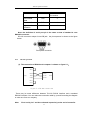
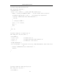
6.1 Command structure
TH1912 commands are divided into two types: common commands and SCPI commands.
The common commands are defined in IEEE std. 488.2-1987, and these commands are
common for all devices. Not all commands are supported by the TH1912. The SCPI
commands are used to control all of the TH1912's functions. The SCPI commands are
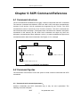
tree structured three levels deep. (The highest level commands are called the subsystem
commands in this manual.) So the lower level commands are legal only when the
subsystem commands have been selected. A colon (:) is used to separate the higher level
commands and the lower level commands. See Figure 6-1 for a sample.
SENSe
RESistance
HOLD
RANGe
SENS:RES:RANG 1k
STATe
SENS:HOLD:STAT ON
AUTO
SENS:RES:RANG:AUTO ON
Figure 6-1 Command Tree Example
6.2 Command Syntax
The information in this section covers the syntax for both common commands and SCPI
commands.
6.1.1 Commands and command parameters:
Common commands and SCPI commands may or may not use a parameter. The
following are some examples:
*RST
No parameter used
31
TH1912 Operation manual
:FORMat <name> Parameter<name> required
:IMMediate
No parameter used
Put at least one space between the command word and the parameter.
z Brackets [ ]: Some command words are enclosed in brackets. These brackets are
used to denote an optional command word that does not need to be included in the
program message. For example:
:RANGe[:UPPer] <n>
These brackets indicate that :UPPer is optional and does not have to be used. Thus,
the above command can be sent in one of the two ways below:
or
:RANGe <n>
:RANGe:UPPer <n>
NOTICE: When using optional command words in your program, do not
include the brackets.
z
Angel brackets <>: Angle brackets are used to denote a parameter type. Do not
include the brackets in the program message. For example:
:HOLD:STATe <b>
The <b> indicates that a Boolean-type parameter is required. Thus, to enable the
HOLD feature, you must send the command with ON or 1 parameter as below:
or
z
:HOLD:STATe ON
:HOLD:STATe 1
Parameter types: The following are some of the more common parameter types:
<b>
Boolean: Used to enable or disable an instrument operation. 0 or OFF
disables the operation and 1 or ON enables the operation. Example:
:CURRent:AC:RANGe:AUTO
<name>
Example:
ON
Enable auto ranging
Name parameter: Select a parameter name from a listed group.
<name> =
MOVing
REPeat
:RESistance:AVERage:TCONtrol
32
MOVing
TH1912 Operation manual
<NRf>
Numeric Representation format: This parameter is a number that can
be expressed as an integer (e.g., 6), a real number (e.g., 25.3) or an
exponent (e.g., 5.6E2). Example:
:MMFactor 5
<n>
Numeric value: A numeric value parameter can consist of a NRf
number or one of the following name parameters: DEFault, MINimum,
MAXimum. When DEFault parameter is used, the instrument is
programmed to the *RST default value. When the MINimum
parameter is used, the instrument is programmed to the lowest
allowable value. When the MAXimum parameter is used, the
instrument is programmed to the largest allowable value. Examples:
:CURRent[:DC]:NPLCycles 1
:CURRent[:DC]:NPLCycles DEFault
:CURRent[:DC]:NPLCycles MINimum
:CURRent[:DC]:NPLCycles MAXimum
6.2.2 Short-form Rules
Use the following rules to determine the short-form version of any SCPI command:
z If the length of the command word is four letters or less, no short form version exists.
Example:
:AUTO =:AUTO
z These rules apply to command words that exceed four letters:
z If the fourth letter of the command word is a vowel, delete it and all the letters after it.
Example:
:immediate =:imm
z Rule exception – The short form version of the following command uses only the first
two letters of the word.
:TCouple = :tc
z If the fourth letter of the command word is a consonant, retain it but drop all the
letters after it. Example:
:format = :form
z If the command contains a question mark (?; query) or a non-optional number
included in the command word, you must include it in the short-form version.
Example:
:delay? = :del?
z Command words or characters that are enclosed in brackets ([ ]) are optional and
need not be included in the program message.
33
TH1912 Operation manual
6.2.3 Basic Rules of Command Structure
z
z
z
z
Letter case (upper and low) is ignored.
For example:
FUNC:VOLT:DC = func:volt:dc = Func:Volt:Dc
Spaces (︺ is used to indicate a space) must not be placed before and/or after the
colon (:).
For example:
(wrong) FUNC︺:︺VOLT:DC
(right) FUNC: VOLT:DC
The command can be completely spelled out or in abbreviated type. (In the following
description, short form will be printed in upper case.)
For example:
FUNCTION: VOLTAGE:DC = FUNC:VOLT:DC
The command header should be followed by a question mark (?) to generate a query
for that command.
For example:
FUNC?
6.2.4Multiple Command Rules
The semicolon (;) can be used as a separator to execute multiple commands on a single
line. The multiple command rules are as follows.
z Commands at the same level and in the same subsystem command group can be
separated by a semicolon (;) on a multiple command line.
For example:
:RESistance:NPLCycle <n>;NPLCycles ?
z To restart commands from the highest level, a semicolon (;) must be used as the
separator, and then a leading colon (:), which shows that the restarted command is a
command at the top of the command tree, must follow.
For example:
:RESistance:NPLCycle <n>; :RESistance:NPLCycles ?
z The common commands can restart only after a semicolon on a multiple command
line.
For example,
:RESistance:NPLCycles<n>;*IDN?
6.2.5 Command Path Rules
z
Each new program message must begin with the root command, unless it is optional
(e.g., FUNCtion). If the root is optional, simply treat a command word on the next
34
TH1912 Operation manual
z
z
z
z
level as the root.
The colon at the beginning of a program message is optional and need not be used.
Example:
:DISPlay:ENABle <b> = DISPlay:ENABle <b>
When the path pointer detects a colon(;), it moves down to the next command level.
When the path pointer detects a colon (:) after a semicolon (;), it resets back to the
root level.
The path pointer can only move down. It cannot be moved up a level. Executing a
command at a higher level requires that you start over at the root command.
35
TH1912 Operation manual
Command Reference
Model TH1912 provides following subsystem commands:
◆ DISPlay ◆ FUNCtion ◆ VOLTage ◆ CURRent ◆ RESIstance
FREQuency
◆ PERiod ◆ HOLD
◆ TRIGer ◆ FETCh
Model TH1912 supports following common commands:
◆ *RST
◆ *TRG
◆ *IDN
◆
6.3.1 DISPlay subsystem
The DISPlay subsystem commands are mainly used to control the display of the
TH1912/A. and are summarized in Table 6-1.
Table 6-1
DISPlay Subsystem Commands Summary
Command
Function Description
:DISPlay
:ENABle <b>
:ENABle?
Enable or disable front panel dispaly
Query state of the display
:ENABle <b>
Command syntax:
:DISPlay:ENABle <b>
Command Parameter:
<b> = 0 or OFF
1 or ON
Query:
:ENABle?
Disable front panel display
Enable front panel display
Query state of the display
Description:This command is used to enable or disable front panel display circuitry. When
disabled, the instrument operates at a higher speed. While disabled, the display is frozen.
All front panel controls except LOCAL are disabled. Normal display operation can be
resumed by using:ENABle command or pressing LOCAL key to enable the display.
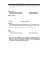
6.3.2 FUNCtion subsystem
The commands in this subsystem are used to configure the measurement function
subsystems and are summarized in Table 6-2.
Table 6-2
FUNCtion Subsystem Commands Summary
Command
Decription
36
TH1912 Operation manual
:FUNCtion
<name>
:FUNCtion?
Select measurement function : ‘VOLTage:AC’, ‘VOLTage:DC’,
‘RESistance’, ‘FRESistance’, ‘CURRent:AC’, ‘CURRent:DC’,
‘FREQuency’, ‘PERiod’, ‘DIODe’, ‘CONTinuity’.
Query function.
:FUNCtion Command
:FUNCtion <name>
Command syntax:
:FUNCtion <name>
Command Parameter:
<name> = ‘VOLTage:AC’
‘VOLTage:DC’
‘CURRent:AC’
‘CURRent:DC’
‘RESistance’
‘FRESistance’
‘FREQuency’
‘PERiod’
‘DIODe’
‘CONTinuity’
Query:
:FUNCtion?
Select AC Voltage
Select DC Voltage
Select AC Current
Select DC Current
Select 2-wire Resistance
Select 4-wire Resistance
Select Frequency
Select Period
Select Diode Testing
Select Continuity Testing
Query currently programmed function
Description:
This command is used to select the measurement function of the instrument. Note
that the parameter names are enclosed in single quotes (’). However, double quotes
(“) can instead be used.
For example:
:FUNC ‘VOLT’= :FUNC “VOLT”
Each measurement function “remembers” its own unique setup configuration, such
as range, speed, filter and rel. This eliminates the need to re-program setup
conditions every time you switch from one function to another.
6.3.3 VOLTage subsystem
The commands in this subsystem are used to configure and control voltage measurement
function and are summarized in Table 6-3.
Table 6-3
VOLTage Subsystem Commands Summary
37
TH1912 Operation manual
Command
Function Description
:VOLTage:DC
:NPLCycles <n>
:NPLCycles?
:RANGe
[:UPPer] <n〉
[:UPPer]?
:AUTO <b>
:AUTO?
:REFerence <n>
:STATe <b>
:STATe?
:ACQuire
:REFerence?
Path to configure DC voltage
Set integration rate (line cycle; 0.5 to 2)
Query line cycle integration rate
Path to configure measurement range
Select range (0 to 1010)
Query range
Enable or disable auto range
Query auto range
Specify reference (-1010 to 1010)
Enable or disable reference
Query state of reference (0,1)
Use input signal as reference.
Query reference value
:VOLTage:AC
:NPLCycles <n>
:NPLCycles?
:RANGe
[:UPPer] <n〉
[:UPPer]?
:AUTO <b>
:AUTO?
:REFerence <n>
:STATe <b>
:STATe?
:ACQuire
:REFerence?
Path to configure AC voltage
Set integration rate (line cycles; 0.5 to 2)
Query line cycle integration rate
Path to set measurement range
Select range (0 to 757.5)
Query range
Enable or disable auto range
Query auto range
specify reference (-757.5 to 757.5)
Enable or disable reference
Query state of reference
Use input signal as reference
Query reference value
Speed Commands
: NPLCycles <n>
Command Systac:
:VOLTage:AC:NPLCycles <n>
:VOLTage:DC:NPLCycles <n>
Command Parameter:
<n> = 0.5 to 2
DEFault
MINimum
MAXimum
Set NPLC for ACV
Set NPLC for DCV
Set power line cycles per integration
1
0.5
2
38
Default
1
1000
ON
0
OFF
1
757.5
ON
0
OFF
TH1912 Operation manual
Query:
:NPLCycles?
Query programmed NPLC value
Description:
The integration period (measurement speed) for the basic measurement functions
(except Frequency and Period) is set using the:NPLCycles command.
NPLC(Number of Power Line Cycles) expresses the integration period by basing it
on the power line frequency. For example, for a PLC of 1, the integration period in
seconds would be1/60 (for 60Hz line power) which is 16.67 msec.
:RANGe Commands
:[UPPer] <n>
Command syntax:
:VOLTage:AC:RANGe[:UPPer] <n>
:VOLTage:DC:RANGe[:UPPer] <n>
Command Parameter:
<n> = 0 to 757.5
0 to 1010
DEFault
MINimum
MAXimum
Query:
:RANGe[:UPPer]?
Set measurement range for ACV
Set measurement range for DCV
Expected reading is AC volts (ACV)
Expected reading is DC volts (DCV)
757.5 (ACV)
1000 (DCV)
0 (All functions)
Same as DEFault
Query measurement range of the current function.
Description:
This command is used to manually select the measurement range for the specified
measurement function. The range is selected by specifying the expected reading as
an absolute value. The instrument will then go to the most sensitive range that will
accommodate that expected reading. For example, if you expect a reading of
approximately 20mV, simply let the parameter (<n>) =0.02 (or 20e-3) in order to
select the 200mV range.
:AUTO <b>
Command syntax:
:VOLTage:AC:RANGe:AUTO <b>
:VOLTage:DC:RANGe:AUTO <b>
Set auto range for ACV
Set auto range for DCV
Command parameter:
39
TH1912 Operation manual
<b> =
1 or ON
0 or OFF
Query:
:AUTO?
Enable auto range
Disable auto range
Query auto range (ON or OFF)
Description:
These command are used to control auto ranging. With auto ranging enabled, the
instrument automatically goes to the most sensitive range to perform the
measurement.
The auto range command (:RANGe:AUTO) is coupled to the command that manually
selects the measurement range (:RANGe <n>). When auto range is enabled, the
parameter value for :RANGe <n> changes to the automatically selected range value.
Thus, when auto range is disabled, the instrument remains at the automatically
selected range. When a valid :RANGe <n> command is sent, auto ranging disables.
:REFerence <n> Commands
:REFerence <n>
Command syntax:
:VOLTage:AC:REFerence <n>
:VOLTage:DC:REFerence <n>
Command parameter:
<n> = -757.5 to 757.5
-1010 to 1010
DEFault
MINimum
MAXimum
Query:
:REFerence?
Specify reference for ACV
Specify reference for DCV
Reference for ACV
Reference for DCV
0 (All measurement functions)
Mininum value for specified function
Maximum value for specified function
Query reference for relative function
Descripton:
These commands are used to establish a reference value for the specified function.
When reference is enabled (:REFerence:STATe), the result will be the algebraic
difference between the input signal and the reference value:
Reading = Input signal – Reference
From the front panel, reference is called relative (REL).
The:REFerence <n> command is coupled to the :ACQuire command. The last
command sent (:REFerence <n> or :ACQuire) eatablishes the reference. When a
reference is set using the:REFerence <n> command, the REFerence? Query
40
TH1912 Operation manual
command returns the programmed value. Conversely, when a reference is set using
the:ACQuiry command, the:REFerence? Query command returns the acquired
reference value.
:STATe <b>
Command syntax:
:VOLTage:AC:REFerence:STATe <b>
:VOLTage:DC:REFerence:STATe <b>
Control reference for ACV
Control reference for DCV
Command parameter:
<b> = 1 or ON
0 or OFF
Enable reference
Disable reference
Query:
:STATe?
Query state of reference.
Description:
These commands are used to enable or disable Reference for the specified function.
When enabled, the displayed reading will include the programmed reference value.
When disabled, the displayed reading will not include the reference value.
:ACQuire
Command syntax:
:VOLTage:AC:REFerence:ACQuire
:VOLTage:DC:REFerence:ACQuire
Acquire reference for ACV
Acquire reference for DCV
Description:
When one of these commands is sent, the measurement input signal is acquired and
established as the reference value. This command is typically used to zero the
display. For example, if the instrument is displaying a 1μV offset, sending this
command and enabling Reference zeroes the display.
This command is functional only if the instrument is on the specified measurement
function. Sending this command while in any other function causes an error. Also, if
the latest reading is overflowed or a reading has not been triggered, an error occurs
when this command is sent.
41
TH1912 Operation manual
6.3.4 HOLD subsystem
The commands in this subsystem are used to configure and control hold measurement
function and are summarized in Table below
Command
:HOLD
:WINDow <NRf>
:WINDow?
:COUNt <NRf>
:COUNt?
:STATe <NRf>
:STATe?
Function Description
Path to control Hold feature:
Set Hold window(%); 0.01 to 10
Query Hold window
Set Hold count; 2 to 100
Query HOLD count
Enable or disable HOLD
Query state of HOLD
Default
1
5
OFF
:HOLD Command
The following commands are used to configure and control the HOLD feature.
:WINDow <NRf>
Command syntax:
:HOLD:WINDow <NRf>
Command Parameter:
<NRf> =
0.01 to 10
Query:
:WINDow?
Set window (percent)
Query Hold window
Description:
This command is used to set the window for HOLD. This window is expressed as a
percent of the “seed” reading for the Hold process.
:COUNt <NRf>
Command syntax:
:HOLD:COUNt <NRf>
42
TH1912 Operation manual
Command Parameter:
<NRf> =
2 to 100
Specify HOLD count
Query:
:COUNt?
Query HOLD count.
Descripton:
This command is used to specify the count for HOLD. COUNt is the number of
readings that are compared to the “seed” reading during the HOLD process.
:STATe <b>
Command syntax:
:HOLD:STATe <b>
Command Parameter:
<b> = 0 or OFF
1 or ON
Query:
:STATe?
Disable HOLD
Enable HOLD
Query state of HOLD
6.3.5 TRIGger subsystem
These commands in this subsystem are used to configure and control trigger
measurement function and are summarized in Table below
Command
:TRIGger
:SOURce <name>
:SOURce?
Function Description
Select control source
Query control source
Default
IMMediate
:TRIGger
TRIGger subsystem commands are used for the instrument settings of trigger mode,
trigger delay and trigger a measurement.
:SOURce <name>
Command Syntax:
TRIGger:SOURce <name>
Command parameter:
<name> = IMMediate
BUS
instrument default setting is internal trigger)
Triggered via RS232 interface)
43
TH1912 Operation manual
MANual(EXTernal)
Query:
:SOURce?
(Press
Trig
in the front panel for Trigger)
Query control source)
Description:
These are used to select the event control source.
6.3.6 FETCH Subsystem
FETCh? Command
Command syntax:
:FETCh?
Description:
This query command is used to obtain the lastest post-processed reading. This
command does not affect the configuration of the instrument.
This command does not trigger a measurement. The command simply requests the
last available reading. This command continues to return the same old reading, until
there is a new reading.
This command will be automatically asserted when :READ? or :MEASure?
command is sent.
6.3.7 Common Commands
Common commands can be used to all equipments. We provide some common
commands as below:
*RST
Command Syntax:
*RST
Description:
Reset the instrument
44
TH1912 Operation manual
*TRG
Command Syntax:
*TRG
Description:
Trigger the instrument for measurement
*IDN?
Query Syntax:
*IDN?
Query return:
<product>,<version><LF^END>
Here:
<product>
<version>
TH1912/A Digital AC Milivoltmeter
Ver1.0
Description:
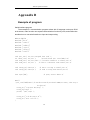
Query information returned to instrument
45
TH1912 Operation manual
Appendix A
Specification
Introduction
Appendix A describes the complete specifications of the Model TH1912 Millivoltemter.
Technical Specifications
·Specifications Assumptions
●
One year calibration cycle.
Operating temperature at 18℃ to 28℃
Accuracy is expressed as: ±(% of reading + digits) after 30 minutes’ warm-up.
Temperature Coefficient: add ± [0.1% × (the applicable accuracy)/℃] for 0℃ to
18℃ and 28℃ to 40℃;
Relative Humidity: Up to 80% for 0℃ to 28℃. Up to 70 for 28℃ to 40℃.
Displayed reading and reading rate
Full scale reading :
●
Slow
Med
Fast
38000
38000
3800
Frequency response error of test voltage:(f=1KHz)
•
•
•
•
•
5Hz~20Hz
±(reading4%+full range0.5%)
>20Hz~2MHz ±(reading 2%+full range0.5%)
>2MHz~3MHz ±(reading 3%+full range0.5%)
>3MHz~5MHz ±(reading 4%+full range0.5%)
Triggering and Memory
46
TH1912 Operation manual
Reading hold sensitivity: 0.01%, 0.1%, 1% or 10% of reading
Programming trigger delay: 0~6000ms (with step of 1ms)
Memory: save 512 reading
Math function
Rel, Max./Min./Average/standard error (stored reading) ,dBm, dB, Limit Test, % and
mX+b.
dBm reference resistance value:automatically set 1Ω ~ 9999Ω(with the stepper of
1Ω),default is 75Ω.
Standard program language
SCPI(Standard Commands for Programmable Instruments)
Remote interface
GPIB(IEEE-488.2) and RS-232C
General specification
Power requirement: 220V±10%
Power frequency: 50/60Hz±5%
Power consumption: ≤20VA
Working temperature: 0℃~40℃,≤90%RH,
Stored environment: -40℃~70℃
Warming up time: at least 30 minuets
Dimention(W×H×D):225mm×100mm×315mm
Weight: about 2.5 Kg
Warrenty period:2 years
47
TH1912 Operation manual
Appwndix B
Example of program
Serial interface program
The example is a communication program written with C language under pure DOS
environment, main function can expand communication function by user, and subfunction
decribes how to use serial interface to input and output string.
#define PORT 0
#include "dos.h"
#include "stdio.h"
#include "stdlib.h"
#include "ctype.h"
#include "string.h"
#include "conio.h"
void port_init(
int check_stat(
void send_port(
char read_port(
int
int
int
int
port,unsigned char code );
port );
/* read serial port state(16bit) */
port,char c );/* send a character to serial port */
port );
/* recive a character form serial port */
void string_wr( char *ps );
void string_rd( char *ps );
/* write a string to serial port */
/* read a string from serial port */
char input[256];
/* quary recieve bufer */
main()
{ port_init( PORT,0xe3 );/* initilize serial port:baud = 9600,no verify,1 bit stop,8
bit data */
string_wr( "trig:sour bus;*trg" );
string_rd( input );
printf( "\n%s",input );
string_wr( "volt:dc:rang 1.0" );
string_wr( "func ‘volt:ac’ );
}
48
TH1912 Operation manual
/* write string to serial port */
void string_wr( char *ps )
{ char c;
int m,n;
while( check_stat(PORT) & 256) read_port(PORT);/* read data until null */
for( ;*ps; )
{ c = 0;
for( m = 100;m;m-- )
{ send_port( PORT,*ps );
for( n = 1000;n;n-- )
{ delay(2); /* wait about 2ms,can use dos.h libray funtion:delay */
if( kbhit() && ( getch() == 27 ) ) /* if escape key keypress */
{ printf( "\nE20:Serial Port Write Canceled!" );
exit(1);
}
if( check_stat(PORT) & 256 )
{ c = read_port( PORT );
break;
}
}
if( n ) break;
}
if( c == *ps ) ps++;
else
{ printf( "\nE10:Serial Port Write Echo Error!" );
exit(1);
}
}
send_port( PORT,'\n' );/* send command end symbol */
delay( 2 );
while( !(check_stat(PORT) & 256) );
read_port( PORT );
}
49
TH1912 Operation manual
/* read string from serial port */
void string_rd( char *ps )
{ unsigned char c,i;
for( i = 0;i < 255;i++ ) /* max read 256 characters */
{ while( ! (check_stat(PORT) & 256) )
/* wait serial recieve ready */
if( kbhit() && (getch() == 27) )
/* if escape key keypress */
{ printf( "\nE21:Serial Port Read Canceled!" );
exit(1);
}
c = read_port( PORT );
if( c == '\n' ) break;
*ps = c;
ps++;
}
*ps = 0;
}
/* send a character to serial port */
void send_port( int port,char c )
{ union REGS r;
r.x.dx = port;
/* serial port */
r.h.ah = 1;
/* int14 function1:send character */
r.h.al = c;
/* character to be sent */
int86( 0x14,&r,&r );
if( r.h.ah & 128 ) /* check ah.7,if set by int86( 0x14,&r,&r ),mean trans error
*/
{ printf( "\nE00:Serial port send error!" );
exit(1);
}
}
/* read a character from serial port */
char read_port( int port )
{ union REGS r;
50
TH1912 Operation manual
r.x.dx = port;
/* serial port */
r.h.ah = 2;
/* int14 function2:read character */
int86( 0x14,&r,&r );
if( r.h.ah & 128 )
/* if ah.7 be set,mean trans error */
{ printf( "\nE01:Serial port read error!" );
exit(1);
}
return r.h.al;
}
/* check the status of serial port */
int check_stat( int port )
{ union REGS r;
r.x.dx = port;
/* serial port */
r.h.ah = 3;
/* int14 function3:read status */
int86( 0x14,&r,&r );
return r.x.ax;
/* ax.7 show serial operation, ax.8 show serial recive ready
*/
}
/* initialize the serial port */
void port_init( int port,unsigned char code )
{ union REGS r;
r.x.dx = port;
/* serial port */
r.h.ah = 0;
/* int14 function0:initial serial port */
r.h.al = code;
/* initialization code */
int86( 0x14,&r,&r );
}
51