1
BSS Audio
V 3.0
DPR-402 User Manual v3.0
JMK
27th October 1997
DPR-402
User Manual
This equipment has been tested and found to comply with the following European and
international Standards for Electromagnetic Compatibility and Electrical Safety:
Radiated Emissions (EU):
RF Immunity (EU):
EN55013
EN50082/1
Mains Disturbance (EU):
Electrical Safety (EU):
Radiated Emissions (USA):
Electrical Safety (USA):
Electrical Safety (CAN):
EN61000/3/2
EN60065
FCC part 15 Class B
UL813/ETL
UL813/ETLc
(1990) Associated Equipment
(1992) RF Immunity, Fast Transients
ESD
(1995)
(1993)
(1996) Commercial Audio Equipment
(1996) Commercial Audio Equipment
IMPORTANT SAFETY INFORMATION
DO NOT REMOVE COVERS. NO USER SERVICEABLE PARTS INSIDE, REFER SERVICING
TO QUALIFIED SERVICE PERSONNEL. THIS EQUIPMENT MUST BE EARTHED.
IT SHOULD NOT BE NECESSARY TO REMOVE ANY PROTECTIVE EARTH OR SIGNAL
CABLE SHIELD CONNECTIONS TO PREVENT GROUND LOOPS. ANY SUCH
DISCONNECTIONS ARE OUTSIDE THE RECOMMENDED PRACTISE OF BSS AUDIO
AND WILL RENDER ANY EMC OR SAFETY CERTIFICATION VOID.
For continued compliance with international EMC legislation ensure that all input and
output cables are wired with the cable screen connected to Pin 1 of the XLR connectors.
The input XLR Pin 1 is connected to the chassis via a low value capacitor, providing high
immunity from ground loops whilst ensuring good EMC performance.
We have written this manual with the aim of helping installers and sound engineers to get
to grips with the DPR-402 and obtain its maximum capability. If you are new to BSS
products, we recommend that you begin at the start of the manual.
We welcome any comments or questions regarding the DPR-402 or other BSS products,
and you may contact us at the address or World Wide Web site given in the warranty
section.
Page 1
BSS Audio
DPR-402 User Manual v3.0
Contents
1 Compressors and Limiters
1.1 The need for Gain Control
1.2 Compressors and Limiters
2 The effect of Compression on sound
2.1 Compression
2.2 Attack, Release and Ratio
4
4
5
5
5
6
3 De-essing and Peak Limiting
7
4 The BSS DPR-402
8
5 Earthing Requirements
9
6 Unpacking
9
7 Mechanical Installation
10
8 Mains Power Connection
10
9 Input and Output Connections - Rear Panel Facilities
10
9.1 Inputs
9.2 Outputs
9.3 Stereo Link
9.4 Barrier Strip
9.5 Peak Limiter Switch
10 Compression Controls
10.1 Threshold
10.2 Ratio
10.3 Attack Time
10.4 Release time
10.5 AUTO TIME
10.6 GAIN control
10.7 BYPASS switch
10.8 MODE switch
11 Compression meters
11.1 Below Threshold and Gain Reduction Meter
11.2 Output Level Meter and Meter Input Switch
11.3 MON S.C. switch
12 De-essing and Peak Limiting
12.1 De-essing
12.2 Broadband De-essing and controls
12.3 HF Only De-essing and Controls
12.4 Peak Limiting
10
11
11
11
11
12
12
12
13
13
13
14
14
14
15
15
16
16
16
16
17
18
18
Page 2
BSS Audio
DPR-402 User Manual v3.0
13 Rear Barrier Strip
19
14 Operation and Applications
20
14.1 Compression
14.2 De-essing
14.3 De-essing Wide with Simultaneous Compression
14.4 De-ess Wide with Full Dynamic Control
14.5 De-ess HF with Full Dynamic Control
14.6 Peak Limiting
15 Applications using the Barrier Strip
15.1 Patching of External Equipment
15.2 Repatching of the Barrier Strip for other uses and Special Effects
15.3 Stereo Linking
20
20
21
22
23
24
24
24
25
27
16 Warranty Information
29
17 Specifications
30
17.1 General
17.2 Compressor
17.3 De-esser
17.4 Peak limiter
17.5 Notes
17.6 Facilities
30
30
31
31
31
31
Page 3
BSS Audio
DPR-402 User Manual v3.0
1 Compressors and Limiters
1.1 The need for Gain Control
The human ear excels in its ability to detect an extremely wide range of sound
levels. These can range from the quietest whisper to the roar of a jet aircraft. When
we attempt to reproduce this large range (dynamic range) of sounds with
amplifiers, tape recorders or radio transmitters, we run into one of the fundamental
limitations of electronic or acoustic equipment. In some cases, such as amplifiers,
the dynamic range available is quite good. However, equipment such as tape
recorders and radio transmitters have a restricted usable dynamic range.
What limits the available dynamic range of this equipment is its inherent noise
floor at the bottom end, and the maximum input signal resulting in an acceptable
amount of distortion at the upper end. The usable dynamic range sits in between
these two limits, and it is common practice to operate a piece of equipment at a
level that is somewhat below the upper distortion point, leaving a margin of safety
for the unexpected transient loudness peaks present in program material. The safety
margin is known as headroom, and is generally in the range of 10 to 20dB.
Lowering the standard operating level to increase headroom helps distortion, but
moves the average program level nearer to the noise floor, thereby compromising
the signal to noise performance.
It therefore becomes apparent that to get the most out of an audio system, the
standard operating level must be kept as high as possible without risking distortion.
One solution to this problem is for the operator of the equipment to be
continuously monitoring the program, and manually adjusting the gain to suit the
moment. When the program is quiet, the gain can be increased, and when the
program is loud the gain can be reduced. However, in most types of program there
are instantaneous short duration level peaks or transients, which would be difficult
to anticipate and impossible to respond to in the required time. Even a sound
engineer with the quickest reflexes could not bring the gain knob or fader down
quickly enough.
The need therefore arises for a fast acting automatic gain controlling device which
will track the program material constantly, and which will always adjust the gain to
maximise the signal to noise performance without incurring distortion. This device
is called a compressor or limiter, and is one part of the DPR-402.
Page 4
BSS Audio
DPR-402 User Manual v3.0
1.2 Compressors and Limiters
Compressors and limiters have closely related effects, and in general a limiter will
reduce gain very strongly once a certain level has been reached, whereas a
compressor will act gently, but over a much wider range of volume levels.
A limiter will continuously monitor program levels, but only commence to reduce
gain once the level has exceeded a preset amount. This point is called the
threshold level. Any program level in excess of the threshold will immediately be
reduced to this threshold level.
A compressor will also continuously monitor the program and has a threshold
level. However, program signals in excess of this threshold will be progressively
reduced by an amount (ratio) depending on the degree to which it initially exceeds
the threshold. Generally, threshold levels for compressors are set below the normal
operating level to allow them to reduce the dynamic range of the signal gradually,
so that they are acceptable to following equipment. For limiters, the threshold
point will be set above the operating level in order to provide a maximum level for
signals to following equipment.
2 The effect of Compression on sound
2.1 Compression
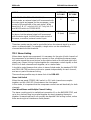
Consider an input signal which is applied to two units, one having its threshold
point set 10dB higher than the other (See figures 2.1 a/b). Since the compressor
only affects signals that exceed the threshold level, that in figure 2.1a will be more
affected than that in figure 2.1b.
Page 5
BSS Audio
DPR-402 User Manual v3.0
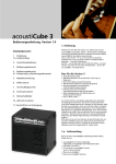
Assuming that all other controls on both channels are set identically with gains
equalised, the processing effect on these signals is shown below.
It is immediately apparent that there is a large difference between these two signals
in relation to their dynamic range, and the signal processed in figure 2.2a is said to
have been compressed, whereas the signal in figure 2.2b is said to have been
limited. Furthermore, it is interesting to note that by comparing the input and
output waveforms for the compressed mode, the quietest portions of the input
signal have been effectively raised in level, whereas the loudest portions have been
effectively decreased in level. The net effect, therefore, is for both ends of the
dynamic spectrum to be pushed (or squeezed) towards each other. This squeezing
effect of compression is important to remember, and provides a major difference
between compression and limiting.
Compression and limiting differ further in one other important aspect, that of the
dynamic time settings for attack and release. For compressors a slow attack and
release time is generally used in order to keep the overall output signal within a
specified dynamic range, whereas for limiting purposes where transient peaks are
to be kept clear of the headroom limits, a faster attack and release time is required.
The range provided by the DPR-402 on its time controls is sufficient to allow its
use either as a compressor or limiter, and the AUTO facility is scaled primarily for
compression use.
2.2 Attack, Release and Ratio
Attack is the amount of time that elapses before the compressor begins to attenuate
the output level after the threshold point has been exceeded. For sounds such as a
snare drum or hand clap, fast attack is desirable so that the compressor responds in
time to control the peaks.
Release is the amount of time taken for the compressor to return to normal gain
after the input signal has fallen BELOW the threshold point.
Ratio determines the ratio of change on output level to changes in input level for
all signals that exceed the threshold. Returning to section 1.1; The need for Gain
Control where the idea of manual controlling the level of the program was
Page 6
BSS Audio
DPR-402 User Manual v3.0
discussed, the operator would reach over and turn down the volume if signal levels
were approaching distortion. At this point he now has an option: Either reduce the
level so that there is nothing exceeding his desired maximum level, or reduce the
level by a small amount so that his output is slightly greater than that of his
preferred maximum but not as loud as it would have been if no action had been
taken. This action is known as the ratio. A ratio of 1:1 indicates that the output will
linearly track the input level of the threshold. i.e. For every 1dB of input over the
threshold point, there will be 1dB of output. A ratio of 2:1 indicates that for every
2dB of input level above the threshold, there will be a corresponding increase of
1dB in the output level. A ratio of 10:1 indicates that for every increase of 10dB of
input level, there will be a corresponding increase of 1dB in the output level, and
so on. A ratio of infinity:1 indicates that no matter how loud the input signal goes
above the threshold, the output will remain constant at the threshold point. It is
worth noting that a hard or infinite ratio limit has applications in some specialised
situations, but in general it is neither appropriate nor necessary, and is likely to
cause noticeable side effects in the sound.
3 De-essing and Peak Limiting
A common problem encountered when amplifying the human voice is the large
amount of High Frequency energy, heard as the sibilant 'sss' sound. These high
frequency or sibilant sounds can reach levels considerably greater than the normal
voice level, and will result in signal break-up or distortion. It is possible to control
these sounds independently of the normal program by making the normal
compressor sensitive only to these high frequencies. Selective high frequency
compression is generally called de-essing, as it removes the 'sss' content from the
program.
Referring to section 2.2; Attack, Release and Ratio, attack time was defined as the
time taken for the compressor to respond to program levels which have exceeded
its threshold level. It is also found that for relatively low frequencies a longer attack
time is required than for high frequencies, to avoid any unpleasant dynamic
distortions. When compressing a program mix that includes a wide range of
frequencies, some compromise must be made to the setting of the attack time, and
this will inevitably result in a setting that suits the lowest frequency components
present. For general dynamic range controlling using a compression mode, this is
of no serious consequence. However, in a limiting mode, where the peaks of the
signal are being restricted to a maximum operating level to avoid distortions in
following equipment, it is essential to have the attack times as fast as possible for
all frequency components. Operating the compressor in a limiting mode, with a
high ratio, high threshold and dynamic settings to suit the low frequency
components, will result in very fast high frequency signal transients passing
through without causing gain reduction. These transients can then cause distortions
in following equipment, such as tape recorders and radio transmitters.
Page 7
BSS Audio
DPR-402 User Manual v3.0
It should be remembered that the DPR-402 is a peak limiter, designed to be used in
conjunction with the main compressor section. If it is used exclusively on its own,
then dynamic distortions will generally result on program signals having anything
other than high frequency content.
4 The BSS DPR-402
The BSS DPR-402 compressor, de-esser and peak limiter has been designed in
response to the demand for a versatile, compact stereo unit which provides the
three most commonly used dynamic functions in a single 1 unit rack space. The
internal architecture, including two independent insert accessible side chains per
channel, allows unprecedented flexibility and scope for the creative operator. In its
normal mode, however, this complexity remains totally invisible for the user who
required a conventional system with operational simplicity.
The dedicated de-esser control and associated variable filter allow wide band
sibilance control simultaneously with compression and peak limiting. For highly
critical de-essing application, the compressor section can be switched to operate at
high frequencies only, i.e.: as a dynamically controlled tunable HF filter.
The compressor section allows you full control over all the normal parameters, and
offers 'auto' time constants for general purpose use. The control and subtract side
chain insertion points allow numerous applications for the patching of the units
own, or external, filters to provide dynamic tonal modification. The calibrated peak
limiter allows absolute control without having to compromise the dynamics setting
of the compressor, potentially resulting in less dynamic distortion for an equivalent
amount of compression.
The DPR-402s user friendliness is well demonstrated by the sophisticated yet
uncluttered LED metering and monitoring facilities. The full compressor operating
range is displayed on a two part meter, indicating both signals below threshold and
actual gain reduction. The arrangement of these two meters, together with the full
scale 'bright-up' feature, ensures that operation will always be within the permitted
VCA window, making it virtually impossible to exceed the systems parameters
unintentionally.
The output is continuously monitored on the output level meter, which also
incorporates the full scale 'bright-up' facility. The bypass switch, in conjunction
with the meter input switch, provides a powerful aid for initially setting up the unit.
The straight signal and the processed signal may be monitored on the output level
meter without affecting the output from the unit, thus enabling system gains to be
equalised while in the bypass mode.
Like all BSS Audio equipment, the DPR-402 has been designed to withstand harsh
treatment on the road, yet has a specification to satisfy the most stringent studio
and broadcast work.
Page 8
BSS Audio
DPR-402 User Manual v3.0
5 Earthing Requirements
WARNING! THIS APPLIANCE MUST BE EARTHED.
IMPORTANT: The wires in the mains lead are colour coded in accordance with
the following code.
Green and Yellow......Earth
Blue......Neutral
Brown......Live
As the colours of the wires in the mains lead may not correspond with the
markings identifying the terminals in your plug, proceed as follows.
• The wire which is coloured Green and Yellow or Green must be connected to
the terminal which is marked with the letter ‘E’ or by the Earth signal or which is
coloured Green and Yellow or Green.
• The wire which is coloured Blue must be connected to the terminal labelled ‘N’
or coloured Black or Blue.
• The wire which is coloured Brown must be connected to the terminal labelled
‘L’ or coloured Red or Brown.
Those units supplied to the North American market will have an integral moulded
3 pin connector which is provided to satisfy required local standards.
The mains voltage selector switch provides a simple external adjustment to allow
operation on all international AC power standards. The allowable ranges for the
supply voltage are:
90VAC up to 132VAC on the 115V position and
190VAC up to 264VAC on the 230V position.
Outside these ranges the unit will not work satisfactorily, if at all. Voltages in
excess of the maximum will probably cause damage. Voltages below the minimum
will cause the power supplies to drop out of regulation, degrading the performance
of the system.
6 Unpacking
As part of BSS' system of quality control, this product is carefully inspected before
packing to ensure flawless appearance.
After unpacking the unit, please inspect for any physical damage and retain the
shipping carton and ALL relevant packing materials for use should the unit need
returning.
In the event that damage has occurred, please notify your dealer immediately, so
that a written claim to cover the damages can be initiated.
Page 9
BSS Audio
DPR-402 User Manual v3.0
7 Mechanical Installation
A vertical rack space of 1U (1¾" / 10½mm) deep is required. Ventilation gaps are
unnecessary.
If the DPR-402 is likely to undergo extreme vibration through extensive road
trucking and touring, it is advisable to support the unit at the rear and/or sides to
lessen the stress on the front mounting flange. The necessary support can generally
be bought ready-built, as a rack tray. As with any low-level signal processing
electronics, it is best to avoid mounting the unit next to a strong source of magnetic
radiation, (for example, a high power amplifier), to help keep residual noise levels
in the system to a minimum.
8 Mains Power Connection
Voltage: The DPR-402 operates on either 120 or 240 volt supplies. Use the voltage
selector switch to choose the required voltage setting.
Frequency: Both 60Hz and 50Hz are acceptable.
Grounding: The DPR-402 must always be connected to a 3-wire grounded
('earthed') AC outlet. The rack framework is assumed to be connected to the same
grounding circuit. The unit must NOT be operated unless the power cables ground
('earth') wire is properly terminated - it is important for personal safety, as well as
for proper control over the system grounding.
AC Power Fusing: The incoming line power passes through an anti-surge ('T') fuse,
accessible from the rear panel. If the fuse blows without good reason, refer to
section XX. Always replace with an identical 20mm x 5mm 'T' fuse, rated at either
250mA or 200mA for 240V or 120V settings respectively, for continued protection
from equipment damage and fire.
Power ON: This is indicated the green 'ON' LED located under the CH 'IN'
switches. If this LED is not lit when power is connected and the 'POWER' switch is
depressed.
9 Input and Output Connections - Rear Panel Facilities
9.1 Inputs
The input is a 10K ohm balanced type on a standard 3 pin female XLR which will
accept levels up to +20dBv. The '+' or in-phase connection is to pin 3 and the '-'
or out-of-phase connection is to pin 2. There is no connection to pin 1, and input
cable shielding should be derived from the equipment which is providing the input
signal. When feeding the DPR-402 from unbalanced sources, connect the signal
'hot' to pin 3, and the signal ground to pin 2.
Page 10
BSS Audio
DPR-402 User Manual v3.0
9.2 Outputs
The output connection is a standard 3 pin male XLR. Output impedance is less
than 1 ohm, unbalanced, and full headroom is available into any load 600 ohms
or greater. The signal 'hot' is connected to pin 3, and the ground to pin 2 and pin
1.
For rack mounted unbalanced audio systems, the case (power) ground can be
isolated from the signal by removing an internal wire link associated with channel
one output.
9.3 Stereo Link
This facility enables the two channels of the DPR-402 to be used in a stereo
system, with the result that there is no image shifting under comparison on either
channel. This switch actually couples the detector outputs from both channels
together, so that either one responds to the largest signal present. When in stereo
mode, the front panel 'LINK' LED will illuminate, and care should be taken to
ensure that both channels have their controls set equally. For other methods of
multiple channel coupling, refer to section 14; Operation and Applications.
9.4 Barrier Strip
This interface facility provides various input and output signals to the unit,
allowing other dynamic controlling features to be realised. This strip also includes
the two insertion points for external equipment connections, and in the absence of
these, the two indicated shorting links must be made to allow normal operation of
the unit. Please refer to section 14; Operation and Applications for examples of
possible uses.
9.5 Peak Limiter Switch
This fast/slow selector changes the dynamic response of the peak limiter section to
best suit the particular program material. Please refer to section 12.4; Peak
Limiting for applications and usage.
Page 11
BSS Audio
DPR-402 User Manual v3.0
10 Compression Controls
10.1 Threshold
In the DPR-402, the gain reduction is achieved using a Voltage Controlled
Attenuator with a range or operational 'window' of 30dB. This means that it is
capable of reducing the input signal by up to 30dB or 30 times (the GAIN
REDUCTION METER displays this window showing how much of it is being used).
The voltage level corresponding to the lower boundary of this window is called the
threshold, and input signals below this level cannot cause gain reduction. When
the input level enters the window by exceeding the threshold, gain reduction can
occur (the amount of gain reduction or 'compression' produced being directly
proportional to the amount by which input signal level exceeds the threshold). The
upper boundary of the VCA window is set by the circuitry at a level 30dB above
the threshold. The THRESHOLD control adjusts the threshold relative to the input
signal in order to set the compressor to the required amount of gain reduction. For
example, if the average input is +12dBv and the THRESHOLD control is set to 10dBv, then the top 22dB [12 - (-10) = 22dB] of the signal can be compressed. The
THRESHOLD control is adjustable from -30dBv to over +20dBv.
It should be noted that when the THRESHOLD control is set fully clockwise to the
position marked OUT, this corresponds to a threshold level above +20dBv, so that
no matter how high the input level stage will clip before the threshold is reached,
the signal will reach the output uncompressed.
How the compressor performs on the signal once inside the window is controlled
by the RATIO, ATTACK, and RELEASE controls.
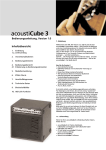
10.2 Ratio
The effect of the ratio control can be shown on a graph which plots input level,
and clearly shows that below threshold the DPR-402 acts purely as a linear
amplifier.
In applications where gentle compression is required, it is advantageous to change
from the linear to compression region in a very gradual manner, rather than the
more conventional abrupt manner, as shown in the diagram. The DPR-402 has
been configured so that for low settings of the ratio control and low levels of
compression, the transfer is soft, and for increasing ratio settings and high levels of
compression the transfer becomes harder. This 'progressive knee' gives inaudible
compression for low levels of ratio and gain reduction, whilst allowing harder
compression for extreme control when required.
Page 12
BSS Audio
DPR-402 User Manual v3.0
10.3 Attack Time
The response of the DPR-402 compressor to signals above the threshold point is
further defined by the ATTACK TIME control.
The DPR-402 ATTACK TIME control has 11 calibrated positions from 50
microseconds to 100 milliseconds, and determines how quickly the compressor
responds to signals once the threshold is exceeded.
As explained earlier, for fast transients, a fast attack time is desirable. For other
types of program material a slower time will be more useful. It is always preferable
to start with a slower time, and progressively speed up the response as necessary,
since too fast a time may cause distortion of the sound.
10.4 Release time
Another parameter which affects the compressor performance is the RELEASE TIME
control.
The release time control has 10 calibrated positions from 5 milliseconds to 5
seconds, and determines how quickly the compressor returns to normal gain
following a transient in excess of the threshold. The setting of the release time is
very much dependant on program type, and the setting of a wrong speed will result
in either of two conditions:
If set too fast; the overall volume level will jump up and down, exactly following
the peaks above threshold, and this will produce an objectional and unsettling
effect.
If set too slow; quiet parts of the program immediately following loud transients
will be subjected to 'breathing' or 'pumping' effects caused by the VCA releasing
its attenuation (or effectively the system gain) during the quiet program period,
when it is not required.
10.5 AUTO TIME
This feature of the DPR-402 is provided to overcome some of the settling problems
associated with the attack and release time control features. It is accessed by
switching the released time control to the 'AUTO' position, whereupon the circuit
automatically adjusts itself to provide the required attack and release time settings,
depending on the program type.
The circuitry combines a program related attack time setting and a two part
program related release time setting. The two part program dependant release
provides:
A fast release to restore below threshold gain as soon as the transient has passed.
A much longer following release to avoid rapid gain change effects.
Page 13
BSS Audio
DPR-402 User Manual v3.0
Note that once AUTO time has been selected, the attack control becomes
inoperative.
10.6 GAIN control
Because compression is a gain reducing process, the output signal level can often
be lost. The GAIN control is provided to restore this output to normal operating
point, and provides a calibrated range of ±20dB.
The facility of gain loss provided by this control can be used, when required, to
restore the compression to a point lower than the input signal (For example, when
connecting this output to a high sensitivity input on a following piece of
equipment).
10.7 BYPASS switch
The BYPASS switch enables you to bypass quickly all functions of the DPR-402 by
connecting the output directly to the input. When the switch is pressed, and the
light is on, all DPR-402 functions are present on the output signal. When the
switch is out, all facilities are bypassed.
It should be noted that in the bypass mode, the input is still connected to all of the
DPR-402 circuitry, so that all of the required facilities can be selected and set up.
This, in conjunction with the OUTPUT METER and INPUT SWITCH, provides a
powerful tool for comparing processed signals prior to operating the bypass switch
and going 'on-air'.
A further feature of this illuminated switch is to allow coding of each particular
channel with a specific number or letter. By removing the lens-cap with a small
screwdriver or your fingernail, an appropriate symbol can be fitted. This will have
particular advantages in situations where more than one DPR-402 is fitted into a
control rack.
10.8 MODE switch
This control switch reconfigures the compressor to insert the built-in filters into its
side chains, so that gain reduction only occurs when certain frequencies are
present in the input signal.
For normal compression, this switch will always be in the 'compress' position.
Please refer to sections 12.2; Broadband De-essing and controls and 12.3; HF
Only De-essing and Controls for a full explanation of this, and the applications of
de-essing.
Page 14
BSS Audio
DPR-402 User Manual v3.0
11 Compression meters
11.1 Below Threshold and Gain Reduction Meter
Referring back to section 10.1; Threshold, where we discussed the VCA window of
operation, the five LEDs of the BELOW THRESHOLD meter will give you an
indication of the input signal in relation to this window.
You will notice that the LED marked 'TH' is half-on all the time. This point
represents the threshold point as set by the THRESHOLD control, and any signal
level that exceeds this LED will start the compressor operating. Rotating the
threshold control anticlockwise effectively lowers the window of the VCA,
allowing it to sit at the right point on the input signal. Observation of this meter
during program will give an instant picture of how much of the input signal is
being processed, or how near the peaks are to being processed. This will provide
valuable information at all times during use, especially for live concert work,
where signal levels tend to increase during the course of the show.
Once the input signal has exceeded the threshold point on scale, the compressor
starts to operate, and gain reduction will occur. The amount of gain reduction
being used is displayed on the GAIN REDUCTION meter.
Gain reduction is a useful way of expressing compressor action. We have seen that
the output level of a compressor is less than the input level by some amount that
depends on the threshold, ratio, attack and release time settings. If, for example, a
particular signal transient exceeds the threshold point by 10dB and the ratio knob
is set to 2:1, then we would expect the output to have only increased by 5dB
(providing the time controls are set accordingly). Assuming the gain control is at
0dB, the difference between the input and output levels of 5dB then represent the
amount of gain reduction which has occurred and will be displayed on the gain
reduction meter as 5dB.
The range of the gain reduction meter is set to display the 27dB operating window.
In practice, over 30dB of range is available before noticeable distortion occurs.
Another piece of information also displayed by these meters is the amount of gain
reduction still available from the VCAs window of operation. If you consider that
the input signal is of such a level that 15dB of gain reduction is occurring (i.e.: the
15dB LED on the gain reduction meter is on), then the length of GAIN
REDUCTION meter display remaining unlit is an accurate visual indication of how
much headroom still exists within the circuitry. Observing this information will
ensure that the output signal is unlikely to incur distortion as a consequence of
overloading the VCA.
A further operational feature of this meter is its ability to intensify brightness when
the VCA window is in danger of being exceeded and distortion is likely to occur.
Input signals causing an excess of 30dB of gain reduction will initiate the 'brightup' and the display will appear to flash to alert attention. This feature is especially
Page 15
BSS Audio
DPR-402 User Manual v3.0
useful when a rack of equipment contains a number of DPR-402 units; the ability
to immediately pick out the particular channel that is in danger of distortion will be
much appreciated.
11.2 Output Level Meter and Meter Input Switch
This meter monitors the signal level at the output of the DPR-402, and gives an
absolute reading of its level.
This meter also incorporates the 'bright-up' feature, which will occur when the
output signal level reaches +20dBv.
The METER INPUT switch is used in conjunction with the OUTPUT LEVEL meter
to allow the input signal to be displayed. The switch has a momentary action to
ensure that the meter is not inadvertently left showing input level.
This facility becomes extremely useful when used in conjunction with the BYPASS
switch. During initial setting up of routines and prior to going 'on-air', the signal
output level will be different from the input. Utilising this meter input switch will
enable the input and output levels to be compared on the same display, and
adjustments can then be made accordingly with the GAIN control to ensure that
the input and output levels are similar (the GAIN control will only affect the output
signal level). Once satisfied of this condition, operation of the BYPASS switch will
ensure an unnoticeable 'drop-in'.
11.3 MON S.C. switch
This switch will change the output connector of the DPR-402 from the normal
compressor output, and connect it to the return of the control side chain insertion
point. This will allow monitoring of any external equipment which is connected to
the unit to assist in its setting up. For applications and a description of side chain
insertions please refer to sections 13; Rear Barrier Strip and 14; Operation and
Applications.
12 De-essing and Peak Limiting
12.1 De-essing
In section 3; De-essing and Peak Limiting, the problems with high frequency
energy, also known as sibilance, were discussed. The DPR-402 provides for this
facility in either of two distinct ways: Broadband de-essing and HF only de-essing.
Under program conditions, once the detector detects excessive amounts of
frequency, it will start to gain reduce the program level as in normal compression.
Because compression then occurs over the whole frequency range of the program,
it is called Broadband de-essing. To make the compressor sensitive only to high
frequencies, a high pass filter is inserted into the CONTROL side chain insertion
Page 16
BSS Audio
DPR-402 User Manual v3.0
point, with the result that frequencies below the filter cut-off point are excluded.
Once excessive amounts of frequency are detected compression will commence,
but only on those high frequencies program components that initially caused the
compressor to act.
The type of de-essing to be used in a particular situation will depend largely on the
program type and whether the input to the compressor is a mix of sibilant sounds
and other program material, or exclusively the sibilant sound. HF only de-essing
will generally be used when processing a mix of program, whereas broadband deessing will be acceptable when processing only the sibilant sound.
It should be realised that this technique is very different from simple equalisation,
since equalising a sibilant vocal by cutting high frequencies would result in loss of
high frequency content at all times. De-essing has no effect whatsoever on the
signal, except at the moment of sibilance, and then the effect is only of overall
level change. There is no change in the general frequency response, yet sibilance is
controlled.
12.2 Broadband De-essing and controls
Broadband de-essing can be achieved either simultaneously with normal
compression on the same channel of the DPR-402, utilising DE-ESS and FREQ
controls, or exclusively on the one channel by setting the MODE switch to DE-ESS
WIDE, and utilising the compressor section controls.
In utilising the controls no other compressor controls will be required. If no
compression is being used, the ratio or threshold controls should be set to OUT.
The frequency control should be set to coincide with the lowest frequency of the
sibilance, and the de-ess control be used to give the required amount of gain
reduction. The maximum amount of reduction available in this mode is 20dB. The
dynamic settings for this compression are set automatically by the unit, and are
optimised for general vocal work.
The green and orange LEDs above the de-ess control provide a simple indication of
the degree of de-essing, with the green LED indicating the start of the operation
and the orange LED indicating approximately 15dB of gain reduction.
Having only a frequency and level control for this broadband de-essing function
provides a very simple and effective way of treating general sibilant vocal signals,
when processed on their own.
Should the need for more comprehensive control of the de-essing function arise,
then the main compressor section can be configured to operate as a dedicated deesser by operating the mode switch. The amount of gain reduction can then be
extended down to 30dB if required, and this gives full control over the dynamic
settings, as in normal compression.
Page 17
BSS Audio
DPR-402 User Manual v3.0
12.3 HF Only De-essing and Controls
To achieve this mode of operation, the main compressor must be utilised as an
exclusive de-esser by operation of the MODE switch to DE-ESS HF.
Gain reduction at high frequencies only is achieved by inserting an internal high
pass filter into the subtract side chain so that only these high frequencies are
available to the subtractor. The front panel FREQ control adjusts both this filter and
the control side chain filter simultaneously, to provide a de-essing range from
700Hz to 20kHz. HF only de-essing is achieved by operating the compressor
controls as for normal compression (refer to section 10; Compression Controls),
and utilising the FREQ control to allow only the sibilant frequencies to cause gain
reduction. If general compression is required simultaneously, then channel 2 of the
unit can be used by connecting the two channels in series. It should be
remembered that in this mode, the DE-ESS and PEAK LIM controls must be set to
OUT, as they cannot be used simultaneously with the compressor switched to
dedicated de-ess mode.
To aid the correct setting of the FREQ control in relation to the audible sibilance,
the source program can be listened to through the internal de-ess filter by
depressing the MON S.C. switch. This replaces the normal signal at the output
connector with the output of the de-ess filter.
12.4 Peak Limiting
Referring back to section 3; De-essing and Peak Limiting, the problems with high
frequency transients causing distortion further down the equipment line were
discussed. The peak limiter of the DPR-402 provides an extra stage of gain
reduction, with dynamics specifically set for these fast transients. It is used in
conjunction with the main compressor section and provides an output limiting
function to control the fast transients which would generally be missed by the
slower dynamic settings of the compressor. The attack and release times are set
internally to suit the limiting application, with a choice of FAST or SLOW response
selected by a switch on the rear panel (refer to section 9; Input and Output
Connections - Rear Panel Facilities). It is preferable to use the FAST response
setting, providing this does not cause audible distortion, otherwise the SLOW
response should be used.
The peak limiter threshold is unaffected by the GAIN control, and is set by the
PEAK LIM control, which is scaled directly in dBv. The ratio is set internally to
20:1. A green LED is provided to indicate when limiting begins, and a red LED
indicates when heavy limiting occurs (above 10dB). This red LED indicates that
more than optimum peak limiting is being used, and the output gain control should
therefore be backed off, so that it only flashes on occasional peaks.
Page 18
BSS Audio
DPR-402 User Manual v3.0
13 Rear Barrier Strip
The DPR-402s rear barrier strip provides an interface with the main compressor
section, allowing for various configurations which utilise the internal facilities as
well as external equipment. For correct operation of the unit, make sure that both
the SUBTRACT and CONTROL side chain points are closed, either by links or by
externally connected equipment. Connections to the subtract side chain will be
phase conscious, whereas those to the control will not be. Any externally
connected equipment should operate at unity gain, and be capable of handling
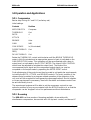
signal levels up to +20dBv.
Rear Barrier Strip Designations
Pin
Function
A
Ground
B
Insert Return: Control Side Chain
C
Insert Send: Reversed Phase
D
Insert Send: Normal Phase
E
Insert Send: L.F. Re-emphasised
F
Insert Send: H.F. Re-emphasised
G
Insert Return: Subtract Side Chain
H
Insert Return: Subtract Side Chain Gain Link
(Expand or over infinity mode)
J
Ground
K
Insert Send: Subtract LP Filter
L
Insert Send: Control LP Filter
M
Stereo Link
Page 19
BSS Audio
DPR-402 User Manual v3.0
14 Operation and Applications
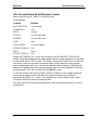
14.1 Compression
Barrier strip linking B-C and D-G (as factory set).
Initial settings.
Controls
Position
MODE SWITCH
Compress
THRESHOLD
Out
RATIO
4
ATTACK
-
RELEASE
Auto
GAIN
0dB
CHN BYPASS
In (Illuminated)
DE-ESS THRSHLD
Out
FREQ
-
PK LIM THRSHLD
Out
Rotate the THRESHOLD control anticlockwise until the BELOW THRESHOLD
meter is fully illuminated and an appropriate amount of gain is indicated on the
GAIN REDUCTION meter. This operation will be accompanied with a drop in
output level, as indicated by the OUTPUT METER. The output GAIN CONTROL
should now be adjusted to reinstate the output level. The levels of the
uncompressed input signal and the compressed output signal can now be
compared on the output meter by operating the METER INPUT switch.
Final adjustments of the controls can then be made to suit particular requirements,
including the RATIO, ATTACK, and RELEASE controls. The 'auto' position of the
release control provides for a program related operation of the dynamics of the
unit, and will be accepted for most general purpose applications. Should a tighter
or looser requirement be necessary, then both the attack and release controls can
be set individually to suit.
The experienced engineer will be able to set the compressor controls to near
optimum position for any source material with the BYPASS switch out, so that the
compressor can be 'dropped' into a live performance without disturbance.
14.2 De-essing
The DPR-402 has three modes of de-essing available, de-ess wide with
simultaneous compression, de-ess wide with full dynamic control, and de-ess HF
Page 20
BSS Audio
DPR-402 User Manual v3.0
with full dynamic control. De-ess wide attenuates with whole frequency spectrum,
and although acceptable for most vocal sources, it may cause undesirable side
effects on a mixed program source (refer to section 12.2; Broadband De-essing
and controls and 12.3; HF Only De-essing and Controls). De-ess HF only
attenuates the high frequencies and therefore produces superior results in all cases,
which is essential when de-essing a mixed program source.
If simultaneous de-ess HF and compression are required, the separate channels
must be used for each function.
14.3 De-essing Wide with Simultaneous Compression
Barrier strip linking B-C and D-G (as factory set).
Initial settings.
Set all compressor controls as required (refer to section 14.1; Compression). For
optimum de-essing effect, no more than 10-15dB of compression should be used. If
compression is not required, then set THRESHOLD to OUT.
Controls
Position
DE-ESS THRSHLD
OUT
FREQ
4kHz
PK LIM THRSHLD
OUT
Under program control, gradually rotate the DE-ESS THRESHOLD control
anticlockwise until the required effect is achieved. The FREQ control can also be
adjusted to ensure that frequencies lower than those causing concern do not
initiate de-essing. It should be remembered that this de-essing is wideband and
may cause distortion or pumping effects if the source program contains significant
low frequencies.
Page 21
BSS Audio
DPR-402 User Manual v3.0
14.4 De-ess Wide with Full Dynamic Control
Barrier strip linking B-C and D-G (as factory set).
Initial settings.
Controls
Position
MODE SWITCH
De-ess wide
THRESHOLD
Out
RATIO
Infinity
ATTACK
50 microseconds
RELEASE
100 milliseconds
GAIN
0dB
CHN BYPASS
In (Illuminated)
DE-ESS THRSHLD
Out
FREQ
4kHz
PK LIM THRSHLD
Out
Rotate the THRESHOLD control anticlockwise until the BELOW THRESHOLD
meter is fully illuminated and an appropriate amount of gain reduction is indicated
on the GAIN REDUCTION meter. The FREQ control and THRESHOLD control can
now be fine tuned to achieve the desired effect whilst listening to the program.
Gain compensation will not normally be required when de-essing. Although fast
attack and release times are most appropriate, they should be adjusted to achieve
the best results. The 'auto' position should NOT be used.
To aid the correct setting of the FREQ control in relation to the audible sibilance,
the source program can be listened to through the internal de-ess filter by
depressing the MON S.C. switch. This replaces the normal signal at the output
connector with the output of the de-ess filter.
The peak limiter can be used simultaneously with wide band de-essing, should it
be required.
Page 22
BSS Audio
DPR-402 User Manual v3.0
14.5 De-ess HF with Full Dynamic Control
Barrier strip linking B-C and D-G (as factory set).
Initial settings.
Controls
Position
MODE SWITCH
De-ess wide
THRESHOLD
Out
RATIO
Infinity
ATTACK
50 microseconds
RELEASE
100 milliseconds
GAIN
0dB
CHN BYPASS
In (Illuminated)
DE-ESS THRSHLD
Out
FREQ
4kHz
PK LIM THRSHLD
Out
Rotate the THRESHOLD control anticlockwise until the BELOW THRESHOLD
meter is fully illuminated and an appropriate amount of gain reduction is indicated
on the GAIN REDUCTION meter. The FREQ control and THRESHOLD control can
now be fine tuned to achieve the desired effect whilst listening to the program.
Gain compensation will not normally be required when de-essing. Although fast
attack and release times are most appropriate, they should be adjusted to achieve
the best results. The 'auto' position should NOT be used.
To aid the correct setting of the FREQ control in relation to the audible sibilance,
the source program can be listened to through the internal de-ess filter by
depressing the MON S.C. switch. This replaces the normal signal at the output
connector with the output of the de-ess filter.
The peak limiter should NOT be used in the HF mode.
Page 23
BSS Audio
DPR-402 User Manual v3.0
14.6 Peak Limiting
The peak limiter is designed to be used in conjunction with compression and/or
any wide band de-essing. It should not be used simultaneously with HF de-essing
or when external filters are patched into the SUBTRACT side chain (Terminal G).
Barrier strip linking : D-G (other links to suit functions as required).
Initial settings.
Controls
Position
PK LIM THRSHLD
As required
FAST/SLOW switch FAST
on rear panel
The PEAK LIMITER control is calibrated in dBv (ref 0.775v), and is set to suit the
headroom of following equipment. Should the red LED indicator remain on other
than for occasional peaks, the GAIN control should be backed off to reduce the
signal to the peak limiter. If this produces an unwanted decrease in overall output
level, then the amount of compression should be increased either by reducing the
compressor threshold, or by increasing the compressor ratio and then reinstating
the gain.
15 Applications using the Barrier Strip
15.1 Patching of External Equipment
Control Side Chain
A very common requirement is to make the threshold of the compressor frequency
conscious by inserting a graphic or parametric equaliser into the control side
chain. The input of the external equipment should be connected to one of the send
outputs of the unit, and the output of the external equipment connected to one of
the return inputs, as required. Care should be taken to avoid introducing earth
loops when the external equipment is mains powered, as all inputs and outputs on
the barrier strip are unbalanced. A signal 0v ground is provided at pins A and J for
connection to the screens of one or both of the connecting cables, as necessary.
All external equipment should be capable of operating at general line levels (Max
+20dBv), have unity gain, and have high input impedance (>10k) and a low output
impedance (>1k).
In order to preserve the THRESHOLD control calibration, it is essential that
unwanted frequencies are attenuated rather than wanted frequencies boosted by
the external filter. For example, if compression is to be controlled by a narrow midband of frequencies, then the low frequency and high frequency sliders should be
pulled down, and the mid-band sliders left at 0dB.
Page 24
BSS Audio
DPR-402 User Manual v3.0
Subtracting Side Chain
Inserting an external equaliser into the subtract side chain has the effect of
modifying the tonal balance of the processed signal by adding or subtracting a
specific band of frequencies. The external equipment should meet all the
requirements specified in the control side chain section (above) and be operated in
a similar manner. The adding or subtracting process requires that all signals are
appropriately phased and the gain be unity. Any errors may lead to unexpected
results.
For the units DE-ESS HF function, the internal filters have been phase and
amplitude corrected to achieve the required response.
15.2 Repatching of the Barrier Strip for other uses and Special Effects
The following table lists many of the possible uses of the DPR-402. This is not an
exhaustive list, and other combinations may be tried. To obtain the full benefits of
its versatility, a simple understanding of how it works is required (refer to section
13; Rear Barrier Strip).
MODE
NORMAL COMPRESSION
SUBTRACT
S/C LINK
CONTROL
S/C LINK
D-G
C-B
D-G
F-B
F-G
F-B
D-G
E-B
E-G
E-B
Compression occurs equally at all frequencies.
H.F. RE-EMPHASISED COMPRESSION
Compression is higher at LOW frequencies. This
arrangement will make heavily compressed signals
sound brighter as it lessens the effect of heavy low
frequencies modulating the treble.
H.F. RE-EMPHASISED COMPRESSION
As above, but more pronounced.
L.F. RE-EMPHASISED COMPRESSION
Compression is higher at HIGH frequencies. This is
useful for controlling harsh or shrill components of a
signal, allowing faster ATTACK and DECAY to be
used before LF distortion becomes a problem.
L.F. RE-EMPHASISED COMPRESSION
Compression is higher at HIGH frequencies. This is
useful for controlling harsh or shrill components of a
signal, allowing faster ATTACK and DECAY to be
used before LF distortion becomes a problem.
Page 25
BSS Audio
MODE
DPR-402 User Manual v3.0
SUBTRACT
S/C LINK
CONTROL
S/C LINK
D-G
L-B
K-G
L-B
EXPANDER - WIDE BAND
C-G
D-B
When input signals exceed the set threshold,
expansion occurs, since the subtract side chain signal
is added to the main signal. The DE-ESSER should not
normally be used in this mode. The PEAK LIMITER
may be used for effect.
H-J
EXPANDER - L.F. ONLY
K-H
L-B
D-H
L-B
D-H
C-B
EXTERNAL GAIN CONTROL
D-G
EXT SIG
By driving the control s/c with an external signal, the
amplitude of the main signal will be modulated by
the envelope of the external control signal. By
choosing links on the subtract s/c, modulation can be
wide band or L.F. only. DE-ESS and PEAK LIMITER
should not be used in this mode.
K-G
WIDE BAND L.F. CONTROL COMPRESSION
This mode compress the entire audio spectrum under
control of the frequencies below that set by the FREQ
control. The modulation of H.F. signals by the L.F.
signals is an effect which may be desired.
NARROW L.F. CONTROL COMPRESSION
Only frequencies below that set on the FREQ control
are compressed. Low frequencies are compressed
without modulating the high frequencies, which pass
unattenuated. The PEAK LIMITER and DE-ESSER
should not normally be used in this mode.
As above, but only those frequencies below that set
by the FREQ control are expanded.
EXPANDER - L.F. CONTROL. (MODE switch to
COMPRESS)
EXPANDER - H.F. CONTROL. (MODE switch to DEESS WIDE)
As in wide band, expansion occurs over the entire
audio bandwidth. However, it is under the control of
either low or high frequencies, as set by the links and
FREQ control.
Page 26
BSS Audio
DPR-402 User Manual v3.0
MODE
SUBTRACT
S/C LINK
CONTROL
S/C LINK
AMPLITUDE CONTROLLED MIXING (1)
EXT SIG to
G
C-B
EXT SIG to
G (sum)
EXT SIG to B
(control)
In this mode, an external signal will be summed with
the main signal and appear on the compressor, under
control of the amplitude of the main signal. Wide
band link C-B, L.F. only link K-B, H.F. only link C-B
and MODE switch to DE-ESS WIDE.
AMPLITUDE CONTROLLED MIXING (2)
As above, but the external signal will be summed
with the main signal, but this time under control of
the same, or another, external control input.
K-B
These two modes may be used to good effect when the external signal is an echo
return or delayed signal. For example, a single voice can be automatically
chorused above the set threshold.
15.3 Stereo Linking
When stereo signals are compressed, it is necessary for the gain of both channels of
the compressor to be identical at any moment in time, otherwise the stereo image
will move around the sound picture as the relative levels of the left and right hand
signals vary. Stereo linking couples together the compressor control signals, so that
the VCAs in both channels work together, as in a stereo fader.
It should be noted however that, when in stereo linked mode, the standard DE-ESS
and PEAK LIMITER functions continue to operate independently for each channel,
and are not part of the stereo linking.
There are three possible ways to stereo link of the DPR-402:
Stereo Link Switch
When the rear panel STEREO LINK switch in ON, both channels are couples
together, and the LINK LED illuminates on the front panel.
In this mode, it is important that the compressor controls are set identically for both
channels.
Hard Wired Stereo and Multiple Channel Linking
The stereo coupling point is available at connection M on the BARRIER STRIP, and
up to four channels may be coupled together by simply strapping these pins
together. Screened cable will not normally be required if the wiring is short, unless
there are strong local interference fields present.
Page 27
BSS Audio
DPR-402 User Manual v3.0
In this mode, it is important that the compressor controls are set identically for all
channels.
Improved Stereo Coupling
In this mode, only the controls on Channel 1 compressor will be required to
control both channels, as the control signal for channel 1s VCA is used to drive
that on channel 2. This gives excellent stereo matching without the need to adjust
both sets of compressor controls. Two 10k ohm, ¼ watt, 1% resistors are required
to sum the left and right signals into channel 1 CONTROL S/C RETURN input.
Page 28
BSS Audio
DPR-402 User Manual v3.0
16 Warranty Information
When sold to an end user by BSS Audio or a BSS Audio Authorised Reseller, this
unit is warranted by the seller to the purchaser against defects in workmanship and
the materials used in its manufacture for a period of one year from the date of sale.
Faults arising from misuse, unauthorised modifications or accidents are not
covered under this warranty. No other warranty is expressed or implied.
If the unit is faulty it should be sent to the seller of the equipment, in its original
packaging with shipping prepaid. The unit will be returned to you when the repair
has been completed. If the unit was purchased in the European Union, you may, as
an alternative, return the unit to any other BSS distributor in the European Union.
You should include a statement listing the faults found. The unit’s serial number
must be quoted in all correspondence relating to a claim.
We recommend that you record your purchase information here for future
reference.
Dealer Name:
Dealer Address:
Post/Zip Code:
Dealer Phone No.:
Dealer Contact Name:
Invoice/Receipt No.:
Date of Purchase:
Unit Serial Number:
In keeping with our policy of continued improvement, BSS Audio reserves the right
to alter specifications without prior notice.
The DPR-402 was designed and developed by BSS Audio, Hertfordshire, England.
Phone (+44) (0)1707 660667. Fax (+44) (0)1707 660755.
World Wide Web address: http://www.bss.co.uk
Page 29
BSS Audio
DPR-402 User Manual v3.0
17 Specifications
17.1 General
Input Impedance:
10k ohm balanced or unbalanced.
Input Headroom:
>+20dBv.
Input CMMR:
Better than -50dB 30Hz-20kHz. Typically -65dB at
1kHz.
Output level:
>+20dBv into 600 ohms or greater.
Output Impedance:
<1 ohm unbalanced.
Output Gain:
±20dB continuously variable.
Frequency Response:
±1dB 25Hz to 20kHz. Ultrasonic filter -3dB at 30kHz.
Noise:
Equivalent input noise <-86dBv 22Hz to 22kHz
<-82dBv CCIR weighted.
Distortion:
Unity Gain +10dBm output, below threshold.
THD. <0.03% 20Hz-20kHz. Typically 0.002% at
1kHz.
IMD. <0.01% SMPTE. Typically 0.003%.10dB
compression.
Threshold 0dB. 1kHz, 5sec rel. Time (see note 1).
2nd Harmonic <0.15%.
3rd Harmonic <0.05%.
IMD (SMPTE) <0.25%.
Cross Talk:
Better than -85dB 20Hz to 20kHz, any settings.
17.2 Compressor
Threshold Range:
-30dBv to 20dBv continuously variable.
Compressor Ratio:
1:1 to infinity:1 continuously variable. Over infinity
available by Barrier strip re-linking.
Maximum VCA Range:
>30dB.
Attack Time:
50 microseconds to 80 milliseconds in 11 switched
steps (see note 2).
Release Time:
5 milliseconds to 5 seconds in 10 switched steps and
AUTO (see note 2).
AUTO TIME Constant:
A two part program dependant time constant. Attack
time is typically 200 microseconds on fast transient
overdrives. Release is typically 10 milliseconds for
Page 30
BSS Audio
DPR-402 User Manual v3.0
63% recovery from a 10dB 4 millisecond overdrive,
and 1 second for a 10dB 40 millisecond overdrive.
17.3 De-esser
Threshold Range:
-30dBv to 20dBv continually variable.
Ratio:
Infinite, at and above twice the set frequency.
Frequency Range:
700Hz to 20kHz continuously variable (see note 3).
17.4 Peak limiter
Threshold Range:
+4dBv to +20dBv continuously variable.
Ratio:
>20:1.
Attack Time:
150 microseconds, fast setting.
750 microseconds, slow setting.
Release Time:
100 milliseconds, fast setting.
500 milliseconds, slow setting.
17.5 Notes
Note 1:
Harmonic distortion will increase with reduced
frequency and shorter time constants, which is inherent
in this type of equipment.
Note 2:
Attack times are those as measured to achieve 63% of
final gain reduction with a step signal of 8dB above
threshold. Release times are those as measured to
achieve 63% recovery of open gain or removal of a
signal of 8dB above threshold.
Note 3:
The frequency is that at which 3dB of gain reduction
occurs for 10dB of signal overdrive above threshold.
10dB of gain reduction will occur at and above twice
this frequency.
17.6 Facilities
Mode Switch:
3 position switch to select:
Bypass Switch:
Normal mode to allow simultaneous wide band deessing, compressing and peak limiting.
MON S.C. Switch:
Wide band de-ess mode utilising compressor side
chain.
Meter Input Switch:
HF de-ess mode utilising compressor side chain.
Page 31
BSS Audio
DPR-402 User Manual v3.0
Bypasses all functions of the unit at unity gain, allowing
all parameters to be adjusted and levels checked whilst
'on air'.
Momentarily connects the control side chain to the
output of the unit to allow monitoring of control insert
return.
Momentarily connects the input signal to the output
level meter to allow comparison of input and output
levels prior to operating the bypass switch.
Metering:
BELOW THRESHOLD: 5 LEDs to indicate side chain
level from 18dB to 0dB ref the set threshold.
GAIN REDUCTION: 9 LEDs to indicate the amount of
gain reduction from 3dV to 27dB. Display 'bright-up' at
30dB of reduction.
OUTPUT: 12 LEDs to indicate output level from 24dBm to +18dBm. Display 'bright-up' at +21dBm
(clip).
DE-ESS: 2 LEDs to indicate normal and hard de-essing.
PEAK LIMITING: 2 LEDs to indicate normal and hard
peak limiting.
Stereo Switch
(Rear Panel):
Couples channel 1 and channel 2 control signals for
stereo operation. Indicated on the front panel by an
LED.
Rear Connections:
INPUT: XLR 3-31 or equivalent (Balanced)
OUTPUT: XLR 3-32 or equivalent (Unbalanced)
ACCESS POINTS: Barrier strip, providing control and
subtract side chain insertion points including HP and
LP filter sends, pre-emphasis and de-emphasis network
sends; inverse phase sends for expander mode; and
control side chain DC access point for stereo, quad
etc., coupling and gating.
Power:
Switch selectable 120V or 240V, 50/60Hz, 15VA. AC
fuses on the rear of the unit. DC fuses located inside the
unit.
Mounting requirements:
(Ht x W x D)
44.5mm x 483mm x 229mm
1U/1¾" x 19 x 9"
Weight:
4.5kg (Packed)
Page 32