1
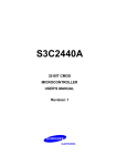
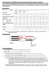
Liao Lijuan
COMPUTER MODELLING & NEW TECHNOLOGIES 2014 18(11) 415-418
Design of real-time clock based on ARM embedded system
Lijuan Liao*
College of Computer Science and Technology, Taiyuan University of Technology, 030024, China
Received 1 March 2014, www.cmnt.lv
Abstract
Real-time clock of ARM processor has disadvantages such as dependence on the processor, low interrupt level and unadjustable
accuracy. Linux embedded system based on ARM processor is provided with independent real-time clock using X1227 real-time clock
chip. In addition, the work presents transplant of uCLinux system in S3C2440A, procedure of system boot loader and frame of Linux
character device driver, thus achieving design of RTC driver based on I2C protocol of uCLinux system.
Keywords: S3C2440A, RTC, X1227
The real-time clock integrated in S3C2440A is
controlled by INT_RTC and INT_ADC, which have the
lowest priority in all the 26 interrupt sources. Besides, this
real-time clock is not universal, and cannot run with
support of 3.3V voltage and microprocessor. Therefore,
external RTC chip X1227 is applied.
1 Introduction
Real-time system (RTS) is that correct calculation depends
on logical validity of procedure and resulting time. If time
constraint of system is not satisfied, the system will go
wrong. Then real-time clock is applied to RTS. Software
counting can be used to realize function of real-time clock
by the timer in ARM processor. However, it is not
universal because of the disadvantages including data loss
after power down, low interrupt level, unadjustable
accuracy, etc. Real-time clock, with independent crystal
oscillator and power supply system, can constantly run,
thus providing reliable time for RTS and avoiding trouble.
By using I2C bus, X1227 real-time clock chip has wide
supply voltage range, high interrupt level and adjustable
accuracy, thus promoting achievement and correct
operation of RTS.
3 RTC chip X1227
3.1 INTERNAL STRUCTURE OF X1227
X1227 is a real-time clock with functions of
clock/calendar, CPU monitoring circuit and two-way
query and alarm. Dual port clock and alarm register can
ensure the accuracy of clock work, even during read and
write operation. Clock/calendar can be provided with
functions of controlling and reading by registers. Clock
can precisely display the time by the unit of second,
minute, hour, day, week, month and year using a 32.768
kHz crystal with low cost. There is a watchdog timer in
X1227. If the watchdog timer overtimes, the reset pin
RESET will be activated. X1227 has an input pin VBACK,
using a non-rechargeable battery as the back-up power. A
4K-bit EEPROM array in X1227, used as configuration
data memory, will be safe and not affected when the main
and standby power supplies lose efficiency. Figure 1
shows block diagram of X1227 consisting of control
registers, SRAM, EEPROM, I2C serial interface decoder,
status registers, standard crystal, watchdog timer, etc [2].
2 S3C2440A microprocessor
S3C2440A microprocessor of Samsung Corporation is
applied to embedded system using a new bus structure—
Advanced Micro controller Bus Architecture (AMBA).
The CPU is a 16/32-bit ARM920T RISC processor
designed by Advanced RISC Machines (ARM).
ARM920T has a cache architecture consisting of MMU,
AMBA BUS and Harvard. The architecture has
independent 16KB instruction and 16KB data caches
comprising eight-byte lines. S3C2440A is provided with a
complete set of common system peripherals to reduce cost
of the whole system and additional components [1].
* Corresponding author e-mail: [email protected]
415
Information and Computer Technologies
Liao Lijuan
COMPUTER MODELLING & NEW TECHNOLOGIES 2014 18(11) 415-418
FIGURE 1 Block diagram of X1227
3.2 MAIN FUNCTIONS OF X1227
4 Transplant of uclinux system to S3C2440A
RTC of X1227 uses a external quartz crystal with a
frequency of 32.768 kHz to keep accuracy of year, month,
day, week, hour, minute and second. RTC, with century
byte, can adjust leap years, the months less than 31 days,
and the form of time by one bit. After format conversion,
data of CCR in form of BCD code should be read and
written by I2C interface in X1227. There are two alarm
registers in X1227. If the time set by alarm register is the
same with RTC, the corresponding position of SR register
in CCR will be set to 1, thus realizing timing alarm. There
are four KEEPROMs in X1227. They will be used to store
key data of self-check program and system when system is
power off. WatchDog can be set to control the shortest
time of feeding the dog by writing WD1, WD0 of BL
register in CCR. When the procedure comes into endless
loop because of external disturbance, and timing register
reaches maximum, WatchDog will emit a signal to reset
SCM, thus the procedure is in control again.
X1227 is connected with S3C2440A using I2C
interface (See Figure 2). Serial data pin (SDA), as a bi-pin
connected with external 330Ω pull-up resister, is used to
input and output data to the device. Input of serial clock
pin (SCL) is used to time the whole data of input and
output devices, thus providing serial clock signals of data
transmission. VCC and VBACK inputs are received by the
power control circuit of X1227. If VCC< VBACK-0.2V,
then the power will be switched to VBACK by the power
control circuit; if VCC>VBACK, then it will return to
VCC.
4.1 UCLINUX SYSTEM
Uclinux (micro-control linux), as a Linux system in microcontrol field, is a major product of Lineo Corporation and
a model for embedded Linux of open source. Aiming at the
target processor of embedded system without MMU
(Memory Management Unit), uclinux is designed and
successfully transplanted to platforms. The users of
uclinux operation system can apply the whole Linux API
functions based on GNU general license. After clipping
and optimization, uclinux forms an embedded Linux with
high optimization and compact codes. Uclinux has
advantages such as small size, stability, good transplant,
excellent network function, perfect support to all the file
systems and abundant API functions. Therefore, uclinux
has good compatibility with Linux. API functions of
uclinux, except fork(), are the same as those of standard
Linux [3].
4.2 ESTABLISHMENT OF CROSS-COMPILING
ENVIRONMENT
Cross-compiling environment used for target machine is
established in PC because of limited storage of common
embedded system. The executable files, got from
compilation, connection and location of procedure in PC,
are loaded to the target machine through serial port. Crosscompiling environment is required to establish kernel
header files, binutils, bootstrap gcc, glibc, etc. The work
applies the method as follows. Firstly, GCC is installed in
PC aiming at compiler of ARM (arm-elf-gcc). Secondly,
the configured cross tool chain "arm-elf-tools20040427.sh" provided in "www.uclinux.org" is
convenient to use. In the root directory, after adding the
executed authority by running command "#chmod 755
arm-elf-tool-20040427.sh", the script can be operated to
install cross tool chain in correct position. At last, the
address "/user/local/bin" is checked to identify whether the
compiling environment file started with "arm-elf-" is
existed or not. If so, then cross-compiling environment
VCC
VCC
R1
330
X1227
3. 3V
1
2
3
4
VBack
VCC
X1
X2
SCL
SDA
VSS
RE SET
8
7
6
5
GPE 14
GPE 15
RE SET
S3C2440A
32. 768k
FIGURE 2 X1227 connected with S3C2440A
416
Information and Computer Technologies
Liao Lijuan
COMPUTER MODELLING & NEW TECHNOLOGIES 2014 18(11) 415-418
struct file_operations {
ssize_t(*read)(struct file *, char *, size_t, loff_t *);
sszie_t(* write)(struct file *, const char *,size_t, loff_t *);
int(* ioct1)(struct inode *, struct file *, unsigned int,Unsigned
long);
int(* open)(struct inode *, struct file *);
int(* release)(struct inode *, struct file*);
...};
will be successfully installed. The program above is
actually procedure of establishing uclinux library file.
5 Driving X1227 in unlinux system
5.1 SYSTEM BOOTSTRAP ROUTINE
BOOT, as the first running line of code in the chip after
power on, is applied to initialize running environment of
hardware and software in system for application program
operation. System bootstrap routine boots up operation
system and hands the control power over to operation
system core. This operation depends on the type of CPU
core and the resource applied to develop embedded system
software in CPU chip. Figure 3 shows the flow of system
boot loader based on this chip and application program.
The driver should realize the following functions:
1) open( )
Initialize the devices supported by the driver.
2) release( )
Close the devices supported by the driver after use.
3) read( )
Read data from character devices by application
program or Linux.
4) write( )
Write multiple byte data to character devices.
5) ioctl( )
Provide application program with some special
operation which cannot be easily realized by read() and
write() methods.
The above methods derive the functions as follows:
initialization, load and release of hardware devices;
management of equipment including setting real-time
parameter and providing unified operation interface for
devices; reading data of device files obtained from (or
responding to) application program; detecting or
processing device errors.
Reset
Setup entrance pointer of a program
Set the interrupt vector table
Initial various Peripherals In the chip
Initial object board
Initial different patterns of stack and
registers in CPU
5.3 DESIGN OF X1227 DRIVER
Call the main program
X1227 can communicate with ARM by I2C bus. Using
signal wires SCL and SDA, I2C bus can achieve data
interaction between devices, thus simplifying occupation
of hardware resources and PCB wiring space. I2C bus
realizes data transmission and command control by timing
signals including start, stop and ACK. If SCL is at the high
level and SDA switches from high to low level, I2C bus
will start sending signals; if SCL is at the high level and
SDA switches from low to high level, it will stop sending
signals; if the device receives 8-bit data, it will send ACK
to the sender. Then the sender will set SDA at the high
level, and the receiver will set SDA at the low level during
responsive clock pulse, thus achieving signal response.
Figure 4 shows start condition, stop condition and ACK of
I2C bus [5].
FIGURE 3 Flow of the system boot loader
5.2 DRIVER FRAMEWORK OF LINUX CHARACTER
DEVICE
X1227 as well as alarm clock is set and read by compiling
software. As a hardware device of system running in
Linux, X1227 is operated by drivers in Linux operation
system. The devices in Linux include character and block.
X1227 is a character device. Programs of user mode can
run character devices like common files. Therefore, the
driver of character device type should at least realize
system call functions including open(), release(), read()
and write(). In Linux kernel, X1227 character driver is
designed based on the framework as follows [4].
FIGURE 4 I2C bus
X1227 has slave device addresses including 1010
(access to 4KB EEPROM) and 1101 (access to CCR) used
to control RTC and WatchDog. Figure 5 shows operation
of a byte access including a slave address byte, an address
417
Information and Computer Technologies
Liao Lijuan
COMPUTER MODELLING & NEW TECHNOLOGIES 2014 18(11) 415-418
word (16 bits) to be accessed and an 8-bit operand. The last
bit of the slave address byte determines this operation. If
the last bit is 1, the reading will be conducted; if 0, writing
EEPROM
Write
START
Word Address 1
1 0 1 0
0
0 0 0 0 0 0 0
1 1 1
1 1 0 1
1
CCR
Read ACK
will be operated. The communication process of I2C bus
is simulated using I/O interface. Firstly, slave address of
I2C bus is defined to read and write devices by program.
Word Address 0
ACK
Data
ACK
STOP
ACK
FIGURE5 Access format of X1227
# define RTC_I2C_READ 0xaf //Read the address by I2C bus
# define RTC_I2C_WRITE 0xae // Write the address by I2C
bus
RTC driver module applies character devices achieved by
“struct file_operation” framework structure:
static struct file_operations x1227_fops = {
.owner = THIS_MODULE,
.ioctl = x1227_ioctl,
.open = x1227_open,
.release = x1227_release,
};
RdBy_Iic(0xd e,0x31 , &(rdata)) ; / / Read minute register
dbuf[1] = rdata;
…
RdBy_Iic(0xd e,0x35,&(rdata)) ; / / Read year register
dbuf[5] = rdata;
copy_to_user (buffer,dbu, f6) ; / / Change data from kernel to
user mode
…}
Function rtc_write() is mainly used to set time and date.
The compiled program can be re-compiled using crosscompiling tool of uclinux for operation in S3C2440A. In
Windows, uclinux kernel, root file system and executed
file are read and written through serial port of
hyperterminal. Basic settings are as follows: baud rate is
115200; data bit number 8; no parity checking; stop bit 1;
no data flow control.
In this structure, the whole functions are accomplished
by upper call function ioct1 [6]:
int x1227_ioctl(struct inode *inode, struct file *filp,
unsigned int cmd, unsigned long arg)
In the function, reading and writing transmission
commands of cmd are “RTC_RD_TIME” and
“RTC_SET_TIME”; arg is the structure pointer directing
to “struct rtc_time” for time storage. At first, the function
reads transmission command cmd to determine whether
the operation is writing or reading. If the result is reading,
then Function rtc_read() will be called to read data from
the register and keep them in arg; else if writing, then
Function rtc_write() will write data to the register.
Function rtc_read() can be used to read the time and
date in RTC register, achieved by the following function:
6 Conclusions
RTC is one of the typical applications of I2C in embeded
products. Even if there is no special I2C interface to
control processor chip, I2C bus time sequence will be
simulated by software to achieve communication between
chips with two I/O interface pins. Therefore, RTC is
suitable for embedded devices. The work aims at designing
driver of X1227 clock chip to achieve real-time clock
combined with RTC device driver model in uclinux. The
design realizes real time of system by replacing the
integrated clock in CPU. The designed clock has a good
performance in running and function, thus proving
practicability and stability of this driver design.
rtc_r ead (struct file * filep, cha r * buffer, size_t length)
{…
Init_Iic( ) ; / / Initialize I2C bus
RdBy _Iic( 0xde, 0x30, & (rdata) ) ; / / Read second register
dbu f[0] = rdata ;
References
[1] Samsung Electronics Co Ltd 2004 S3C2440A 32-BIT RISC
Microprocessor User’s Manual Korea Revision 0.12 Samsung
Electronics Co Ltd
[2] Intersil Corporation 2005 2-Wire RTC Real Time
Clock/Calendar/CPU Supervisor with EEPROM X1227 Datasheet
[EB/OL] http://www.intersil.com/
[3] Corbet J, Kroah-Hartman G, Rubini A 2005 Linux Device Drivers
3rd Edition O’Reilly 49-53
[4] Bovet D P 2002 Understanding the Linux Kernel 2nd Edition
O’Reilly
[5] Philips Semiconductors 2003 AN10216-01 I2C Manual 13-7
[6] Nilsson J, Rytterlund D 2000 “Modular Scheduling in Real-Time
Linux” MSc Thesis Department of Computer Engineering Idt
Malardalen University
Author
Lijuan Liao, born in September, 1963, Hengyang, Hunan Province, China
Current position, grades: associate professor in College of Computer Science and Technology, Taiyuan University of Technology, China.
Scientific interests: computer control and embedded technology.
Publications: 20 papers.
418
Information and Computer Technologies