1
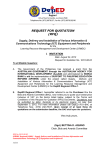
1394U User's Manual
1
Card Features
This chapter lists what you should find in the box, introduces the card’s features and
indicates the position of components you may need to know about. Please review this
chapter to familiarize yourself with the basic information about your 1394U card.
The 1394U card is for use with IBM-compatible personal computers.
Package Contents
Your card package should include the items listed here. If anything is missing or
damaged, please contact the vendor you bought the card from to resolve the problem.
You should find:
N
The 1394U card
N
This User's Manual
Main Features
This section has some general information about 1394 or “FireWire” technology and
features specific to the two models of the card.
1
What is IEEE 1394
The 1394 standard was defined, and continues to be maintained, by the Institute of
Electrical and Electronics Engineers, Inc. (IEEE). The technology allows for high-speed
connections between computers and related devices and helps bridge the divide between
computers and consumer electronics. The technology is flexible, easy to use and offers
high bandwidth at a low cost.
With 1394-compatible products and systems, users can transfer video or still images from
a camera or camcorder to a printer, PC, or television quickly, with no image degradation.
1394 Features
The 1394 standard is a high-speed serial bus designed to deliver high data transfer speeds
at a low cost, and with the low degree of latency required by a peripheral bus or by a
backup to a traditional parallel bus. Among its key features are:
N
N
N
N
N
N
N
N
High Speed. Speeds of 100, 200 and 400 megabits per second (Mbps) are currently
supported.
Isochronous Support. Deterministic bandwidth allocation guarantees bandwidth for
time-sensitive applications, such as real-time video feeds, that could otherwise be
disrupted by heavy bus traffic.
Flexible Topology. Devices can be daisy-chained and no central bus supervision is
required.
Hot-Plug Support. The bus is dynamically reconfigured whenever new nodes are
added, which means users don’t have to configure node IDs or unique termination
schemes.
Cable Power. Low-cost peripherals can be powered directly from the 1394 cable, so
no dedicated power supply is needed.
Open IEEE Standard. IEEE adoption has increased industry acceptance of the
standard.
Optimum Performance. Each cable connection can be up to 4.5 meters long,
yielding a total cable distance of 72 meters.
1394 End devices. IEEE 1394 interfaces have already been incorporated into a
variety of devices, including PC cameras, DV camcorders, DV recorders, digital still
cameras, high-speed hard disk drives, CD-ROM drives, DVD-ROM drives, DVDRAM drives, digital TVs, set-top boxes, scanners, and printers.
2
The 1394U and the PC System
The I394U is a host controller card with a PCI interface. It comes with three independent
IEEE1394 bus ports, each of which can transfer data at 400Mbps. When you plug an
IEEE 1394/FireWire device into one of the card’s three ports, Windows 98 will
automatically install the new device and the appropriate driver. With its hot-plug support,
you can easily connect or disconnect devices without having to first shut down your
computer. This enables true Plug-and-Play functionality.
D V D / CD
RO M
Ca m c o r d e r
DVD
Se t - t o p b o x
I3 9 4 b
Pr i n t e r
Sc a n n e r
Ca m e r a
St e r e o
PC System Requirements
1. A Pentium based PC (recommended) with one free PCI slot.
2. Windows 98 SE or above.
3. Any 1394 device that complies with either the 1394-1995 or 1394.a specification and
does not use more than 1.5 A.
3
2
Installation
This chapter explains how to install the card.
1394U Installation
To install the 1394U card, follow this procedure.
1.
2.
3.
4.
Make sure the computer is turned off.
Gain access to the interior of the PC.
Insert the 1394U card in an empty PCI slot.
Press the card gently but firmly into the slot and check to see that all contacts are
fully seated in the connector.
5. Attach the bracket screws that secure the card to the chassis.
6. Reinstall the covers on the PC.
7. Turn on the computer. Windows 98 will detect the addition of new hardware and
display the following message:
8. Click Next. Windows will then begin searching for a driver. The following message
will be displayed:
4
9. Keep the recommended option, to have Windows search for the driver, and click
Next. The following message will display:
10. Insert your Windows 98 installation CD into your CD-ROM drive. Select “CD-ROM
drive” and click Next.
11. Windows will search the CD for the appropriate driver and list what it finds. After it
has identified the appropriate driver, click “Next” to begin installation of the driver.
5
When the dialogue box below appears onscreen, the installation is finished. Click Finish
to complete setup. You will be instructed to reboot your computer.
12. After rebooting, click on the Device Manager tab in System Properties, which you
access from the Windows Control Panel. You should see an entry for the driver you
installed under the 1394 Bus Controller item. If the driver is not listed, please go back
to Step 1 and reinstall the card.
The Windows 98 installation CD includes the Texas 1394 OHCI driver, so you do not
need an installation CD or diskette. After the installation has finished and the computer
has rebooted, you may connect 1394/FireWire devices to it.
The first time you hot-plug a 1394 device into one of the host card ports, you will be
asked to insert your Windows 98 installation CD. However, you won’t need to insert the
CD to add additional 1394 devices; they should automatically appear in the Device
Manager after they are connected.
6
3
Using the Card
This chapter covers a few points on how to use the card once it is installed in your
computer system.
Connecting Devices
There are two ways to connect 1394/FireWire devices to the host card. Devices can
connect in serial in a “daisy chain” or through a repeater connected to one of the card
ports.
Daisy Chain Connections
When you connect devices in a daisy chain configuration you can connect up to 63
devices in a row. This scheme is simple and convenient, but has one drawback.
Since 1394/FireWire devices are “hot-pluggable,” you can connect and disconnect
devices while the computer is turned on. When you disconnect a device, the other
devices that come after it are temporarily disconnected until you reconnect them to the
chain.
The 1394/FireWire card supplies power to devices through the cable connection. This
power has some limitations. See the Power Considerations section later in this chapter
for more information.
Repeater Connections
If you use a 1394/FireWire repeater to connect devices to the card, all connected devices
are independent of each other. You can then disconnect any device without disturbing
the other devices connected to the card.
An additional feature of using a hub is that the repeater can also provide power for
devices that use more power than the 1394/FireWire cabling supplies. This allows
connecting one or more devices that use more power.
1394 Cabling
The 1394 standard has a maximum connection cable length of 4.5 meters (15 feet). This
means this is the maximum distance between devices.
If you need to connect two devices more than 4.5 meters apart, you can use a repeater to
extend the cable length between the devices.
7
Cable Types
There are two types of 1394/FireWire cable. One type, 6-pin to 6-pin, supplies power to
the device it connects to. The other type is 6-pin to 4-pin, for devices that are selfpowered and do not require power from the 1394/FireWire bus.
If you connect devices in a daisy chain and any device needs power from the cabling, all
cabling must be 6-pin to 6-pin. If you use a repeater, you can use either type.
Power Considerations
The 1394/FireWire bus provides limited electrical power through the connector cables, as
noted above. Some devices will have their own power supplies. Other devices may need
more power than is available from the bus and can be powered from a powered repeater.
Make sure to check the power requirements of any devices you plan to use before you
connect them. Consult the device documentation for this information and the connection
instructions.
8
4
Troubleshooting and Technical Information
This chapter has two sections, Troubleshooting and Technical Information. The
troubleshooting section covers some basic things you can do in the event that you
encounter problems using the card in your system. The Technical Information section has
information on the card specifications.
Troubleshooting
If the card and devices connected to it do not seem to be working properly check the
following:
1. Check that all cables are securely connected.
2. Check that the correct cables are in use. If a device requires power from the
1394/FireWire bus, 6-pin cabling must be used.
3. Make sure all devices are turned on.
4. Make sure the devices are getting the power they require.
5. If a powered repeater is connected, make sure it is turned on.
6. If the devices are connected in a daisy chain and you have problems after
disconnecting a device, please reconnect the device. Normally, the device will be
enabled. If not, please restart the computer and see if the problem clears up.
7. Make sure there isn’t a problem with the card installation. If your I394U card doesn’t
work properly, please check the card’s status in the Device Manager. If there is an
exclamation mark beside the device, then shutdown the computer, open the system,
and ensure that the card is fully and firmly seated in the slot connector. Reinstall the
system covers and power on the computer. If the exclamation mark still displays,
please contact your vendor.
Technical Information
Output
1394 R/A flat connector X3
Operating System
Windows 98 SE, Windows ME, or Windows 2000
Serial Bus
3-port PHY layer connector and interface
400 Mbps max transfer rate (50 MB/sec max)
63 (4-pin or 6-pin) computer and consumer device connections
Protocol
Asynchronous and isochronous data transfer supported
Real-time critical applications (digital video) supported
Non real-time applications (printers, scanners) supported
9
Topology
Both tree and bus topology supported
64-bit device addressing
Can be accessed with processor-to-memory transactions
Board Size
120 mm x 65 mm
10