1
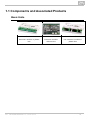
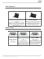
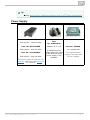
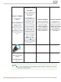
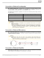
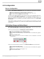
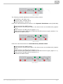
2N® Helios IP Audio Kit
IP Intercom Module
Installation Manual
Version
2.3
www.2n.cz
The 2N TELEKOMUNIKACE a.s. is a Czech manufacturer and supplier of telecommunications
equipment.
The product family developed by 2N TELEKOMUNIKACE a.s. includes GSM gateways, private
branch exchanges (PBX), and door and lift communicators. 2N TELEKOMUNIKACE a.s. has
been ranked among the Czech top companies for years and represented a symbol of
stability and prosperity on the telecommunications market for almost two decades. At
present, we export our products into over 120 countries worldwide and have exclusive
distributors on all continents.
2N® is a registered trademark of 2N TELEKOMUNIKACE a.s. Any product and/or other
names mentioned herein are registered trademarks and/or trademarks or brands protected
by law.
2N TELEKOMUNIKACE a.s. administers the FAQ database to help you quickly find
information and to answer your questions about 2N products and services. On
www.faq.2n.cz you can find information regarding products adjustment and instructions for
optimum use and procedures „What to do if...“.
2N TELEKOMUNIKACE a.s. hereby declares that the 2N ® Helios IP Audio Kit product
complies with all basic requirements and other relevant provisions of the 1999/5/EC
directive. For the full wording of the Declaration of Conformity see the CD-ROM (if
enclosed) or our website at www.2n.cz.
The 2N TELEKOMUNIKACE a.s. is the holder of the ISO 9001:2009 certificate. All
development, production and distribution processes of the company are managed by this
standard and guarantee a high quality, technical level and professional aspect of all our
products.
Content
Content
1. Product Overview . . . . . . . . . . . . . . . . . . . . . . . . . . . . . . . . . . 4
1.1 Components and Associated Products . . . . . . . . . . . . . . . . . . . . . . . . . . . . . . . 6
1.2 Terms and Symbols . . . . . . . . . . . . . . . . . . . . . . . . . . . . . . . . . . . . . . . . . . . . . . 12
2. Description and Installation . . . . . . . . . . . . . . . . . . . . . . . . . . 13
2.1 Before You Start . . . . . . . . . . . . . . . . . . . . . . . . . . . . . . . . . . . . . . . . . . . . . . . . . 14
2.2 Mechanical Installation . . . . . . . . . . . . . . . . . . . . . . . . . . . . . . . . . . . . . . . . . . . . 15
2.3 Electric Installation . . . . . . . . . . . . . . . . . . . . . . . . . . . . . . . . . . . . . . . . . . . . . . . 17
2.5 Configuration . . . . . . . . . . . . . . . . . . . . . . . . . . . . . . . . . . . . . . . . . . . . . . . . . . . 24
2.4 Extending Module Connection . . . . . . . . . . . . . . . . . . . . . . . . . . . . . . . . . . . . . . 26
3. Technical Parameters . . . . . . . . . . . . . . . . . . . . . . . . . . . . . . . 29
4. Supplementary Information . . . . . . . . . . . . . . . . . . . . . . . . . . 32
4.1 Troubleshooting . . . . . . . . . . . . . . . . . . . . . . . . . . . . . . . . . . . . . . . . . . . . . . . . . 33
4.2 Directives, Laws and Regulations . . . . . . . . . . . . . . . . . . . . . . . . . . . . . . . . . . . 34
4.3 General Instructions and Cautions . . . . . . . . . . . . . . . . . . . . . . . . . . . . . . . . . . . 35
1. Product Overview
Here is what you can find in this section:
1.1 Components and Associated Products
1.2 Terms and Symbols
Basic Features
2N® Helios IP Audio Kit is a universal and reliable IP intercom module designed for
integration in the third parties' equipment. It is provided with a number of useful
functions that are not quite common in the devices of this category. Featuring the SIP
standard support and compatibility with renowned IP exchange and telephone
manufacturers, 2N® Helios IP Audio Kit can make use of all VoIP services available
on the market.
2N® Helios IP Audio Kit is equipped with a 10 W power amplifier for external
loudspeaker connection. If the power output of amplifier is insufficient for your specific
application, you can connect an external power amplifier to the line output. You can
also connect an external electret microphone or another audio signal source to the IP
intercom line output.
2N® Helios IP Audio Kit allows up to 16 separate buttons or a 16-button matrix
keypad to be connected. Set the button function flexibly according to your specific
application needs. You can set up to three telephone numbers and call time profiles to
each of the buttons to make the called subscriber accessible any time. Configure the
buttons as a numerical keypad, which can be used as a switch activation code lock or
for dialling a preset or any other telephone number.
2N® Helios IP Audio Kit is equipped with one relay output and two active 12 V
outputs. Use the numerical keypad or, during the call, any telephone to control these
outputs. A wide range of output mode settings help you make use of a high number of
applications.
2N® Helios IP Audio Kit is equipped with two galvanically isolated digital inputs and
three status signalling outputs.
2N® TELEKOMUNIKACE a.s., www.2n.cz
4
2N® Helios IP Audio Kit is very easy to install. All you have to do is connect it to
your LAN using the LAN cable. An integrated two-port LAN switch simplifies installation
on sites with a limited LAN infrastructure. Supply the intercom either from a 9–36 V
source or directly from your PoE supporting LAN.
Use a PC web browser to configure your 2N® Helios IP Audio Kit . Apply the IP
Manager to administer extensive intercom installations easily and quickly.
Advantages of Use
Industrial design and variable mounting options
Wide supply power range + PoE supply
Integrated 10 W power amplifier
External amplifier connection
External microphone/audio signal source connection
Galvanically isolated relay output
Two controlled active 12 V outputs
Two galvanically isolated logic inputs
Up to 3 signalling LED outputs
Up to 16 external buttons/matrix keypad connection
Integrated two-port LAN switch
Bidirectional communication – acoustic echo cancelling
Configuration via web interface/special PC application
SIP 2.0 support
HTTP(S) server for configuration
SNTP client for server time synchronisation
RTSP server for audio streaming
TFTP client for automatic configuration and firmware update
2N® TELEKOMUNIKACE a.s., www.2n.cz
5
1.1 Components and Associated Products
Basic Units
Part No. 9154100
Part No. 9154101
Part No. 9154102
Intercom module in plastic
box
Intercom module
without box
Lite intercom module in
plastic box
2N® TELEKOMUNIKACE a.s., www.2n.cz
6
Internal Units
Part No. 91378365
Part No. 91378365WH
2N® Indoor Touch black
2N® Indoor Touch white
The elegant internal touch
The elegant internal touch
®
panel,
2N® Indoor Touch
panel, 2N Indoor Touch
, is suitable for all 2N®
, is suitable for all 2N®
Helios IP intercoms. On
Helios IP intercoms. On
the panel’s display not only the panel’s display not only
can you find out who is at
can you find out who is at
the door, but also start a
the door, but also start a
conversation with the
conversation with the
visitor, open the lock or
visitor, open the lock or
turn on the light in the
turn on the light in the
entrance hall.
entrance hall.
Part No. 91378366
Part No. 91378367
Part No. 91378368
2N® Indoor Touch black
2N® Indoor Touch black
2N® Indoor Touch black
WiFi
WiFi + NFC
NFC
The elegant internal touch
The elegant internal touch
The elegant internal touch
®
®
panel, 2N Indoor Touch panel, 2N Indoor Touch panel, 2N® Indoor Touch
, is suitable for all 2N®
, is suitable for all 2N®
, is suitable for all 2N®
Helios IP intercoms. On
Helios IP intercoms. On
Helios IP intercoms. On
the panel’s display not only the panel’s display not only the panel’s display not only
can you find out who is at
can you find out who is at
can you find out who is at
the door, but also start a
the door, but also start a
the door, but also start a
conversation with the
conversation with the
conversation with the
visitor, open the lock or
visitor, open the lock or
visitor, open the lock or
turn on the light in the
turn on the light in the
turn on the light in the
entrance hall.
entrance hall.
entrance hall.
2N® TELEKOMUNIKACE a.s., www.2n.cz
7
VoIP Telephones
Part No. 91378357
Grandstream GXV3240 VoIP video
telephone
GXV3240 is the successor to the popular
GXV3140 model, which allows comfortable
video calls in the IP network. Touchscreen
and keyboard control.
Part No. 91378358
Grandstream GXV3275 VoIP telephone
GXV3275 is the successor to the
popular GXV3175 model, which allows
comfortable video calls in the IP
network. Touchscreen control.
Electric Locks
Part No. 932080E
Part No. 932070E
BEFO 1211
12 V / 600 mA
2N® TELEKOMUNIKACE a.s., www.2n.cz
BEFO 1221 with momentum
pin
12V / 600 mA
For opening of the lock a
short electrical impuls is
sufficient, which unlocks the
lock. Lock is then open until
someone closes the door.
Part No. 932090E
BEFO 1211MB
12V / 600 mA.
Enables mechanically close or
open the lock. When opened,
the lock is open all the time.
When closed, it behaves as
standart electrical lock.
8
Tip
FAQ: Electric locks - Difference between locks in 2N® Helios IP accesories
Power Supply
Part. No. 91378100
PoE injector - without cable
Part. No. 91378100E
PoE injector - with EU cable
Part. No. 91378100US
PoE injector - with US cable
Part
No. 91341481E
Adapter 12 V / 2 A
A stabilised power
supply has to be used
if the Ethernet (PoE)
power supply is not
available.
Part No. 932928
12 V transformer
For external power
supply of the lock with
12V AC voltage.
For power supply of intercom via
ethernet cable when PoE switch is
not available.
2N® TELEKOMUNIKACE a.s., www.2n.cz
9
Additional Modules
Part No. 9159010
Part No. 9137410E
Security Relay
External IP Relay - 1
A handy add-on that
output
significantly enhances
door entry security as Standalone IP device
it prevents tampering
which can be
with the intercom
controlled by HTTP co
and forced opening of
mmands sent by
the lock. To be
Helios IP intercom,
installed between
which can thus control
intercom and lock,
devices on unlimited
powered by the
distance.
intercom.
2N® TELEKOMUNIKACE a.s., www.2n.cz
Part No. 9137411E
External IP Relay - 4
outputs, PoE
Part No. 9159013
Exit button
Standalone IP device
which can be controlled
by HTTP commands
sent by Helios IP
intercom, which can
thus control devices on
unlimited distance.
A button for
connection to a logic
input for opening a
door inside a building
10
Part No.
9159014EU/US/UK
2N® 2Wire
Part No. 9159012
(set of 2 adaptors and
power source for
EU/US/UK)
The 2N® 2Wire conv
erter allows you to
Part No. 9154001
use existing wiring (2
wires) from your
Electret microphone
Set for installation on
original door bell or
with self-adhesive layer.
a door, enabling the
door intercom to
status of door
connect any IP device.
Sensitivity 42dB,
opening to be
You don’t have to
operating temperature
ascertained. Used
configure anything,
5-35°C. Adhesion
when the intercom is
and you only need
surface 25x25 mm.
used for door
Must be protected from
one 2N® 2Wire unit
protection, to detect
water penetration.
at each end of the
when the door is not
cable and a power
closed or forced
source
connected to
open.
at least one of these
units. The 2N®
2Wire unit then
provides PoE power
not only to the second
converter, but also to
all other connected IP
end devices.
Magnetic door
contact
Part No. 9154002
Speaker with
self-adhesive layer.
External dimensions
60x60 mm, actual
speaker diameter 45
mm. Must be
protected from water
penetration.
Part No. 9154004
Water-proof metal
button
Hole diameter 19
mm, button diameter
22 mm.
Tip
For more accessories and particular advice please contact your local
distributor of 2N products.
2N® TELEKOMUNIKACE a.s., www.2n.cz
11
1.2 Terms and Symbols
The following symbols and pictograms are used in the manual:
Safety
Always abide by this information to prevent persons from injury.
Warning
Always abide by this information to prevent damage to the device.
Caution
Important information for system functionality.
Tip
Useful information for quick and efficient functionality.
Note
Routines or advice for efficient use of the device.
2N® TELEKOMUNIKACE a.s., www.2n.cz
12
2. Description and Installation
Here is what you can find in this section:
2.1
2.2
2.3
2.4
2.5
Before You Start
Mechanical Installation
Electric Installation
Extending Module Connection
Configuration
2N® TELEKOMUNIKACE a.s., www.2n.cz
13
2.1 Before You Start
Product Completeness Check
Before installing this product, please check whether the 2N® Helios IP Audio Kit del
ivery complies with the following packing list.
1× 2N® Helios IP Audio Kit
1× Short Installation Manual
2N® TELEKOMUNIKACE a.s., www.2n.cz
14
2.2 Mechanical Installation
Mounting Types
Refer to the table below for a list of mounting types and necessary components. Make
sure that the installation site is not exposed to flowing or condensed water.
Wall mounting
Use the proper wall mounting screws and dowels (not included in the delivery). Hang
the device on the wall using the cover bottom holes.
DIN rail mounting
Mount the device to a standard TS 35 DIN rail. The recommended minimum DIN rail
length is 14 cm.
2N® TELEKOMUNIKACE a.s., www.2n.cz
15
PCB mounting (for Part No. 9154101 only)
Use 4–6 distance columns and proper screws (not included in the delivery) to mount
the PCB to the support. Fix the distance columns as shown in the figure.
Caution
The warranty does not apply to the product defects and failures arisen as
a result of improper mounting (in contradiction herewith). The
manufacturer is neither liable for damage caused by theft within an area
that is accessible after the attached electric lock is switched. The product
is not designed as a burglar protection device except when used in
combination with a standard lock, which has the security function.
When the proper mounting instructions are not met, water might get in
and destroy the electronics. It is because the intercom circuits are under
continuous voltage and water infiltration causes an electro-chemical
reaction. The manufacturer's warranty shall be void for products damaged
in this way!
2N® TELEKOMUNIKACE a.s., www.2n.cz
16
2.3 Electric Installation
This subsection describes how to connect the 2N® Helios IP Audio Kit into your Local
Area Network (LAN) and how to connect supply voltage and other electric interfaces.
Device and PCB Connectors
Figures below show the layout of the 2N® Helios IP Audio Kit and 2N® Helios IP
Audio Kit Lite connectors and terminals.
Version R394-1
Version R345v2
2N® TELEKOMUNIKACE a.s., www.2n.cz
17
Figure: Connectors
Figure: PCB Connectors
2N® TELEKOMUNIKACE a.s., www.2n.cz
18
Group
Terminals
DC in
Legend to figures
Function
Power input 9 to 36 V ± 10 % / 2 A DC, typically 12V
DC
LAN1
LAN connection with PoE function
LAN2
LAN connection, available only for R345v2 version
LAN
D1
Only at Lite version, LAN connection
Integrated red and green LED indicators
RESET
RESET multifunction button
AUDIO
MODULE
Connection of an audio module with microphone,
loudspeaker, buttons and LEDs
RELAY
LEDs
NO, COM, NC
LED1+, LED1−
LED2+, LED2−
Programmable relay switch with an accessible N/O and
N/C contact
3 current outputs for connection of programmable LED
indicators; two terminals per LED
LED3+, LED3−
KEYBOARD
COL1–4
ROW1–4
BUTTON
OUTPUTS
OUT1+, OUT1−
OUT2+, OUT2−
Connection of matrix keypad (4x4) or 16 separate
buttons.
Only at Lite version, a button is mapped to pins COL1
ROW4.This position is mapped to sign * by default.
Refer to the section Connection of Keypad/Buttons.
2 programmable active outputs ( supply from PoE: 10
V DC; suply from external source: voltage minus 2 V,
max. 11 V DC ) output current: Max 400 mA
IN1+, IN1−
INPUTs
2 programmable galvanically isolated inputs
IN2+, IN2−
MIC+, MIC−
AUDIO
IN+, IN−
Microphone input, line input, line output
OUT+, OUT−
SPEAKER
SPK+, SPK−
Power amplifier output for loudspeaker
Connection to LAN
Connect 2N® Helios IP Audio Kit to the LAN using an RJ-45 terminated UTP/STP
cable (of category Cat 5e or higher). As the device is equipped with the Auto-MDIX
function, you can use either the straight or crossed cable version.
2N® Helios IP Audio Kit is according to the version equipped with one or two LAN
interfaces (LAN1 and LAN2) and an integrated Ethernet switch. You can use only LAN1
interfaces for LAN connection. LAN1 is the only interface provided with PoE.
LAN2 helps connect another LAN device on the installation site. This interface is not
equipped with PoE.
2N® TELEKOMUNIKACE a.s., www.2n.cz
19
Note
2N® Helios IP Audio Kit does not allow you to feed another connected
device via PoE. The integrated PoE function is intended for the 2N®
Helios IP Audio Kit supply only.
Connection of External Power Supply
2N® Helios IP Audio Kit can be supplied either from an external 9–36 V / 2 A DC
source or directly from the LAN provided with the PoE 802.3af supporting network
elements.
External Power Supply
Connect the external 12 V power supply to the DC in terminals. Use safety low-voltage
voltage (SELV, 9–36 V) dimensioned for the minimum current consumption of 2 A (Part
No. 91341481E, e.g.) to make your device work correctly.
PoE Supply
2N® Helios IP Audio Kit is compatible with the PoE 802.3af technology (Class 0 –
12.95 W) and can be supplied directly from the LAN via compatible network elements.
If your LAN lacks such compatible elements, you can insert a PoE injector, Part
No. 91758100E, between your 2N® Helios IP Audio Kit and the nearest network
element. Connect your 2N® Helios IP Audio Kit to the LAN via the LAN1 interface to
supply it successfully.
Caution
In case you feed your 2N® Helios IP Audio Kit via PoE or from a
limited-power external power supply, monitor the power consumption of
the whole system. With regard to the PoE 802.3af capacities and
efficiency of the switched-mode power supplies in the device, the
maximum possible device input is approximately 12 W. An overload of the
PoE source usually results in PoE disconnection and, subsequently, 2N®
Helios IP Audio Kit restart.
The 2N® Helios IP Audio Kit consumption at relax (power amplifier
inactive, no load switched on LED1–3 and OUT1–2 outputs) is up to 2 W.
The maximum power amplifier consumption is determined by the current
loudspeaker volume level and impedance (up to 10 W for a 4 Ω
loudspeaker). The real consumption is typically lower and depends on the
characteristics of the signal to be amplified.
If you intend to connect a considerable load to the OUT1 and OUT2
outputs, make sure that the total input does not exceed the above
mentioned limit (12 W for PoE). If the PoE supply fails to provide sufficient
power for the specific application, use a more powerful external source to
make your device work perfectly.
2N® TELEKOMUNIKACE a.s., www.2n.cz
20
Connection of LED Indicators
2N® Helios IP Audio Kit is equipped with three independent current LED control
outputs (LED1±, LED2± and LED3± terminals). All of them are current outputs (20 mA
, up to 12 V). You can connect the LEDs directly to the terminals of these outputs or
use LEDs with serial resistors. Mind the polarity while connecting the LEDs to make
your device work properly.
The functions of the LED1, LED2 and LED3 outputs are programmable.
Connection of Keypad/Buttons
2N® Helios IP Audio Kit is equipped with an interface for connection of an external
matrix keypad or up to 16 separate buttons; see the figure below:
The buttons are connected in a 4 × 4 matrix to the ROW1–4 (output) and COL1–4
(inputs) terminals. If you do not make use of all of the 16 buttons, you can leave some
of the ROW and COL signals unconnected. If you need one button only, connect it to
the ROW1 and COL4 terminals.
The button function is programmable. You can set the numerical keypad buttons to any
matrix position (0 to 9, *, #) or configure one of the 16 buttons for dialling a telephone
directory position.
Caution
Errors such
strong EMI.
carried in a
possible (up
as false keystroke detection may occur in installations with
Therefore, make sure that the keypad or button cables are
trunk separated from the power cables and are as short as
to 1 m).
Lite version has a button (BUTTON) connected to the terminals COL1,
ROW4. In a default configuration, a keypad button * is configured at this
matrix position.
2N® TELEKOMUNIKACE a.s., www.2n.cz
21
Connection of External Loudspeaker
2N® Helios IP Audio Kit is equipped with an integrated 10 W power amplifier of class
D. The amplifier output is available on the SPEAKER+ and SPEAKER- terminals. The
maximum power is achievable with a 4 Ω loudspeaker only.
The higher the loudspeaker impedance, the lower the maximum power output; refer to
the table below:
Loudspeaker impedance
Maximum power (at +20 dB)
4 Ω (min)
10 W
8Ω
5W
16 Ω
2.5 W
32 Ω
1.2 W
64 Ω
0.6 W
Caution
Never connect a loudspeaker with impedance lower than 4 Ω to avoid
system damage.
Never exceed the maximum power output designated for the loudspeaker
to avoid loudspeaker destruction. Choose a loudspeaker with proper
impedance and maximum power values, or limit the maximum volume
level in the device configuration.
Connection of External Microphone
2N® Helios IP Audio Kit is equipped with an input for connection of an external
electret microphone on the MIC+ and MIC- terminals. Shielding of the shielded cable is
connected to the IN- terminal.
Caution
Undesired noise may be heard in the earphone where EMI affects the
microphone signal. To avoid this, connect the microphone using a shielded
cable of the minimum possible length.
Connection of External Amplifier
2N® Helios IP Audio Kit is equipped with a line output for connection of an external
power amplifier on the LINE OUT+ and LINE OUT− terminals.
2N® TELEKOMUNIKACE a.s., www.2n.cz
22
Connection of External Audio Source
2N® Helios IP Audio Kit is equipped with a line input for connection of an external
audio signal source (FM tuner, MP3 player, e.g.) on the LINE IN+ and LINE IN− termin
als.
Connection to Relay Output
2N® Helios IP Audio Kit is equipped with one galvanically isolated relay switch with
N/O and N/C contacts on the NC, NO and COM terminals. The relay function is
programmable.
Warning
Do not exceed the voltage and current limits for the load connected to the
relay contacts as specified in the technical parameters of the device to
avoid device damage.
Connection to Digital Outputs
2N® Helios IP Audio Kit is equipped with two active 12 V / 650 mA outputs on the
OUT1± and OUT2± terminals. The outputs are overload and short-circuit resistant. The
output function is programmable.
Connection to Digital Inputs
2N® Helios IP Audio Kit is equipped with two digital inputs on the IN1± and IN2± te
rminals. The digital inputs recognise the following two logic levels: log. 0 for voltage
under 1.1 V a log. 1 for voltage over 3 V. Keep the voltage polarity to make the
function work properly. The function is programmable for either input.
2N® TELEKOMUNIKACE a.s., www.2n.cz
23
2.5 Configuration
Device Configuration
Configure 2N® Helios IP Audio Kit using a PC equipped any web browser as follows:
Launch your web browser (Internet Explorer, Firefox, etc.).
Enter the IP address of your intercom (http://192.168.1.100/, e.g.).
Log in with username Admin and password 2n.
You have to know the IP address of your device to log in to the integrated web server.
Upon purchase, 2N® Helios IP Audio Kit is in the Dynamic IP address mode, i.e. it
obtains the IP address automatically if there is an adequately set DHCP server in the
LAN. If no such server is available, set the Static IP address mode to your 2N® Helios
IP Audio Kit .
If the device remains inaccessible (you have forgotten the IP address or the LAN
configuration has changed, e.g.), change the network settings using the RESET button
on the device.
LAN Setting Change and Default Reset
2N® Helios IP Audio Kit is equipped with a RESET button. Press the button shortly
(< 1 s) to restart the system without changing configuration.
Follow the instructions below to identify the current IP address:
Connect the loudspeaker to the SPEAKER terminals.
Press and hold the REST button – red LED comes on.
Wait until the red and green LEDs on the device come on simultaneously (approx.
15 s).
Release the RESET button.
The device announces the current IP address via the loudspeaker connected
automatically.
Follow the instructions below to switch on the Static IP address mode (DHCP OFF):
Press and hold the REST button.
Wait until the red and green LEDs on the device come on simultaneously (approx.
15 s).
Wait until the red LED goes off (approx. 5 s).
Release the RESET button.
2N® TELEKOMUNIKACE a.s., www.2n.cz
24
The following network parameters will be set after restart:
IP address: 192.168.1.100
Nework mask: 255.255.255.0
Default gateway: 192.168.1.1
Follow the instructions below to switch on the Dynamic IP address mode (DCHP ON):
Press and hold the REST button.
Wait until the red and green LEDs on the device come on simultaneously (approx.
15 s).
Wait until the red LED goes off (approx. 5 s).
Wait until the green LED goes off and the red LED comes on again (another 5 s).
Release the RESET button.
Follow the instructions below to reset the factory default values:
Press and hold the REST button.
Wait until the red and green LEDs on the device come on simultaneously (approx.
15 s).
Wait until the red LED goes off (approx. 5 s).
Wait until the green LED goes off and the red LED comes on again (approx. 5 s).
Wait until the red LED goes off (another 5 s).
Release the RESET button.
2N® TELEKOMUNIKACE a.s., www.2n.cz
25
2.4 Extending Module Connection
2N® Helios IP Audio Kit allows to connect following extending modules:
Security Relay
Security Relay
The Security Relay (Part No. 9159010) is used for enhancing security between the
intercom and the connected electric lock. The 2N® Helios IP Security Relay is
designed for any 2N® Helios IP intercom model with firmware versions 1.15 and
higher. It significantly enhances security of the connected electric lock as it prevents
lock opening by forced intercom tampering.
Function:
The 2N® Helios IP Security Relay is a device installed between an intercom (outside
the secured area) and the electric lock (inside the secured area). The 2N® Helios IP
Security Relay includes a relay that can only be activated if the valid opening code is
received from the intercom.
Specifications:
Passive switch: NO and NC contacts, up to 30 V / 1 A AC/DC
Active switch output: 12 V / 700 mA DC
Dimensions: (56 × 31 × 24) mm
Weight: 20 g
Installation:
Install the 2N® Helios IP Security Relay onto a two-wire cable between the intercom
and the electric lock inside the area to be secured (typically behind the door). The
device is powered and controlled via this two-wire cable and so can be added to an
existing installation. Thanks to its compact dimensions, the device can be installed into
a standard mounting box.
Connection:
Connect the 2N® Helios IP Security Relay to the intercom as follows:
To the intercom active output (OUT1 or OUT2) , or
To the intercom relay output with a 12 V DC serial external power supply.
2N® TELEKOMUNIKACE a.s., www.2n.cz
26
Connect the electric lock to the 2N® Helios IP Security Relay output as follows:
To the active 12 V / 700 mA DC output, or
To the relay output with a serial external power supply.
The device also supports a Departure button connected between the ‘PB’ and ‘HeliosIP’ terminals. Press the Departure button to activate the output for 5 seconds.
Status signalling:
Green LED
blinking
on
blinking
on
Red LED
off
off
blinking
blinking
Status
Operational mode
Activated output
Programming mode – waiting for initialisation
Error – wrong code received
Configuration:
Connect the 2N® Helios IP Security Relay to the properly set intercom switch
output; refer to the 2N® Helios IP Configuration Manual. Make sure that one
LED at least on the 2N® Helios IP Security Relay is on or blinking.
Press and hold the 2N® Helios IP Security Relay Reset button for 5 seconds to
put the device in the programming mode (both the red and green LEDs are
blinking).
Activate the intercom switch using the keypad, telephone, etc. The first code sent
from the intercom will be stored in the memory and considered valid. After code
initialisation, the 2N® Helios IP Security Relay will pass into the operational
mode (the green LED is blinking).
Tip
FAQ: 2N® Helios IP Security Relay – what it is and how to use it with 2N ®
Helios IP intercom?
Tip
Video Tutorial: Door intercoms 2N® Helios IP - Security Relay
2N® TELEKOMUNIKACE a.s., www.2n.cz
27
Connection:
2N® TELEKOMUNIKACE a.s., www.2n.cz
28
3. Technical Parameters
Supported Protocols
LAN interface: IPv4, ARP, TCP, UDP, DHCP
Device configuration: HTTP/HTTPS
Call signalling: SIP 2.0 (UDP, TCP, TLS)
Audio data transmission: RTP (G.711)
Audio streaming: RTSP
Time synchronisation: SNTP
Auto provisioning: TFTP
E-mail sending: SMTP
Power Supply
External power supply: 9 to 36 V ± 10 % / 2 A DC or PoE, typically 12 V DC
PoE: 802.3af (Class 0 – up to 12.95 W)
Power consumption: 2 W at relax
LAN Interface
LAN interface count: 2 (LAN1 and LAN2)
PoE: 802.3af on LAN1 only
Parameters: 10/100BASE-TX with Auto-MDIX, RJ-45
Recommended cabling: Cat-5e or higher
Audio Interface
Microphone input: Standard electret microphone, Max. Vpp = 100 mV, Rin =
4.4 kΩ, Vbias = 1.5 V
Line input: Max. 755 mV RMS, Rin = 47 kΩ
Amplifier output: 10 W amplifier of class D, MONO output, THD < 1%,
minimum loudspeaker impedance: 4 Ω
Line output: Max. 755 mV RMS, Rout = 600 Ω
Acoustic echo cancelling: AEC, full duplex
2N® TELEKOMUNIKACE a.s., www.2n.cz
29
Button/Keypad Interface
Button count: Up to 16 separate buttons in 4x4 matrix
Button function: User programmable
Matrix outputs: 4 (ROW1–4 terminals) Uout < 0.1 V (L), Uout > 3.2 V (H), up
to 8 mA
Matrix inputs: 4 (COL1–4 terminals) Uin < 1.15 (L), Uin > 2.15 V, max. Uin = 5
V
LED Control Outputs
Output
Output
Output
Output
count: 3 (LED1±, LED2± and LED3± terminals)
function: User programmable
current: Typ. 20 mA
voltage: Up to 12 V
Digital Outputs
Output count: 2 (OUT1± and OUT2± terminals)
Output function: User programmable
Output type: Power output with short-circuit protection
Output voltage
PoE power supply: 10 V DC
External power supply: Power supply voltage minus 2 V, maximum 11 V DC
Output current: Up to 400 mA
Digital Inputs
Input count: 2 (IN1± and IN2± terminals)
Input function: User programmable
Input type: Galvanically isolated inputs (opto-couplers)
Characteristics: Uin < 1.1 V (L), Uin > 3 V (H), max. Uin = 32 V
Relay Output
Output count: 1 (NC, NO, COM terminals)
Output function: User programmable
Limits (DC): Up to 30 V DC / 1 A
Limits (AC): Up to 125 V AC / 0.3 A
Mechanical Properties
Working temperature: −40 °C – 55 °C
Working relative humidity: 10 % – 95 % (non-condensing)
Storing temperature: −40 °C – 70 °C
Dimensions: (142 × 98 × 34) mm (Part No. 9154100), (138 × 90 × 26) mm
(Part No. 9154101)
Weight: Up to 280 g (Part No. 9154100), Up to 150 g (Part No. 9154101)
Protection class: IP20 (Part No. 9154100), IP00 (Part No. 9154101)
2N® TELEKOMUNIKACE a.s., www.2n.cz
30
Note
If you feed the device from a DC power source and the supply voltage is
lower than 12 V, then the output voltage is limited to the supply voltage
value.
2N® TELEKOMUNIKACE a.s., www.2n.cz
31
4. Supplementary Information
Here is what you can find in this section:
4.1 Troubleshooting
4.2 Directives, Laws and Regulations
4.3 General Instructions and Cautions
2N® TELEKOMUNIKACE a.s., www.2n.cz
32
4.1 Troubleshooting
For the most frequently asked questions refer to faq.2n.cz.
2N® TELEKOMUNIKACE a.s., www.2n.cz
33
4.2 Directives, Laws and Regulations
Europe
2N® Helios IP Audio Kit conforms to the following directives and regulations:
Directive 1999/5/EC of the European Parliament and of the Council, of 9 March 1999 –
on radio equipment and telecommunications terminal equipment and the mutual
recognition of their conformity
Directive 2006/95/EC of the European Parliament and of the Council of 12 December
2006 on the harmonisation of the laws of Member States relating to electrical
equipment designed for use within certain voltage limits
Directive 2004/108/EC of the Council of 15 December 2004 on the harmonisation of
the laws of Member States relating to electromagnetic compatibility
Commission Regulation (EC) No. 1275/2008, of 17 December 2008, implementing
Directive 2005/32/EC of the European Parliament and of the Council with regard to
ecodesign requirements for standby and off mode electric power consumption of
electrical and electronic household and office equipment
Directive 2011/65/EU of the European Parliament and of the Council of 8 June 2011 on
the restriction of the use of certain hazardous substances in electrical and electronic
equipment
Regulation (EC) No. 1907/2006 of the European Parliament and of the Council of 18
December 2006 concerning the Registration, Evaluation, Authorisation and Restriction
of Chemicals (REACH), establishing a European Chemicals Agency, amending Directive
1999/45/EC and repealing Council Regulation (EEC) No. 793/93 and Commission
Regulation (EC) No. 1488/94 as well as Council Directive 76/769/EEC and Commission
Directives 91/155/EEC, 93/67/EEC, 93/105/EC and 2000/21/EC
Directive 2012/19/EC of the European Parliament and of the Council of 4 July 2012 on
waste electrical and electronic equipment.
2N® TELEKOMUNIKACE a.s., www.2n.cz
34
4.3 General Instructions and Cautions
Please read this User Manual carefully before using the product. Follow all instructions
and recommendations included herein.
Any use of the product that is in contradiction with the instructions provided herein
may result in malfunction, damage or destruction of the product.
The manufacturer shall not be liable and responsible for any damage incurred as a
result of a use of the product other than that included herein, namely undue application
and disobedience of the recommendations and warnings in contradiction herewith.
Any use or connection of the product other than those included herein shall be
considered undue and the manufacturer shall not be liable for any consequences arisen
as a result of such misconduct.
Moreover, the manufacturer shall not be liable for any damage or destruction of the
product incurred as a result of misplacement, incompetent installation and/or undue
operation and use of the product in contradiction herewith.
The manufacturer assumes no responsibility for any malfunction, damage or
destruction of the product caused by incompetent replacement of parts or due to the
use of reproduction parts or components.
The manufacturer shall not be liable and responsible for any loss or damage incurred as
a result of a natural disaster or any other unfavourable natural condition.
The manufacturer shall not be held liable for any damage of the product arising during
the shipping thereof.
The manufacturer shall not make any warrant with regard to data loss or damage.
The manufacturer shall not be liable and responsible for any direct or indirect damage
incurred as a result of a use of the product in contradiction herewith or a failure of the
product due to a use in contradiction herewith.
All applicable legal regulations concerning the product installation and use as well as
provisions of technical standards on electric installations have to be obeyed. The
manufacturer shall not be liable and responsible for damage or destruction of the
product or damage incurred by the consumer in case the product is used and handled
contrary to the said regulations and provisions.
The consumer shall, at its own expense, obtain software protection of the product. The
manufacturer shall not be held liable and responsible for any damage incurred as a
result of the use of deficient or substandard security software.
The consumer shall, without delay, change the access password for the product after
installation. The manufacturer shall not be held liable or responsible for any damage
incurred by the consumer in connection with the use of the original password.
The manufacturer also assumes no responsibility for additional costs incurred by the
consumer as a result of making calls using a line with an increased tariff.
2N® TELEKOMUNIKACE a.s., www.2n.cz
35
Electric Waste and Used Battery Pack Handling
Do not place used electric devices and battery packs into municipal waste containers.
An undue disposal thereof might impair the environment!
Deliver your expired electric appliances and battery packs removed from them to
dedicated dumpsites or containers or give them back to the dealer or manufacturer for
environmental-friendly disposal. The dealer or manufacturer shall take the product
back free of charge and without requiring another purchase. Make sure that the devices
to be disposed of are complete.
Do not throw battery packs into fire. Battery packs may not be taken into parts or
short-circuited either.
2N® TELEKOMUNIKACE a.s., www.2n.cz
36
2N TELEKOMUNIKACE a.s.
Modřanská 621, 143 01 Prague 4, Czech Republic
Phone: +420 261 301 500, Fax: +420 261 301 599
E-mail: [email protected]
Web: www.2n.cz
EN1889_v2.0.1
2N® TELEKOMUNIKACE a.s., www.2n.cz
37