1
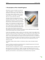
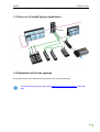
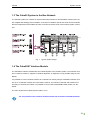
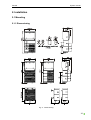
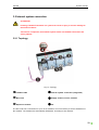
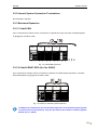
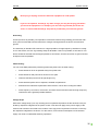
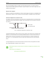
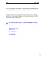
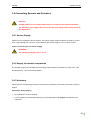
|Manual
Cube20 System
| Description
| Installation
| Configuration Notes
| Diagnostics
Cube20
System manual
Publisher's Note
Instruction manual for devices from the Cube20 product line
General System Manual
Version 1.3
Edition 07_11 EN
Article number 56030
Murrelektronik GmbH
Falkenstraße 3
D-71570 Oppenweiler
Phone +49 (0) 7191 47-0
Fax
+49 (0) 7191 47-130
[email protected]
2
Cube20
System manual
Service and Support
Website:
www.murrelektronik.com
In addition, our Customer Service Center (CSC) will be glad to assist you:
Our Customer Service Center can support you throughout your project in the planning and conception of customer applications, configuration, installation, and startup. We also offer competent consulting or - in more complex cases - we even provide direct onsite support.
The Customer Service Center provides support tools. It performs measurements for fieldbus systems,
such as ProfiBus DP, DeviceNet, CANopen, and AS interface, as well as energy, heat, and EMC
measurements.
Our coworkers at the Customer Service Center provide their competence, know-how, and years of
experience. They are knowledgeable about hardware and software, and compatibility with products
made by various manufacturers.
You can contact the Customer Service Center at
telephone number +49 (0) 7191 47-424
or by email at [email protected].
3
Cube20
System manual
About the User Manual and its Structure
4
Cube20
System manual
Here are links to the bus unser manuals:
>>> PROFIBUS (www.profibus.com)
>>> PROFINET (www.PROFINET.com)
>>> ODVA (www.odva.org)
5
Cube20
System manual
Table of Contents
Publisher's Note ....................................................................................................................................... 2
Service and Support ................................................................................................................................ 3
About the User Manual and its Structure ................................................................................................. 4
Table of Contents..................................................................................................................................... 6
Important Information ............................................................................................................................... 9
1. Description of the Cube20 System .................................................................................................... 11
1.1 Picture of a Cube20 System Application ...................................................................................... 12
1.2 Explanation of the bus systems ................................................................................................... 12
1.3 The Cube20 System in the Bus Network ..................................................................................... 13
1.4 The Cube20/67 Interface Module................................................................................................. 13
2. Installation .......................................................................................................................................... 14
2.1 Mounting ....................................................................................................................................... 14
2.1.1 Dimensioning ......................................................................................................................... 14
2.1.2 Spacing .................................................................................................................................. 15
2.1.3 Mounting position .................................................................................................................. 15
2.1.4 Mounting Cube20 Modules on DIN rail and mounting the terminals ..................................... 16
2.1.5 Mounting the Potential Terminal Block on DIN rail and on the Cube20 Module ................... 17
2.1.6 Labeling of Terminals ............................................................................................................ 18
2.1.7 Terminal Wiring ..................................................................................................................... 19
2.2 Connection Diagram .................................................................................................................... 19
3. Configuration Notes ........................................................................................................................... 19
3.1 System Components .................................................................................................................... 20
3.1.1 Product Designation Code..................................................................................................... 20
3.1.2 Bus node................................................................................................................................ 21
3.1.3 I/O modules ........................................................................................................................... 22
3.1.4 Cube20/67 Interface, Art. No. 56140 ..................................................................................... 22
3.1.4.1 Topology ......................................................................................................................... 23
3.1.5 Accessories ........................................................................................................................... 24
6
Cube20
System manual
3.1.5.1 Potential terminal block ................................................................................................... 24
3.1.5.2 Label sheet ..................................................................................................................... 25
3.1.5.3 Coding pieces for terminals ............................................................................................ 25
3.1.5.4 Profibus connector .......................................................................................................... 25
3.1.5.5 BUS cable ....................................................................................................................... 25
3.1.5.6 Cable for Cube67 connection ......................................................................................... 26
3.1.5.7 Cable for Cube67 connection ......................................................................................... 26
3.1.5.8 MICO ............................................................................................................................... 27
3.2 Internal system connection .......................................................................................................... 28
3.2.1 Topology ................................................................................................................................ 28
3.2.2 Internal System Connection Terminations ............................................................................ 29
3.2.3 Maximum Expansion ............................................................................................................. 29
3.2.3.1 Cube20 BN ..................................................................................................................... 29
3.2.3.2 Cube20 BN67 DIO8 (Art. No. 56450) ............................................................................. 29
3.2.3.3 Cube20/67 Interface Module (Art. No. 56140) ................................................................ 30
3.2.4 Load rating ............................................................................................................................. 30
3.3 Power Supply ............................................................................................................................... 31
3.3.1 Configuration Notes ............................................................................................................... 31
3.3.2 Galvanic separation ............................................................................................................... 32
3.3.2.1 Information on the analog I/O modules........................................................................... 32
3.3.2.2 Information on the Cube20/67 interface module (Art. Nr. 56140) .................................. 32
3.3.3 Recommended power supply units ....................................................................................... 33
3.3.4 Cable Cross Sections ............................................................................................................ 34
3.3.5 Electromagnetic Compatibility (EMC) .................................................................................... 34
3.4 Connecting Sensors and Actuators.............................................................................................. 38
3.4.1 Sensor Supply ....................................................................................................................... 38
3.4.2 Supply of external components ............................................................................................. 38
3.4.3 Actuators................................................................................................................................ 38
3.5 Information about the data of the I/O modules ............................................................................. 40
4. Diagnostics ........................................................................................................................................ 41
7
Cube20
System manual
4.1 LED - Indicators............................................................................................................................ 41
4.1.1 Significance of the states of the "Power" LED....................................................................... 41
4.1.1.1 On the bus node ............................................................................................................. 41
4.1.1.2 Power LED on the I/O modules ...................................................................................... 43
4.1.2 (In the corresponding product manual!) Meaning of the "Bus Run" LED and the "Cfg F" LED
states .............................................................................................................................................. 44
4.1.3 Displays for Supply Voltage at the Terminals of All Modules ................................................ 44
4.1.3.1 Module Supply ................................................................................................................ 44
4.1.3.2 Periphery Supply............................................................................................................. 45
4.1.4 Signal Logic State and LED Behavior ................................................................................... 46
4.1.4.1 Digital modules ............................................................................................................... 46
4.1.4.2 Analog Modules .............................................................................................................. 47
4.1.4.3 Cube20/67 Interface Module, Art. No. 56140 ................................................................. 49
4.2 (In the corresponding product manual!) Diagnostics via the Fieldbus ......................................... 49
Glossary ................................................................................................................................................. 50
Legal Provisions ..................................................................................................................................... 53
8
Cube20
System manual
Important Information
Necessary basic knowledge
This manual contains general system information. For more detailed information please refer to the
corresponding bus manuals and to the product manuals.
Understanding this manual requires general knowledge in automation technology.
Symbols and Icons
This manual contains information and instructions you must comply with in order to maintain safety
and avoid personal injury or damage to property. They are identified as follows:
Notes indicate important information.
Warnings contain information that, if you ignore this information, may cause damage
to equipment or other assets or, if you fail to comply with safety precautions, may
constitute a danger to the user's health and life.
These instructions are recommendations issued by Murrelektronik.
Intended Purpose
Read this manual carefully before startup of the equipment. Keep it in a location that is accessible to
all users at all times.
The products that are described in this manual were developed, manufactured, tested, and documented in compliance with the relevant safety standards. In normal cases, these products do not constitute any danger to persons or objects, provided the handling specifications and safety instructions
described in this manual are observed. They meet the following requirements:
•
EMC directive (2004/108/EEC)
9
Cube20
System manual
The products are designed for industrial use. An industrial environment is defined as one in which
loads are not connected directly to the public low-voltage power grid. Additional measures must be
taken if the products are used in private, business, or trade environments.
The safe, troublefree functioning of the products requires proper transportation, storage, mounting,
and installation, and careful operation. Operation of the devices for their intended purposes is only
guaranteed when the enclosures are fully mounted. If aggressive media are used, check their material
resistance depending on the application.
Current safety and accident prevention laws valid for a specific application must be observed for the
configuration, installation, setup, maintenance, and testing of the devices. The power supply must
correspond to SELV or PELV standards. Power sources in accordance with EN 61558-2-6 (transformer) or EN 60950-1 (switched-mode power supply) meet these requirements.
Only use cables that meet the requirements and regulations for safety, electromagnetic compatibility,
and, if necessary, telecommunications terminal equipment specifications.
Information on the cables and accessories that are suitable for use with this product
are contained in the section "System Components" of this manual.
Qualified Personnel
Only qualified, trained electricians knowledgeable in the safety standards of automation systems may
configure, install, set up, maintain, and test the devices. The requirements concerning qualified personnel are dependent on the requirements profiles described in ZVEI and VDMA. For this reason,
electricians must know the contents of the manual "Weiterbildung in der Automatisierung" (Further
Training in Automation Systems) published by ZVEI and VDMA published by Maschinenbau-Verlag,
Post Box 710864, 60498 Frankfurt, Germany) before installing and maintaining the devices. These are
specialists who are capable of assessing the work to be done and the possible dangers on account of
their technical training, knowledge, experience, and knowledge of the relevant standards; or who have
an identical level of knowledge equivalent to technical training since they have worked in the same
area for many years.
Only Murrelektronik technical personnel are allowed to execute work on the hardware and software of
our devices, if they are devices not described in this manual.
Unqualified tampering with the hardware or software, or failure to observe the warnings cited in this manual may result in severe personal injury or damage to property.
10
Cube20
System manual
1. Description of the Cube20 System
Murrelektronik Cube20 is a fieldbus I/O station with
modular expandability. It is strictly oriented by the requirements of modern wiring in control cabinets. Due
to its compact design Cube20 provides a very high
channel density in a small space. This allows up to
488 I/Os on just 90 centimeters of DIN rail.
All Cube20 modules are equipped with coded plug
terminals for typical control cabinet 1-wire connectivity.
Murrelektronik’s experience in electrical engineering
shows that many control cabinets have up to 100 I/O
points or more. Compared to the complex structure of
I/O stations consisting of numerous individual components, Cube20 offers the advantage of lower installation costs and smaller profiles and its modular design
does not leave many terminals unused. Moreover,
using Cube20 has an impact on inventory and purchasing. It helps to significantly reduce the hidden
costs caused by handling various individual components.
Thanks to the expandability of Cube20, customers can choose from a variety of many digital and analog input and output models with universal applications. There are different bus nodes available for the
connection to a higher-level system, therefore it is possible to exchange buses without changing the
system. This is a great advantage for the designer: Customer-specific requirements can be realized in
a simple and time-saving way. Cube20 can be operated as stand-alone unit at the fieldbus, and also in
combination with Cube67. This allows an even more economic use of existing resources such as
Cube67 bus nodes.
It is possible to operate Cube67 modules on a Cube20 bus node by using a Cube20/67 interface
module.
Cube20 I/O modules are galvanically separated and have an integrated supply terminal. This simplifies the implementation of different potential groups.
All Cube20 modules are equipped with a continuous, convenient diagnostic system as standard. LEDs
light up precisely where the problem is; in addition a message is generated and sent to the control.
This simplifies the first startup and allows pinpoint localization of sources of interference. This helps to
significantly reduce downtime, increase productivity, and troubleshoot faulty components.
11
Cube20
System manual
1.1 Picture of a Cube20 System Application
1.2 Explanation of the bus systems
For the descriptions of the different bus types please refer to the bus manuals.
You will find an overview in the section "Manual Overview and Layout" in this manual.
12
Cube20
System manual
1.3 The Cube20 System in the Bus Network
The Cube20 system is a modular I/O system with IP20 protection for decentralized collection and control of digital and analog process variables. It consists of a fieldbus specific bus node and I/O modules
that are independent of the fieldbus and are connected to the bus node via an internal system connection.
Fig. 1: Typical System Design
1.4 The Cube20/67 Interface Module
The Cube20/67 interface module links the Cube20 System to the Cube67 System. The interface module is a passive module. It supplies no fieldbus diagnostic. A diagnostic is only possible using an LED
display.
It is possible to connect Cube67 modules to a Cube20 bus node by using a Cube20/67 interface module. Up to 15 Cube67 modules are connectable. However, the number of Cube20 and Cube67 modules may not exceed 15 modules. It is possible to connect the Cube20 BN67 DIO8 module, Art. No.
56450.
The max. length of the Cube67 system cable is 10 m.
The 0 V potential of the interface module must be tied to the bus node GND potential.
13
Cube20
System manual
2. Installation
2.1 Mounting
2.1.1 Dimensioning
Fig. 2: Dimensioning
14
Cube20
System manual
2.1.2 Spacing
Fig. 3: Spacing
2.1.3 Mounting position
Fig. 4: Mounting position
The potential terminal boxes can be mounted in any position.
15
Cube20
System manual
REMOVE TERMINALS
WIRING
SNAP ON
2.1.4 Mounting Cube20 Modules on DIN rail and mounting the terminals
Fig. 5: Mounting Cube20 Modules on DIN rail and mounting the terminals
16
Cube20
System manual
2.1.5 Mounting the Potential Terminal Block on DIN rail and on the
CONNECT TO CUBE20 MODULES
SNAP ON
Cube20 Module
Fig. 6: Mounting the Potential Terminal Block on DIN rail and on the Cube20 Module
17
Cube20
System manual
2.1.6 Labeling of Terminals
The figures X0 to X3 indicate the up to 4 terminal rows, the top row always beginning with X0.
terminal rows
module supply
analog channels
digital channels
periphery supply
Fig. 7: Labeling of the terminals
Below a short explanation of the terms:
Module Supply
•
"UI" Supply voltage of internal supply.
•
"UA" (red): Actuator supply.
•
"GND": Module - Ground
Periphery Supply
•
"US": Sensor supply.
•
"UA0…UA3" (brown): Actuator supply.
•
„0V“: 0 Volt Potential
•
: Function ground
Digital modules
•
Inputs and outputs are labeled „00…03“ or „00…07“. Furthermore, the labeling corresponds to
channel number and bit position.
Analog Modules
•
Inputs and outputs are labeled „S0…S3", „U0…U3 and I0…I3", „+R0…+R3", „TH0+…TH3+" or
also „KTY0…KTY1“. Furthermore, the labeling corresponds to channel number and bit position.
18
Cube20
System manual
2.1.7 Terminal Wiring
Fig. 8: Terminal Wiring
2.2 Connection Diagram
For the exact connection diagram and settings please refer to the corresponding
product manuals.
You will find an overview in the section "Manual Overview and Layout" in this manual.
3. Configuration Notes
This chapter contains a short description of the Cube20 system components and information that is
important during the electromechanical planning phase.
19
Cube20
System manual
3.1 System Components
3.1.1 Product Designation Code
The designation format of Cube20 system components explains their function.
Examples:
Name
CUBE20
Description
BN-P
DIO8
I/O Channels
A
D
= Analog
= Digital
I
O
= Input
= Output
Fieldbus system
BN
= Bus node
67
P
E/IP
PNIO
= Cube67
= ProfiBus
= EtherNet/IP
= ProfiNet
Product family
Fig. 9: Example Designation Code
Name
CUBE20
Description
DI32
I/O Channels
A
D
= Analog
= Digital
I
O
= Input
= Output
(a special function as
e.g.: Interface Cube20/67
is also possible here)
Product family
Fig. 10: Example Designation Code
20
Cube20
System manual
3.1.2 Bus node
The purpose of the Cube20 System is the decentralized routing of signals at the I/O level and the
supply of this information over a fieldbus network (e.g. Profibus). The central unit is the bus node that
connects the Cube20 I/O modules to the fieldbus.
The bus node is supplied via the "UB" terminal; the BN67 is directly supplied via the internal system
connection of Cube67.
The bus node has a connection for the internal system connection that connects a maximum of 15 I/O
modules or 3 I/O modules ("BN67"). The parts are linked together by plugging in the ribbon cable.
Article number
Description
56001
Cube20 BN-P DI8
56005
Cube20 BN-E/IP DI8
56006
Cube20 BN-PNIO DI8
56450
Cube20 BN67 DIO8
Tab. 1: Bus node
For the exact connection diagram and settings please refer to the corresponding
product manuals.
Exception:
"Cube20 BN67 DIO8 Art. No. 56450" which can be found as Cube67 connection in the
Cube67 manuals.
„Cube20/67-Interface Art. No. 56140“ which can be found as Cube20/67-Interface in
the Cube20 product manual.
You will find an overview in the section "Manual Overview and Layout" in this manual.
21
Cube20
System manual
3.1.3 I/O modules
These modules are connected to the bus node via the internal system connection.
Extension modules
Extension modules are fitted out with an extension interface for the internal system connection, i.e. the
latter can be routed to the following I/O modules. Up to four I/O modules can be connected to one
segment. Attention! Only 3 I/O modules can be connected to the Cube20 BN67 DIO8, Art.No. 56450,
(our Cube67 > Cube20 interface). An extension module can also be the sole or the last module of a
segment.
Article number
Description
56112
Cube20 DI32
56117
Cube20 DO16 (2A)
56118
Cube20 DO32
56121
Cube20 DI32 NPN / PNP
56168
Cube20 DI16DO16
56200
Cube20 AI4 U/I
56201
Cube20 AI4 U/I
56220
Cube20 AO4 U/I
56221
Cube20 AO4 U/I
56230
Cube20 AI4 RTD
56240
Cube20 AI4 TH
Tab. 2: Extension modules
3.1.4 Cube20/67 Interface, Art. No. 56140
The Cube20/67 interface module is a module that links the Cube20 System to the Cube67 System.
The Cube20/67 interface module is not an active module. It is not parameterized and supplies no diagnostics. The module is fieldbus-independent but must always be linked to the bus node (BN) via the
internal system connection. The power LED indicates the status of the internal Cube20 system link.
The US and UA LEDs indicate the Cube67 status. Galvanically, UA and UI are at the same potential
(0V). To avoid EMC-related impacts, the bus mode GND must be linked to the bus node 0V of the
Cube20/67 interface module.
22
Cube20
System manual
Article Number
Description
56140
Cube20/Cube67 Interface
3.1.4.1 Topology
Fig. 11: Example of a Cube20/67 interface module with 2 system topology variants
Example
VARIANT 1: Cube20 + Cube67
VARIANT 2: Cube20 + Cube20
1 Cube20 bus node
+
4 Cube20 modules
+
1 Cube20/67 interface module
+
4 Cube67 modules
=
10 modules
1 Cube20 bus node
+
4 Cube20 modules
+
1 Cube20/67 interface module
+
1 Cube20 BN67 DIO8 M12
+
2 Cube20 modules
=
9 modules
Max. length of Cube67 system cables
10 m
23
Cube20
System manual
Note on system topology with a Cube20/67 interface module:
•
A modular Cube20/67 fieldbus station can comprise up to 16 modules (Cube20 bus node + 15
Cube20/67 modules).
•
The Cube20/67 interface module is counted as a module and can be included in the configuration (but need not).
•
The Cube20/67 interface module can only be operated on Cube20 bus nodes and may only
be used once in the station setup.
•
Only max. 3 Cube20 modules can be connected to the Cube20 BN67 DIO8 M12 Art. No.
56450.
It is permitted to utilize the Cube20 BN67 DIO8 M12 Art. No. 56450 to connect to the
Cube20/67 interface module Art. No. 56140.
3.1.5 Accessories
3.1.5.1 Potential terminal block
Article number
Description
56078
Potential terminal block gray / gray / brown / blue
56079
Potential terminal block gray / gray / yellow / blue
56080
Potential terminal block yellow / blue / yellow / blue
56081
Potential terminal block brown / blue / brown / blue
56082
Potential terminal block green / black / black / black / black
56109
Potential terminal block brown / brown / blue / blue
56110
Potential terminal block blue / blue / yellow / yellow
56111
Potential terminal block blue / yellow / brown / blue
Tab. 3: Potential terminal block accessories
24
Cube20
System manual
3.1.5.2 Label sheet
Article number
Description
56113
Label sheet
Tab. 4: Label sheet accessories
3.1.5.3 Coding pieces for terminals
Article number
Description
56115
Coding pieces for terminals
Tab. 5: Accessories for terminal coding pieces
3.1.5.4 Profibus connector
Article number
Description
55585
Profibus plug with insulation displacement for rigid cables
55586
Profibus plug with insulation displacement for rigid cables and with programming connection
55587
Profibus plug with insulation displacement for flexible cables
55588
Profibus plug with insulation displacement for flexible cables and with programming connection
Tab. 6: AccessoriesProfibus plug
3.1.5.5 BUS cable
Article number
Description
7000-00000-8409999
Bus cable for Profibus, 100 m bundle
7000-00000-7989999
Bus cable for ProfiNet CAT5, 100 m bundle
7000-00000-7989999
Bus cable for ProfiNet CAT5, 100 m bundle
Tab. 7: BUS cable
Most cables and connectors are available in angled style.
25
Cube20
System manual
3.1.5.6 Cable for Cube67 connection
Cube67 system connection
Article number
Description
7000-46041-8020015
Male - straight /
Female - straight
green
Cable length
0.15 m
7000-46041-8020030
0.3 m
7000-46041-8020060
0.6 m
7000-46041-8020100
1m
7000-46041-8020150
1.5 m
7000-46041-8020200
2m
Tab. 8: Cube67 system connection
3.1.5.7 Cable for Cube67 connection
Cube67 system connection
Article number
7000-15001-4140150
Description
Male - straight
with open ended wires
gray
Cable length
1.5 m
7000-15001-4140300
3m
7000-15001-4140500
5m
7000-15001-4140750
7.5 m
7000-15001-4141000
10 m
Tab. 9: Cube67 system connection
We offer a wide product range of actuators / sensors. Connectors, cables, and adapters up to customized parts.
26
Cube20
System manual
3.1.5.8 MICO
Article number
Description
Nominal operating branch-circuit current (full load)
9000-41034-0100400
MICO 4.4 (4 channels)
4 A each
9000-41034-0100600
MICO 4.6 (4 channels)
6 A each
9000-41034-0401000
MICO 4.10 (4 channels)
10 A each
9000-41042-0100400
MICO 2.4 (2 channels)
4 A each
9000-41042-0100600
MICO 2.6 (2 channels)
6 A each
9000-41042-0401000
MICO 2.10 (2 channels)
10 A each
Tab. 10: Overview MICO variants
Information on products and accessories is available in our catalog and our online
shop at: onlineshop.murrelektronik.com
27
Cube20
System manual
3.2 Internal system connection
ATTENTION:
Inverting Cube20 I/O modules in a system can result in injury or serious damage to
man and/or material.
Therefore it is important, that Cube67 system cables and Cube67 I/O modules are
clearly labeled.
3.2.1 Topology
Fig. 12: Topology
nFieldbus cable
q Internal system connection (integrated)
o Bus node
r Supply: module, sensor, actuator
p Expansion module
s I/O
The bus node has a connection for up to 15 I/O modules. It is not necessary to set the addresses of
the modules. The modules are automatically addressed, according to their position.
28
Cube20
System manual
3.2.2 Internal System Connection Terminations
No terminations required.
3.2.3 Maximum Expansion
3.2.3.1 Cube20 BN
Up to 15 expansion modules can be connected to a Cube20 bus node. The parts are linked together
by plugging in the ribbon cable.
Fig. 13: Cube20 BN expansion
3.2.3.2 Cube20 BN67 DIO8 (Art. No. 56450)
Up to 3 expansion modules can be connected to a Cube67 to Cube20 system expansion. The parts
are linked together by plugging in the ribbon cable.
Fig. 14: Cube67 to Cube20 system expansion
In addition the requirements for the maximum expansion of the Cube67 system (system
connection) have to be observed. They are described in the Cube67 or Cube67+ System
Manual (art. no. 56970).
29
Cube20
System manual
3.2.3.3 Cube20/67 Interface Module (Art. No. 56140)
Up to 15 modules can be connected to a Cube20 system expansion. The CUBE67 system cable is
used as the electrical connection. Sensor and actuator power supply for the Cube67 modules is provided via the Cube20/67 interface.
Refer to the requirements for maximum expansion of the Cube67 System
(system link). You will find this in Cube67 or Cube67+ System Manual (Art. No.
56970).
Note the sequence:
It is not permitted to connect the Cube20/67 interface module Art. No. 56140 downstream of a Cube20 BN67 DIO8 Module Art. No. 56450.
The max. length of the Cube67 system cable is 10 m.
3.2.4 Load rating
It is not necessary to pay attention to the load of the internal system connection, because the I/O
supply is connected directly to the corresponding I/O module.
30
Cube20
System manual
3.3 Power Supply
3.3.1 Configuration Notes
Bus modules require a direct-voltage power supply of typically 24 VDC (SELV/PELV) which must
comply with the regulations of conventional industrial power-utility companies.
In order to optimize interference immunity, we advise you to power sensors, bus, and
actuators from different sources. The power supply should be primary switchedmode or regulated power supplies.
The output of the power supply units depends on the number of connected load and their output.
In any case, it must be ensured that the system voltage does not drop below 18 V DC
viewed from the system power supplies and measured at the remotest slave. System
response becomes unspecific if sensor and bus power supply drop below 18 V DC.
Primary switched-mode power supply units normally permit an increase in output
voltage to the amount of the rated voltage in order to compensate for any power
losses.
Modules with digital inputs support the direct connection of commercially available sensors. A separate power supply may be necessary for the sensors if the total power required is high due to the
number of slaves or a high power draw of the sensors.
31
Cube20
System manual
3.3.2 Galvanic separation
Galvanic separation between the supply of the system supply and the sensor supply has to be provided. In order to maximize the electromagnetic compatibility we recommend to ensure galvanic separation.
Fig. 15: Typical system structure with galvanic separation
The illustration above shows a typical Cube20 system structure with digital inputs and outputs (DI/DO)
and analog inputs and outputs (AI/AO).
Furthermore it shows that Profibus, I/O area and I/O supply as well as the supply of the system electronics are galvanically separated. The internal electronics of the digital input/output modules are supplied by the system cable. The internal electronics of the analog input/output modules are supplied via
the input/output supply voltage.
3.3.2.1 Information on the analog I/O modules.
The I/O supply voltage must always be connected, otherwise communication via the internal system
connection is interrupted starting from the analog module that is not supplied.
3.3.2.2 Information on the Cube20/67 interface module (Art. Nr. 56140)
Galvanically, the supply voltages UA and UI are at the same potential (0V).
Galvanically, connected Cube67 modules are not separated from the module electronics of the
Cube20 System.
32
Cube20
System manual
3.3.3 Recommended power supply units
Primary switched-mode power supply units from Murrelektronik are specially designed to power automation systems. For this reason, we recommend them to power the modules.
Note for DeviceNet users:
We recommend so-called Class 2 power supplies for the supply of the DeviceNet bus.
Please contact our sales support regarding information about "ODVA" certified power supplies.
Phases
Output rating
Input voltage
95...132 V AC
Input voltage
185...265 V AC
1
240 W / 10 A
85086
85085
1
480 W / 20 A
85088
85087
Tab. 11: Recommended power supply units MCS Power+ single phase
Phases
Output rating
Input voltage
3 x 340...460 V AC
3
240 W / 10 A
85095
3
480 W / 20 A
85097
3
960 W / 40 A
85099
Tab. 12: Recommended power supply units MCS Power+ three phase
Murrelektronik offers an extensive range of primary switched power supply units.
Please refer to our catalogs or:
www.murrelektronik.com
33
Cube20
System manual
3.3.4 Cable Cross Sections
Fig. 16: Cable cross sections
3.3.5 Electromagnetic Compatibility (EMC)
This device meets the requirements of EC Directive 89/336/EEC "Electromagnetic
Compatibility".
This device is Class A equipment and may cause radio-frequency interference in residential areas. In this case, the operator may be required to implement adequate
countermeasures.
The devices described in this manual each meet the relevant standards for electromagnetic compatibility. However, this does not mean that their electromagnetic compatibility is still guaranteed when
installed in a plant or machine.
For this reason, we urgently advise you to comply with the instructions on installation in accordance
with EMC requirements below. Only then can you assume that the overall system complies with EMC
requirements, provided CE-marked components are used exclusively.
Protection against Electrostatic Discharge
The products described in this manual contain complex semiconductor components which may be
destroyed or damaged by electrostatic discharge (ESD).
Damage does not necessarily lead to immediate, detectable failure, or malfunction. These states may
be even delayed, or occur sporadically.
The generally accepted safety precautions for ESD sensitive devices must be observed when handling the devices. The following precautions must be taken:
34
Cube20
System manual
Never plug or unplug connectors while the equipment is under power.
If you are an operator, discharge any static charge you may be carrying just before
you touch the equipment. For example, you can touch a grounded part of the machine, or wear an ESD discharge strap that is permanently connected to ground.
Grounding
A short (as short as possible), low-impedance connection between the grounding point and the reference ground is essential to divert interference voltages running between the device and reference
ground.
The inductivity of standard FE conductors is a high impedance for high-frequency interference voltages. For this reason, the use of grounding straps is advisable. If this is not possible, a fine-wire FE conductor should be selected with the largest possible cross section, and the connection to ground should
be kept as short as possible.
Cable Routing
You can avoid EMC problems by observing elementary basic rules of cable routing:
•
Route data lines as far as possible away from power lines.
•
Route data lines and power lines at least 10 cm apart.
•
Intersect data and power lines at right angles only.
•
Route data and power lines in separate, shielded compartments.
•
Remember the interference potential of other devices or lines when routing the cables.
•
Place frequency converters, motor lines, and other devices and lines that emit high-frequency
interference at the greatest possible distance.
Voltage Drops
Short-term voltage drops (<10 ms) normally pose no operational problems as the electronics are protected by capacitors integrated in the power circuits. This does not apply to the power supply of the
sensors and actuators connected to the module. Their high power requirement cannot be covered by
the capacitors integrated in the device. For this reason, even transient interruptions of the actuator
supply can result in undesirable switching operations.
35
Cube20
System manual
Due to the integrated input filter, a change in the input signal of less than 1 ms does not cause a
change of the input state signaled to the Master. Longer interruptions of the sensor supply may cause
changes of the input signal.
Separate Power Supplies
Sensors or actuators can be powered by a common power supply unit. However, it is preferable to use
separate power supplies in order to maximize the electromagnetic compatibility of the overall system.
Interference Suppression of Inductive Loads
The outputs of the devices described in this manual have an integrated protective circuit that provides
safety against high-energy interference voltages, such as those that occur when inductive consumers
are switched.
Inductive load
(e.g. solenoid valves)
Varistor or bipolar suppressor diode
Fig. 17: Interference Suppression of Inductive Loads
A suppressor diode helps to quickly reduce the energy stored in the inductive load of a magnetic field.
However, it is recommended to use commercially available protection circuits for inductive loads, especially loads in the range of the maximum current-carrying capacity of a channel at switching frequencies of > 1 Hz. These protection circuits can reduce the energy stored in the connected inductances.
The high voltages that occur when inductive loads are shut down result in strong fields in the cables
with consequential faults in adjacent circuits or devices.
Murrelektronik offers a wide selection of interference suppression products for this
purpose.
Please refer to our catalogs or:
onlineshop.murrelektronik.com
36
Cube20
System manual
Other Measures and Limits
In some system configurations, the requirements for interference emission and immunity from interference can only be met with additional measures, or even not at all. In these cases, the EMC within the
system is also dependent on the single components of other manufacturers.
Mains filters are a suitable means of reducing line-conducted interference. Various manufacturers
offer optical-fiber converters. This data transmission technology is basically immune to EMC interferences. However, this does not apply to the electronic conversion circuits. For this reason, the use of
optical fibers does not solve all EMC problems.
Our certified test center will answer your questions regarding EMC. They will give
advice on guaranteeing compliance with the EMC directive for the system you produce.
Murrelektronik Test Center,
Grabenstraße 27,
D-71570 Oppenweiler
Phone ++7191 47-334,
Fax ++7191 47-323,
[email protected]
37
Cube20
System manual
3.4 Connecting Sensors and Actuators
Attention:
Cube20 modules are no safety-related devices according to the relevant standards.
The Off-status of the outputs must not be used to meet safety-related requirements of
the application!
3.4.1 Sensor Supply
Sensors can be supplied by the I/O module. The sensor supply of each module is secured by an electronic, self-resetting fuse. The max. current draw for the sensor supply is 0.7 A for each module.
There is no derating for the sensor supply.
WARNING!
The capacity per digital input is 10 nF.
3.4.2 Supply of external components
The actuator supply (not switchable) for the analog output modules is provided. For each UA0...UA3
terminal (brown), 1.6 A current are available.
3.4.3 Actuators
Please see the corresponding Instruction manual for the maximum current that can be taken from the
outputs.
Information about derating:
•
AO modules do not have derating.
•
For DO modules, the following derating curves are applicable, if all outputs are switched at the
same time.
38
Cube20
System manual
Derating DO for 0.5 A
Fig. 18: Derating curve of the DO modules for 0,5A
Derating DO for 2 A
Fig. 19: Derating curve of the DO modules for 2A
ATTENTION:
The module may be damaged if the actuator power supply polarity is reversed.
To increase power, outputs may be connected in parallel.
If an overload or short-circuit occurs at an output, that output is shut down. This output will remain disabled even when the error has been corrected. In order to reset the
short-circuit memory, the output must be reset or the actuator supply switched off.
39
Cube20
System manual
3.5 Information about the data of the I/O modules
By means of the device identification the fieldbus master gets information about the data capacity,
operation mode, etc. for peripheral modules (I/O modules). After having detected the slaves the master generates from this data a map of all detected I/O modules of the bus system. The data of the I/O
modules are mapped in a list according to the logical arrangement in the fieldbus.
The user can now map the entries of the bus master list to addresses in the PLC. This will create the
process image of the inputs and outputs (PII/PIO).
PLC
Fieldbus
I/O Modules
Fieldbus Master
Periphery Image „Inputs“
Process Image
Inputs
(PII)
Master Node 1
Input Data Node 1
Diagnosis Data Node 1
• Input Data
• Diagnosis
• Output Data
Input Data Node 2
Diagnosis Data Node 2
Input Data Node 3
Diagnosis Data Node 3
Bus
SPS program
Master Node 2
• Input Data
• Diagnosis
• Output Data
Periphery Image “Outputs”
Output Data Node 1
Output Data Node 2
Output Data Node 3
Bus
Process Image
Outputs
(PIO)
Master Node 3
• Input Data
• Diagnosis
• Output Data
Fig. 20: Data transfer between PLC, fieldbus master and bus devices
Data transfer between PLC, fieldbus master and bus devices
For the module specific I/O data, please refer to the corresponding product manuals.
You will find an overview in the section "Manual Overview and Layout" in this manual.
40
Cube20
System manual
4. Diagnostics
4.1 LED - Indicators
4.1.1 Significance of the states of the "Power" LED
4.1.1.1 On the bus node
The "Power" LED indicates the status of the Cube20 system voltage and the internal
communication.
Fig. 21: Example Power LED on Cube20 Modules
41
Cube20
System manual
Behavior of the Power Led of Cube20 BN Modules
Color
Significance for Power LED
green
System voltage (>12V) available
Green
flashing
System connection in the
Cube20 system is interrupted,
no. of flashing pulses corresponds to the position of the
faulty expansion module
(1…15), with several modules
the closest one
Remedy
Replacement of the affected module and
power reset at terminal UB of the Cube20
BN module
Example:
off
No system power (<12V)
Increase voltage
Tab. 13: Behavior of the Power Led of Cube20 BN Modules
42
Cube20
System manual
4.1.1.2 Power LED on the I/O modules
The "Power" LED indicates the status of the Cube20 system voltage and the internal
communication.
Fig. 22: Example Power LED on Cube20 Modules
Behavior of the Power LED of Cube20 I/O modules
Color
Significance for Power LED
fast flashing
(approx.
20Hz)
System power available and
module exchanging data
off
No system power via the
Cube20 system connection
Remedy
•
Wait for initialization of the Cube20
system (can take some seconds)
•
Check the internal system connection
(ribbon cable) and power reset at terminal UB of the Cube20 BN module
Tab. 14: Behavior of the Power LED of Cube20 I/O modules
43
Cube20
System manual
Verhalten der Power-LED an Cube20/67-Interface-Modulen
Farbe
Bedeutung für Power LED
Abhilfe
grün
UI und
Weiterschaltung vorhanden
Funktion i.O.
aus
UI fehlt oder
Initialisierung läuft
•
•
UI muss vor dem Starten des Cube20
Systems anliegen.
Initialisierung des Busknotens kann
einige Sekunden in Anspruch nehmen
Tab. 15: Verhalten der Power-LED an Cube20/67-Interface-Modulen
4.1.2 (In the corresponding product manual!) Meaning of the "Bus Run"
LED and the "Cfg F" LED states
They are described in the Cube20 product manuals. For an overview please refer to
the beginning of this manual, chapter "About the User Manual and its Structure".
4.1.3 Displays for Supply Voltage at the Terminals of All Modules
4.1.3.1 Module Supply
There is no LED at terminal "UB". The state of system voltage is signalized by the
Power LED.
See chapter: Significance of the states of the "Power" LED
•
Indicators with „UI“ show the state of the supply voltage for the internal supply.
•
Indicators with „UA“ show the state of the supply voltage for actuators.
44
Cube20
System manual
LED indicator
UI and UA
Response
State
green
Supply voltage OK (>= 18V)
Red
Under voltage (< 18V)
off
Voltage <= 12.5V
Tab. 16: LED Module Supply
4.1.3.2 Periphery Supply
•
Indicators with „US“ show the state of the supply voltage for sensors.
•
Indicators with „UA0…UA3“ show the state of the supply voltage for actuators.
LED Display
US and UA
Response
State
off
Supply voltage OK
Red
Overload or short circuit of the
sensor or actuator supply
Tab. 17: LED Periphery Supply
Two terminals each have one common "US" LED.
45
Cube20
System manual
4.1.4 Signal Logic State and LED Behavior
4.1.4.1 Digital modules
A separate status indicator is assigned for each input and output. It is labeled with "00…03" or
"00…07". Furthermore, the labeling corresponds to channel number and bit position. It is situated
under the corresponding terminal and allows easy mapping to the state of the peripheral components,
sensors and actuators.
Connection of signal logic state and LED behavior at the input
LED Display
Logical value
Voltage
at input
Signal
off
0
0V
NO
input
Yellow
1
24 V
Tab. 18: LED at Input of Digital Modules
Connection of signal logic state and LED behavior at the output
LED Display
Logical value
Voltage
at output
Signal
off
0
0V
Output
Yellow
1
24 V
Red
1
0V
Output in case of
short-circuit
Tab. 19: LED at Output of Digital Modules
When inductive loads are switched off, the diagnostic LED on the output channel of
modules 56118 and 56168 may light up briefly. This does not represent a module malfunction. The module does not sustain any damage.
46
Cube20
System manual
4.1.4.2 Analog Modules
A separate status indicator is assigned for each input and output. The corresponding LED is situated
under the respective terminal.
Cube20 AI4 U/I Art.-No.: 56200 / 56201
The terminals are labeled with the channel numbers "S0…S3".
LED Display
State
Possible diagnostics
off
OK
-
Red
Diagnostics
•
Line break
•
Measuring range overshot
•
Measuring range undershot
Tab. 20: LEDs of the Channels of the Analog Modules Cube20 AI4 U/I Art. No.: 56200 / 56201
Cube20 AO4 U/I Art.-No.: 56220 / 56221
The terminals are labeled with the channel numbers "U0…U3" and "I0…I3".
LED Display
State
Possible diagnostics
off
OK
-
Red
Diagnostics
•
Line break
•
Actuator short circuit
Tab. 21: LEDs of the Channels of the Analog Modules Cube20 AI4 U/I Art. No.: 56200 / 56201
47
Cube20
System manual
Cube20 AI4 RTD Art.-No.: 56230
The terminals are labeled with the channel numbers "+R0…+R3".
LED Display
State
Possible diagnostics
off
OK
-
Red
Diagnostics
•
Line break
•
Measuring range overshot
•
Measuring range undershot
Tab. 22: LED of the channels of the analog module Cube20 AI4 RTD Art.-No.: 56230
Cube20 AI4 RTD Art.-No.: 56240
The terminals are labeled with the channel numbers "TH0+…TH3+".
LED Display
State
Possible diagnostics
off
OK
-
Red
Diagnostics
•
Line break
•
Measuring range overshot
•
Measuring range undershot
•
Wire break cold junction compensation (KTY)
Tab. 23: LEDs of the channels of the analog module Cube20 AI4 TH Art.-No.: 56240
48
Cube20
System manual
4.1.4.3 Cube20/67 Interface Module, Art. No. 56140
Significance of the US / UA Cube67 LED on the M12 socket:
LED Display
Response
green
State
Voltage connected through for Cube67 modules
(up to US > 6V).
red
Short-circuit or overload on Cube67 System.
Same as Cube67 system link.
off
US / UA not available.
Modules not yet initialized.
Tab. 24: US / UA Cube67 LED at M12 socket
4.2 (In the corresponding product manual!) Diagnostics via the
Fieldbus
These diagnostics depend on the fieldbus. Please refer to the corresponding instruction manual of the bus node (BN) used.
For an overview please refer to the beginning of this manual, chapter "About the User
Manual and its Structure".
49
Cube20
System manual
Glossary
Actuator shutdown
"Short circuit or overload at an output causes the output to
switch off."
AI
Analog Input
AO
Analog Output
BN-P
Bus Node - Profibus, bus node - Profibus
Bus-Run-LED
LED that signals the bus status
Bus segment
"Due to the electrical specification of the RS-485 interface, the number of
users
on an RS485 network is limited to 32 users.
If there are more than 32 Profibus users, the network must be
divided into segments by means of repeaters."
Byte
Term from IEC 61158. Corresponds to 1 Byte or 8 bits.
Cfg F-LED
LED to signal a correct/incorrect configuration
DI
Digital input
DIN TH35
DIN standard mounting rail (35x15mm, 35x7.5mm)
DO
Digital Output
DP"
Decentralized periphery. Profibus protocol for rapid cyclical
data exchange."
E/A(I/O)
Input/output -
EC Directive 2004/108/EEC EMC directive
EMC
Electromagnetic Compatibility
ESD
Electrostatic discharge
FE
Function ground
Freeze Command
The input data of the slave are "frozen".
GSD
The Device Master Data describes the technical features of a
Profibus product. This file is required to configure a
Profibus system and is provided by the device manufacturer."
50
Cube20
System manual
I
Current
I/O-
Input/ Output
ID number
"A 16-bit number that identifies a Profibus product uniquely. It
represents a reference for the GSD file. Several devices
have the same ID number, provided they are
described in a common GSD file. This number is awarded by the Profibus user Organization.
IEC 61158
Worldwide standard for Profibus DP and FMS. Successor of
international standard EN 50170, Volume 2."
IP20
Ingress Protection, 20 = Device protection against the ingress of solid
foreign bodies measuring a diameter of more than 12.5 mm (finger protection), the device is not protected against ingress of water with deleterious impacts.
LSB
Least significant bit
LWL
Optical fiber
MSB
Most significant bit.
Ni
Nickel
PAA
Process map of outputs
PAE
Process map of inputs
PELV
Protective Extra Low Voltage
PNO
Profibus User Organization.
Power-LED
LED to signal the operating status
Pt 100
Electrical resistance 100W of a platinum wire at 0°C
+R
High potential sensor connection.
-R
Low potential sensor connection.
Repeater
Coupling element to process signals between Profibus segments.
RL
Sensor power supply in three-wire mode.
RTD
Resistance Temperature Device.
S
Reference potential
SELVSafety Extra Low Voltage.
Simatic Manager
Programming software for program-logic controllers made by Siemens
PLC
Program-logic controller
51
Cube20
System manual
TH
Thermocoupler
TH-
Low potential sensor connection.
TH+
High potential sensor connection
Type E, Type J, Type K,
Type N, Type R
Thermoelements as per DIN EN 60584 standard.
U
Voltage
U/I
Voltage / current
UA (brown terminal)
Actuator power supply
UA (red terminal)
Module power supply
UB
Operating voltage.
UI (red terminal )
Module and sensor supply
US BROWN
sensor supply
VDMA
Verband Deutscher Maschinen- und Anlagenbau e.V. (Association of
German Machinery and Industrial Equipment Manufacturers)
VZ
Sign.
ZVEI
Zentralverband Elektrotechnik- und Elektronikindustrie e.V. (German
Electrical and Electronic Manufacturers' Association).
52
Cube20
System manual
Legal Provisions
Exclusion of Liability
Murrelektronik GmbH has checked the contents of this technical documentation for conformity with the
hardware and software described therein. Changes on an individual case basis cannot be excluded.
For this reason, Murrelektronik gives no warranty for the correctness of the contents and refuses any
liability for errors, in particular for complete conformance. For this reason, Murrelektronik excludes the
warranty for the correctness of its contents and any liability for errors, in particular full conformity.
Should a major contractual obligation be violated by criminal negligence, the liability of Murrelektronik
GmbH shall be limited to damages that typically arise.
Subject to technical changes and alternations in content. We advise that you check at regular intervals
whether this documentation has been updated since corrections that may become necessary due to
technical advances are included by Murrelektronik GmbH at regular intervals. We are gratefully for any
suggestions for improvement.
Copyright
It is prohibited to transfer or photocopy the documentation either in paper or in digital form, reuse or
divulge its contents unless otherwise expressly permitted by Murrelektronik GmbH or in conjunction
with the production of documentation for third-party products that contain products made by Murrelektronik GmbH. Violations will result in liability for damages. All rights reserved, in particular in the event
of the award of patents or granting of utility models.
Right of Use
Murrelektronik GmbH grants its customers a non-exclusive right revocable at any time and for an indefinite period of time to use this documentation to produce their own technical documentation. For this
purpose, the documentation produced by Murrelektronik GmbH may be changed in parts, or
amended, or copied ,and transferred to the customer's users as part of the customer's own technical
documentation on paper or on electronic media. The customer shall then bear sole responsibility for
the correctness of the contents of the technical documentation produced by him.
If the technical documentation is integrated in part, or in full in the customer's technical documentation,
the customer shall refer to the copyright of Murrelektronik GmbH. Furthermore, special attention shall
be paid to compliance with the safety instructions.
Although the customer is obliged to make reference to the copyright of Murrelektronik GmbH, provided
the technical documentation of Murrelektronik GmbH is used, the customer shall market and/or use
the technical documentation on his sole responsibility. The reason is that Murrelektronik GmbH has no
influence on changes or applications of the technical documentation and even minor changes to the
starting product or deviations in the intended applications may render incorrect the specifications contained in the technical documentation. For this reason, the customer is obliged to identify the technical
documentation originating from Murrelektronik GmbH if and inasmuch as the documentation is
changed by the customer. The customer shall be obliged to release Murrelektronik from the damage
claims of third parties if the latter are attributable to any deficits in the documentation. This shall not
apply to damages to the rights of third parties caused by deliberate or criminal intent.
The customer shall be entitled to use the company brands of Murrelektronik GmbH exclusively for his
product advertising, but only inasmuch as the products of Murrelektronik GmbH are integrated in the
products marketed by the customer. The customer shall refer to the brands of Murrelektronik GmbH in
an adequate manner if the brands of Murrelektronik GmbH were used.
53
Murrelektronik GmbH|Falkenstraße 3, D-71570 Oppenweiler|P.O. Box 1165, D-71567 Oppenweiler
Phone +49 7191 47-0|Fax +49 7191 47-130|[email protected]|www.murrelektronik.com
The information in this manual has been compiled with the utmost care. Liability for the correctness, completeness and topicality
of the information is restricted to gross negligence.