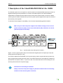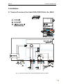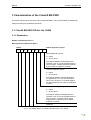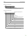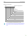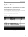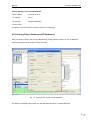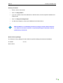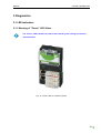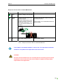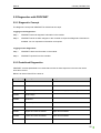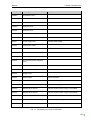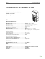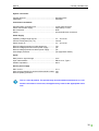
1
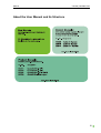
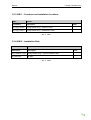
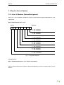
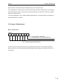
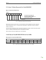
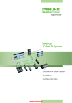
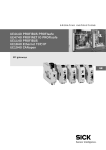
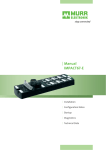
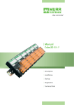
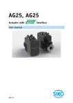
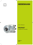
Manual Cube20 ProfiNET Description Installation Characteristics Startup Diagnostics Technical Data Manual Cube20 | BN-PNIO DI8 Publisher's Note Product Manual for Cube20 BN-PNIO DI8 (Article Number: 56006) Version 1.0 Version 07_10 DE Article Number 56006 Murrelektronik GmbH Falkenstraße 3 D-71570 Oppenweiler Fon +49 (0) 71 91 47-0 Fax +49 (0) 71 91 47-130 [email protected] I Manual Cube20 | BN-PNIO DI8 Service and Support Website: www.murrelektronik.com In addition, our Customer Service Center (CSC) will be glad to assist you: The CSC supports customers over the entire course of the project, during planning and the conception of customer applications, configuration, installation, and startup. We also offer competent consulting or – in more complex cases – we even provide direct onsite support. The CSC has a range of support tools. It performs measurements for fieldbus systems, such as PROFIBUS DP, DeviceNet, CANopen, and AS interface, as well as energy, heat, and EMC measurements. Our coworkers at the Customer Service Center provide their competence, know-how, and have years of experience. They are familiar with how products made by various hardware and software manufacturers interact. You can contact the Customer Service Center at telephone number +49 (0) 71 91 47-424 or by email at [email protected]. II Manual Cube20 | BN-PNIO DI8 About the User Manual and its Structure III Manual Cube20 | BN-PNIO DI8 Here are links to the bus user manuals: >>> PROFINET (www.profinet.com) IV Manual Cube20 | BN-PNIO DI8 Table of Contents Publisher's Note ....................................................................................................................................... I Service and Support ................................................................................................................................ II About the User Manual and its Structure ............................................................................................... III Table of Contents .................................................................................................................................... V Important Information ............................................................................................................................ VII 1 Description of the Cube20 BN-PNIO DI8 Art. No. 56006 ..................................................................... 1 2 Installation ............................................................................................................................................ 3 2.1 Terminal Overview of the Cube20 BN- PNIO DI8 Art. No. 56006 ................................................. 3 3 Characteristics of the Cube20 BN-PNIO .............................................................................................. 5 3.1 Cube20 BN-PNIO DI8 Art. No. 56006 ........................................................................................... 5 3.1.1 Parameters .............................................................................................................................. 5 3.2 Identification and Maintenance ...................................................................................................... 8 3.2.1 General Information ................................................................................................................ 8 3.2.2 I&M 0 Module Description ....................................................................................................... 8 3.2.3 I&M 1 – Functions and Installation Locations ......................................................................... 9 3.2.4 I&M 2 – Installation Date ......................................................................................................... 9 3.3 Acyclic Access Options ................................................................................................................ 10 3.3.1 Index 10 Machine Options Management .............................................................................. 10 3.3.2 Index 12 BusControl.............................................................................................................. 11 3.3.3 Index 13 Status Request of the Cube20 BN-PNIO ............................................................... 12 3.4 I/O Data of Cube20 PNIO-DP DI8 Art. No. 56006 ....................................................................... 12 4 Startup of Cube20 BN-PNIO .............................................................................................................. 13 4.1 GSDML File ................................................................................................................................. 13 4.2 Configuration with S7 Hardware Manager................................................................................... 13 4.2.1 General Information .............................................................................................................. 13 4.2.2 Parameterization of Modular Station ..................................................................................... 14 4.2.3 Setting the Topology ............................................................................................................. 14 4.2.4 Identifying Devices in the Network ........................................................................................ 16 V Manual Cube20 | BN-PNIO DI8 4.2.5 Issuing Device Names and IP Addresses ............................................................................. 17 5 Diagnostics ......................................................................................................................................... 19 5.1 LED Indicators ............................................................................................................................. 19 5.1.1 Meaning of "Power" LED States ........................................................................................... 19 5.1.2 Meaning of "Bus Run" LED States ........................................................................................ 21 5.1.3 Meaning of "Cfg F" LED States ............................................................................................. 22 5.1.4 Power Supply Displays at Terminals .................................................................................... 23 5.1.5 Signal-Logic Display and LED Behavior ............................................................................... 24 5.2 Diagnostics with PROFINET........................................................................................................ 25 5.2.1 Diagnostic Concept ............................................................................................................... 25 5.2.2 Predefined Diagnostics ......................................................................................................... 25 5.2.3 Diagnostics of Cube20 BN-PNIO and I/O Modules .............................................................. 27 5.2.4 Diagnostic Message Parameters .......................................................................................... 28 5.3 Troubleshooting ........................................................................................................................... 28 6 Technical Data of 20 BN-PNIO DI8 Art. No. 56006 ........................................................................... 29 7 Accessories ........................................................................................................................................ 31 Glossary .................................................................................................................................................. X Legal Provisions ...................................................................................................................................XIV VI Manual Cube20 | BN-PNIO DI8 Important Information Symbols and Icons This manual contains information and instructions you must comply with in order to maintain safety and avoid personal injury or damage to property. They are identified as follows: Notes indicate important information. Warnings contain information that, if ignored, may cause damage to equipment or other assets or, if you fail to comply with safety precautions, may constitute a danger to the user's health and life. Î Refer to our catalog or visit our inline shop at www.murrelektronik.com. VII Manual Cube20 | BN-PNIO DI8 Intended Purpose Before starting the devices, read this manual carefully. Keep it in a location that is accessible to all users at all times. The products that are described in this manual were developed, manufactured, tested, and documented in compliance with the relevant safety standards. In normal cases, these products do not constitute any danger to persons or objects, provided the handling specifications and safety instructions described in this manual are observed. They meet the specifications of the European EMC Directive (2004/108/EC). DANGER! The devices are not safety devices conforming to the relevant standards. Do not use the OFF state of the outputs to implement safety-related requirements of the system/machine. The products are designed for industrial use. An industrial environment is defined as one in which loads are not connected directly to the public low-voltage power grid. Additional measures must be taken if the products are used in private, business, or trade environments. The safe, troublefree functioning of the products requires proper transportation, storage, mounting, and careful operation. Operation of the devices for their intended purposes is only guaranteed when the enclosures are fully mounted. If aggressive media are used, check their material resistance depending on the application. Current safety and accident prevention laws valid for a specific application must be observed for the configuration, installation, setup, maintenance, and testing of the devices. The power supply must comply with SELV or PELV. Power sources in accordance with EN 61558-2-6 (transformer) or EN 60950-1 (switched-mode power supply) meet these requirements. Only use cables that meet the requirements and regulations for safety, electromagnetic compatibility, and, if necessary, telecommunications terminal equipment specifications. Information on the cables and accessories that are suitable for use with this product are contained in the Appendix to this manual. VIII Manual Cube20 | BN-PNIO DI8 Qualified Personnel Only qualified, trained electricians knowledgeable in the safety standards of automation systems may configure, install, set up, maintain, and test the devices. The requirements concerning qualified personnel are dependent on the requirements profiles described in ZVEI and VDMA. For this reason, electricians must know the contents of the manual "Weiterbildung in der Automatisierung" (Further Training in Automation Systems) issued by ZVEI and VDMA and published by Maschinenbau-Verlag, Post Box 710864, 60498 Frankfurt, Germany) before installing and maintaining the devices. They are therefore electricians who are capable of assessing the work executed and any possible dangers arising from this due to their professional training, knowledge, experience, and their knowledge of the pertinent standards; or who have a level of knowledge equivalent to professional training due to their many years of activity in a comparable field. Only Murrelektronik technical personnel are allowed to execute work on the hardware and software of our devices, if they are devices not described in this manual. WARNING! Unqualified tampering with the hardware or software, or failure to observe the warnings cited in this manual may result in severe personal injury or damage to property. IX Manual Cube20 | BN-PNIO DI8 1 Description of the Cube20 BN-PNIO DI8 Art. No. 56006 The Cube20 System is an I/O system for use IP20 zones for the decentralized capture and control of digital and analog process parameters. It consists of a fieldbus-specific bus node and fieldbusindependent I/O modules that are linked to the bus node via an internal system connection. Please note the galvanic isolation between the input for the system power supply and the input for the sensor and actuator power supplies. To maximize electromagnetic compatibility, we recommend implementing galvanic isolation. Make sure you isolate the power supplies from different voltage sources for the system electronics (UB), sensors (UI), and actuators (UA). Otherwise, we cannot guarantee proper functionality. Galvanic isolation Fig. 1: Typical system setup with galvanic isolation Figure 1 shows a typical system setup of the Cube20 with digital inputs and outputs (DI / DO) and analog inputs and outputs (AI / AO). This section explains that PROFINET, the I/O power supply, and the system electronics power supplies are galvanically isolated from each other. The internal electronics of the digital I/O modules are powered from the system cable, i.e. by the bus node. The internal electronics of the analog I/O modules are powered from the I/O power supply. Information on the analog I/O modules: Always connect the I/O power supply to guarantee communication for all analog modules via the internal system connection. 1 Manual Cube20 | BN-PNIO DI8 Features of the Cube20 BN-PNIO: • Machine Options Management (see 3.3.1) • Status request (see 3.3.3) • Reset by acyclic access (see 3.3) • IM 0 (see 3.3.2) • IM 1 (see 3.2.3) • IM 2 (see 3.2.4) 2 Manual Cube20 | BN-PNIO DI8 2 Installation 2.1 Terminal Overview of the Cube20 BN- PNIO DI8 Art. No. 56006 Fig. 2: Terminal overview of the Cube20 BN-PNIO DI8 Art. No. 56006 3 Manual Cube20 | BN-PNIO DI8 Î For extensions, we recommend our voltage terminal block Art. No. 56109. For more details, please refer to the voltage terminal blocks in the Product Manual. Refer to our catalog or visit our inline shop at www.murrelektronik.com 4 Manual Cube20 | BN-PNIO DI8 3 Characteristics of the Cube20 BN-PNIO The section below lists the functions of the Cube20 BN-PNIO. They can be enabled or disabled by setting/not setting the parameters described. 3.1 Cube20 BN-PNIO DI8 Art. No. 56006 3.1.1 Parameters Number of parameter bytes: 4 Bit assignment of parameter Byte 0 Byte 0 7 6 Global diagnostic reports 5 4 3 2 1 0 Global diagnostic reports 0 = report 1 = do not report This defines whether the diagnostics are reported or not. If you set the parameters to "Do not report", no diagnostics are reported by bus nodes or expansion modules. Channel diagnostic reports 0 = report 1 = do not report This defines whether channel diagnostics are reported or not. If you set the parameters to "Do not report", no channel diagnostics are reported by bus nodes or expansion modules. Sensor power supply diagnostic reports 0 = report 1 = do not report This defines whether the diagnostics are reported or not. If you set the parameters to "Do not report", no sensor power supply diagnostics are reported by bus nodes or expansion modules. Reserved Fig. 3: Parameter Byte 0 of Cube20 PNIO-DP DI8 Art. No. 56006 5 Manual Cube20 | BN-PNIO DI8 Bit assignment of parameter Byte 1 Byte 1 7 6 5 4 3 2 1 0 Reserved Fig. 4: Parameter Byte 1 of Cube20 PNIO-DP DI8 Art. No. 56006 Bit assignment of parameter Byte 2 Byte 2 7 6 Actuator power supply diagnostic reports 5 4 3 2 1 0 Slot 1 0 = report 1 = do not report This defines whether actuator power supply diagnostics at the associated slot are reported or not. Slot 2 Slot 3 Slot 4 Slot 5 Slot 6 Slot 7 Slot 8 Fig. 5: Parameter Byte 2 of Cube20 PNIO-DP DI8 Art. No. 56006 6 Manual Cube20 | BN-PNIO DI8 Bit assignment of parameter Byte 3 Byte 3 7 6 Actuator power supply diagnostic reports 5 4 3 2 1 0 Slot 9 0 = report 1 = do not report This defines whether actuator power supply diagnostics at the associated slot are reported or not. Slot 10 Slot 11 Slot 12 Slot 13 Slot 14 Slot 15 Slot 16 Fig. 6: Parameter Byte 3 of Cube20 PNIO-DP DI8 Art. No. 56006 Refer to the appropriate product manual for how to parameterize Cube20 I/O modules. You will find an overview in the chapter "Manual Overview and Layout" on page III. 7 Manual Cube20 | BN-PNIO DI8 3.2 Identification and Maintenance 3.2.1 General Information This section provides you with an overview of the scope of I&M (Identification & Maintenance) functions supported. The tables do not list any values and may change during the course of development (IM0), or may be written by later end-users (IM1). Detailed lists and descriptions of parameters are contained in IEC 61158-6-10. I&M data can be requested by acyclic access from the bus node. Addresses are slot-dependent. I&M data are addressable by their slot on the bus node or individual I/O modules. I&M data are reserved for the bus node. For I/O modules without their own separate I&M data, the bus node must reply to requests with "Feature not supported". I/O modules with I&M data (e.g. IO link) have their requests forwarded and manage their I&M data themselves. 3.2.2 I&M 0 Module Description I&M0 (required) 0xAFF0 Parameters Description Value VendorID Manufacturer ID of PNO 0x012F OrderID Bus node order number 56006 IM_Serial_Number 16-digit visual string (manufacturer-specific) MAC ID IM_Hardware_Revision Hardware version (16-bit) IM_SW_Revision_Function al_Enhancement Software version for major changes (8-bit) IM_SW_Revision_Bug_Fix Software version for bug fixes (8-bit) IM_SW_Revision_Internal_ Change Software version for internal changes (8-bit) IM_Revision_Counter I&M revision counter 0x0001 IM_Profile_ID I&M profile ID (16-bit) 0x0000 IM_Profile_Specific_Type I&M profile specification type(16-bit) 0x0000 IM_VERSION I&M version ID 0x0101 IM_SUPPORTED Describes which I&M functions are supported 0x0002 Tab. 1: I&M 0 8 Manual Cube20 | BN-PNIO DI8 3.2.3 I&M 1 – Functions and Installation Locations I&M1 0xAFF1 Parameters Description IM_Tag_Function 32-digit visible string – module function IM_Tag_Location 22-digit visible string – installation location Value Tab. 2: I&M 1 3.2.4 I&M 2 – Installation Date I&M1 0xAFF1 Parameters Description IM_Installation_Date 16-digit visible string – module installation date IM_Reserved 38 digits Value Tab. 3: I&M 2 9 Manual Cube20 | BN-PNIO DI8 3.3 Acyclic Access Options 3.3.1 Index 10 Machine Options Management Slots 0 to 17 can be enabled or disabled in 8 bytes, provided "Machine Options Management" is parameterized. Byte 0 Enable/disable Slots 1 to 8: Byte 0 7 6 Meaning 5 4 3 2 1 0 0 = Slot 3 enabled 1 = Slot 3 disabled 0 = Slot 4 enabled 1 = Slot 4 disabled 0 = Slot 5 enabled 1 = Slot 5 disabled 0 = Slot 6 enabled 1 = Slot 6 disabled 0 = Slot 7 enabled 1 = Slot 7 disabled 0 = Slot 8 enabled 1 = Slot 8 disabled 0 = Slot 9 enabled 1 = Slot 9 disabled 0 = Slot 10 enabled 1 = Slot 10 disabled Fig. 7: Assignment of Byte 0 Corresponds to: Byte 1: Enable/disable Slot 11 to 17; Slot 18 not available Write or read accesses without "Machine Options Management" receive the negative reply "Access Denied". 10 Manual Cube20 | BN-PNIO DI8 Read accesses with "Machine Options Management" receive a positive reply. If the configuration is invalid, Index 10 write accesses always receive a positive reply. If the configuration is valid after an Index 10 write access, every following Index 10 write access receives a negative reply with "Access Denied". If no valid configuration is set in "Machine Options Management", the system does not exchange any relevant data with the controller. 3.3.2 Index 12 BusControl Byte 0: „BusControl“: Byte 0 7 6 5 4 3 2 1 0 0 Æ 1: Precondition for SW Reset 1 Æ 0: Software Reset of the Cube20 BN-PNIO Reserved Fig. 8: Index 12 BusControl byte DPV1 The bus node can be reset from the PLC using the BusControl access. This may reset a possibly present UA short-circuit or other fault without switching the power supply of the Cube67+ BN-P on or off manually. 11 Manual Cube20 | BN-PNIO DI8 3.3.3 Index 13 Status Request of the Cube20 BN-PNIO Byte 0: Konfigurationsüberprüfung: Byte 0 7 6 5 4 3 2 1 0 0= Configuration test failed and system not OPERATIONAL Configuration test successful and system OPERATIONAL 1= Reserved Fig. 9: Belegung Konfigurationsüberprüfung Read access must be set with Index 13 to know whether a valid configuration was set in "Machine Options Management". Here, 1 is returned if the configuration is valid and the system is OPERATIONAL, otherwise 0. If the bus node is parameterized with "Standard Configuration", the reply contains the present system state from Fehler! Verweisquelle konnte nicht gefunden werden.. Write accesses receive the negative reply "Access Denied". 3.4 I/O Data of Cube20 PNIO-DP DI8 Art. No. 56006 Bit Assignment of Input Data PAE I/O Data Byte 0 Bit 7 6 5 4 3 2 1 0 Terminal X2 03 X2 02 X2 01 X2 00 X1 03 X1 02 X1 01 X1 00 Tab. 4: Input data of Cube20 BN-PNIO DP DI8 Art. No. 56006 12 Manual Cube20 | BN-PNIO DI8 4 Startup of Cube20 BN-PNIO 4.1 GSDML File The GSDML file in XML format is required to operate the devices described in this manual. GSDML-Vx.x-Murrelektronik- Cube20_BN_PNIO -JJJJMMTT.xml Import the GSDML file to the appropriate configuration tool before starting up the device. Î The GSDML file is downloadable from the Murrelektronik website on the "Service >> Technical Data" page: www.murrelektronik.com 4.2 Configuration with S7 Hardware Manager This chapter describes how to configure and parameterize a Cube20 BN-PNIO using the example of the HW Config (hardware configuration software of the Simatic S7 Manager from Siemens). 4.2.1 General Information Configuring a ProfiNet device is necessary to define the I/O data quantity and reserve the addresses in the controller. First, add the head module to the virtual bus, just as in a construction kit. Head modules always have zero data length and their function acts as module identification and parameterization. They are in direct connection with the Article Number of each Cube20 BN-PNIO. Each head module is followed in Slot 1 by a BN–PNIO DI8 as bus node together with its inputs. Cube20 or Cube67 modules can then be installed in a row. A separate address can be assigned to each of the useful data modules in the PLC process image. 13 Manual Cube20 | BN-PNIO DI8 4.2.2 Parameterization of Modular Station Double-click on any module to open a list box containing the parameter settings for this module. Select the settings you require. Fig. 10: Settings of Cube20 field devices in the Simatic Manager 4.2.3 Setting the Topology ProfiNet offers a number of functions, diagnostic, and maintenance options based on the existing topology or utilizing knowledge of the topology. All Cube20 BN-PNIO devices support the topology setting and automatic topology recognition by the Engineering Tool. This is followed by setting the topology for the Cube20 BN-PNIO. Setup via connected adjacent devices is performed using Slots X1 P1 and X1 P2, which represent physical interfaces. 14 Manual Cube20 | BN-PNIO DI8 A list of possible ports of other devices in the project is contained in the Topology tab under the "Partner Port" option. Fig. 11: List of possible partner ports 15 Manual Cube20 | BN-PNIO DI8 4.2.4 Identifying Devices in the Network PNIO devices are identified by their MAC addresses and the appropriate device type. If you want to put several devices of the same type into operation, make sure you provide each with a definite unique identification. Use your configuration tool to scan and select all the devices in the network. Use the path below to search the network for reachable users in the HW configuration: Target system Æ Ethernet Æ Edit Ethernet Users Æ Search Identification takes place using the blink test. This test makes the LINK LED of the selected Cube20 BN-PNIO device blink at a rate of 2 Hz. Mark an available device and select the Blink option. Fig. 12: Identifying devices in the network 16 Manual Cube20 | BN-PNIO DI8 Factory Settings of the Cube20 BN-PNIO - MAC address 00-0F-9E-xx-xx-xx - IP address 0.0.0.0 - Device type Cube20 PROFINET - Device name: The device name according to the factory settings is unassigned. 4.2.5 Issuing Device Names and IP Addresses After you identify a device with a unique identification, assign a device name to it. The IP address is issued automatically by the PNIO controller via DCP. Fig. 13: Issuing device names and IP addresses The Simatic S7 Manager then shows you the data detected from the Cube20 BN-PNIO. 17 Manual Cube20 | BN-PNIO DI8 Further procedures: • Enter a name for the device. • Click on "Assign Name". • If you do not want to fetch the address from a DHCP Server, set the required IP address and subnet mask. • Click on "Assign IP Configuration" • Or select the suboption to fetch the IP address from a DHCP Server. • With ProfiNet I/O, it is absolutely necessary to assign a unique name to each device. Address and name resolution is only controlled by the name that is stored permanently in the device. Reset to Factory Settings The "Reset to Factory Settings" function clears the previous settings and restores the defaults. IP address: 0.0.0.0 Device name: 18 Manual Cube20 | BN-PNIO DI8 5 Diagnostics 5.1 LED Indicators 5.1.1 Meaning of "Power" LED States The "Power" LED indicates the state of the Cube20 system voltage and internal communication. Fig. 14: Power LED on Cube20 modules 19 Manual Cube20 | BN-PNIO DI8 Response of Power LED on Cube20 BN Modules Color Meaning for Power LED green System voltage (>12V) applied flashes green System link interrupted in the Cube20 System. Number of flash pulses corresponds to position of defective expansion module (e.g.: 1 to 15), with several modules, the nearest. Remedial Action Exchange the affected module and power rest at terminal UB or perform Index 12 of Cube20 BN module via acyclic access Example: off No system voltage (>12V) Raise system voltage Tab. 5: Response of Power LED on Cube20 BN Modules The I/O data of unreachable modules is reset to zero. The input data of reachable modules is not updated. The output data is also reset to zero. CAUTION Devices from the Cube20 series are not safety devices conforming to the relevant standards. Do not use the OFF state of the outputs to implement safety-related requirements of the application. 20 Manual Cube20 | BN-PNIO DI8 5.1.2 Meaning of "Bus Run" LED States The "Bus Run" LED indicates the state of PROFINET communication on the Cube20 PNIO DI8 Art. No. 56006. Fig. 15: Run LED on the Cube20 PNIO DI8 Art. No. 56006 LED Display Response State lights up continuously (green) Data transfer: flashing (green) No data exchange off - Voltage too low (<12 V) at Terminal UB Tab. 6: Run LED on the Cube20 PNIO DI8 Art. No. 56006 21 Manual Cube20 | BN-PNIO DI8 5.1.3 Meaning of "Cfg F" LED States The "Cfg F" LED indicates the state of a correct/incorrect configuration on the Cube20 PNIO DI8 Art. No. 56006. Fig. 16: Cfg F LED on the Cube20 PNIO DI8 Art. No. 56006 LED Display Response State lights up continuously (green) Configuration OK off No configuration flashing (red) Module flashed over PROFINET lights up continuously (red) Real configuration does not match the projected configuration Tab. 7: Cfg F LED on the Cube20 PNIO DI8 Art. No. 56006 22 Manual Cube20 | BN-PNIO DI8 5.1.4 Power Supply Displays at Terminals Module Power Supply No LED display at Terminal "UB". The system voltage state is indicated by the Power LED. See section: Meaning of "Power" LED States • The LEDs under"UI" indicate the status of the sensor power supply voltage. • The LEDs under"UB" indicate the status of the module operating voltage. LED display UI and UA Response State green Power supply OK (>= 18 V) red Undervoltage (< 18 V) off Voltage <= 12.5V Tab. 8: LED module power supply Peripheral Power Supply • The LEDs under "US" indicate the status of the sensor power supply voltage. • The LEDs under "UA" indicate the status of the actuator power supply voltage. 23 Manual Cube20 | BN-PNIO DI8 LED Display US and UA Response State off Power supply OK red Overload or short-circuit of sensor or actuator power supply Tab. 9: LED periphery power supply The "US" LED is not designed individually for each terminal. 5.1.5 Signal-Logic Display and LED Behavior Digital Input Modules Each input and output is assigned a separate status display It is labeled "00 to 03" or "00 to 07". The label indicates the channel number and bit position. It is arranged under the associated terminal and assigns the status of the peripheral components. Relationship of signal-logic display and LED behavior at the input LED Display Logic Value Voltage at Input Signal off 0 0V Input with NO contact function yellow 1 24 V Tab. 10: LED at input of digital modules 24 Manual Cube20 | BN-PNIO DI8 5.2 Diagnostics with PROFINET 5.2.1 Diagnostic Concept The diagnostic concept with PROFINET is divided into two steps. Logging on the diagnostics: Step 1: PROFINET saves all diagnostic information in the module. Step 2: PROFINET sends an alarm telegram to the controller to report that diagnostic information is available. You can request this information as required. Logging out the diagnostics: Step 1: PROFINET clears the information in the module. Step 2: PROFINET reports this to the controller. 5.2.2 Predefined Diagnostics PROFINET receives predefined error codes that are used in alarm reports to inform the user which error has occurred. Below is an extract from IEC 61158-6-10. Code [HEX] Meaning Assigned text 0x0000 Reserved Unknown error 0x0001 Short circuit Sensor short-circuit 0x0002 Undervoltage Sensor power supply undervoltage 0x0003 Overvoltage 0x0004 Overload 0x0005 Overtemperature 0x0006 Line break Line break 0x0007 Upper limit value exceeded Upper limit exceeded 0x0008 Lower limit value exceeded Lower limit exceeded 0x0009 ERROR Fault 25 Manual Cube20 | BN-PNIO DI8 Code [HEX] Meaning Assigned text 0x000A Simulation active 0x000B Unknown error 0x000C Unknown error 0x000D Unknown error 0x000E Unknown error 0x000F Parameter missing 0x0010 Parameterization fault 0x0011 Power supply fault 0x0012 Fuse blown / open 0x0013 Communication fault 0x0014 Ground fault 0x0015 Reference point lost 0x0016 Process event lost / sampling error 0x0017 Threshold warning Actuator warning 0x0018 Output disabled Deactivate actuator 0x0019 Safety event 0x001A External fault Desina diagnostic 0x001B Manufacturer specific Actuator power supply not available 0x001C Manufacturer specific Sensor power supply not available 0x001D Manufacturer specific External actuator power supply not available 0x001E Manufacturer specific External actuator power supply undervoltage 0x001F Temporary fault 0x0609 Manufacturer specific Machine Options Management not loaded 0x0610 Manufacturer specific Configuration error Actuator undervoltage Reference channel fault Tab. 11: Predefined error codes in PROFINET 26 Manual Cube20 | BN-PNIO DI8 5.2.3 Diagnostics of Cube20 BN-PNIO and I/O Modules Module Digital modules Analog modules Diagnostic Error Code Report to Sensor short-circuit 0x0001 Module / channel Undervoltage (US/UI/UA) 0x0002 Module No voltage (UA) 0x0011 Module DESINA (only Cube67 modules) 0x001A Module / channel Actuator short-circuit 0x0018 Module / channel Actuator warning (only Cube67 modules) 0x0017 Module / channel Line break 0x0006 Module / channel Measuring range undershot 0x0008 Module / channel Measuring range overshot 0x0007 Module / channel Tab. 12: Allocation between predefined and Murrelektronik-typical diagnostics 27 Manual Cube20 | BN-PNIO DI8 5.2.4 Diagnostic Message Parameters This section describes the parameters used for diagnostic logon and logout. Slot Receives information regarding the slot where the diagnostic is reported. The software must know what module is configured at which slot. ChannelNumber The exact channel number can be sent here for channel diagnostics and is then displaced like this. Channel number 0x8000 is reserved for module diagnostics, e.g. undervoltage. ChannelProperties This parameter describes the I/O functions of the affected channel/module with the diagnostic. The values for this are contained in IEC 61158-6-10. ChannelErrorType This is where the error codes from Table 265.2.2 are saved. AlarmState 0 1 - outgoing diagnostic incoming diagnostic 5.3 Troubleshooting Diagnostic Message Channel Possible Cause Action Short-circuit (sensor supply) Overload or short-circuit of sensor power supply to 0V. Change cable to sensor or check sensor for short-circuit. Line break Defective line. Only for analog inputs and outputs. Check connection to sensor or sensor itself. Upper limit overshot Analog input measuring range overshot. Check connection to sensor or sensor itself. Lower limit undershot Analog input measuring range undershot. Check connection to sensor or sensor itself. Deactivate actuator Overload or short-circuit of output signal to 0V. Check wiring or actuator. Tab. 13: Troubleshooting 28 Manual Cube20 | BN-PNIO DI8 6 Technical Data of 20 BN-PNIO DI8 Art. No. 56006 PROFINET IO Device IP20 with 8 digital inputs [Terminal X1] Æ 4 inputs [Terminal X2] Æ 4 inputs EMC EN 61131-2 Product standard EN 61000-4-2 ESD ............................................................ EN 61000-4-3 RF-Field & GSM.......................................... EN 61000-4-4 Burst ........................................................... EN 61000-4-5 Surge .......................................................... ............................................................................................ EN 61000-4-6 HF-asymmetric ........................................... EN 61000-4-8 Magnetic field 50 Hz .................................. EN 55011 Emission ............................................................ ............................................................................................ Contact ± 4 kV, air ± 8 kV 10 V/m ± 2 kV DC inputs, ± 1 kV signal lines Asym./symm. ± 500 V Asym. ± 1 kV 10 V 30 A/m QP 40 dBµV/m (30 ... 230 MHz) QP 47 dBµV/m (230 ... 1000 MHz) Class A Ambient Conditions Operating temperature ...................................................... 0°C... +55°C Storage temperature .......................................................... -20°C to +85°C Enclosure type according to EN 60529 ............................. IP 20 Mechanical Ambient Conditions Oscillation according to EN 60068 Part 2-6 ....................... 5 g Shock according to EN 60068 Part 2-27 ............................ 15 g / 11 ms Miscellaneous Dimensions (LxWxH) in mm .............................................. 117 x 56 x 47 mm Mounting dimension (L xW)in mm ..................................... 117 x 56 mm Weight ............................................................................... 170 g Bus Data Transfer protocol ................................................................ PROFINET I/O according to IEC 61158 Transfer rate ....................................................................... 100 MBit/s Addressing.......................................................................... automatically 29 Manual Cube20 | BN-PNIO DI8 System connection Transfer protocol ................................................................ Internal system Addressing.......................................................................... Automatic Connection Possibilities Internal system connection Out .......................................... Sensor and actuator supply ............................................... Bus connection ................................................................... Sensor ................................................................................ 10-pin male connector Cage clamp 2.5 mm² RJ45 2x4 terminal block connectors Power Supply Operating voltage range logic UB ....................................... 18 ... 30.2 V DC Current consumption (only, UB ) ......................................... 100 mA Sensor supply UI................................................................. 18 ... 30.2 V DC Reverse voltage protection module electronics ................. Reverse voltage protection sensor power supply .............. Reverse voltage protection actuator power supply ............ Overvoltage protection ....................................................... Yes yes yes yes (suppressor diode ) Inputs Delay time for signal change ............................................. 2 ms Input characteristics ........................................................... EN 61131-2, Type 2 Galvanic separation ............................................................ 500 V Sensor power supply Max. current........................................................................ 0.7 A Short circuit protection for sensors with automatic restart . Yes Reverse polarity protection ................................................. Yes This is a class A product. The product may cause broadcast interferences in a residential environment. In this case, the applicant may have to take appropriate measures. 30 Manual Cube20 | BN-PNIO DI8 7 Accessories A list of Cube20 accessories is contained in the Cube20 System Manual. * Refer to our catalog or visit our online shop at www.murrelektronik.com 31 Manual Title Glossary AI Analog Input. Deactivate actuator Short-circuit or overload at an output results in output switchoff. AO Analog Output. BN-PNIO Bus Node-PROFINET. Bus Run LED LED to signal bus status. Bus segment Due to the electrical specification of the RS-485 interface, the number of users on the RS485 network is restricted to 32 users. If more than 32 Profibus users are connected, the network must be divided into segments by means of repeaters. Byte Equivalent to 8 bits. Cfg F-LED LED to signal a correct/incorrect configuration. DESINA DEcentralized and Standardized INstAllation technology DI Digital Input DIN Deutsches Institut für Normung (German Standards Institute) DIN TH35 Standardized DIN mounting rail (35x15 mm, 35x7.5 mm). DO Digital Output DP Decentral Periphery. Profibus protocol for the high-speed cyclic data exchange. I/O Input/Output EC Directive 2004/108/EC EMC Directive. EMC Electromagnetic Compatibility. EN European Standard ESD Electrostatic Discharge FE Function ground/earth. GSDML The Generic Station Description Markup Language file is the device master file in XML format containing the technical features of a PROFINET product. This file is required to configure a PROFINET system and is provided by the device manufacturer. X Manual Title I Current. I/O Input/Output I/O link Standardized communication system to link intelligent sensors and actuators to an automation system. ID number A 16-bit number that identifies a Profibus product uniquely. It represents a reference for the DDB file. Several devices may also have the same ID number, provided they are describable in a common DDB file. This number is issues by the Profibus Nutzerorganisation e.V. (German Profibus User Organization). IEC International Electrotechnical Commission IEC 61158 Profibus DP and FMS standard valid worldwide. Successor of international standard EN 50170 Volume 2. IP20 Ingress Protection, protection degree to DIN EN 60529 1st digit = protection against contact and foreign bodies 2nd digit = protection against water 2: Protection against the ingress of solid foreign bodies above a diameter of 12.5 mm, protection against access by finger 0: No protection against inclusion ISO International Standard Organization LED Light Emitting Diode LSB Least Significant Bit. FO Fiber optics, optical fiber. MSB Most Significant Bit. OSI Open Systems Interconnection PAA Process map of outputs PAE Process map of inputs PELV Protective Extra Low Voltage. PNO Profibus/PROFINET-Nutzerorganisation e.V. (German Profibus User Organization) Power-LED LED to signal operating status ProfiNet Process Field Network Pt 100 Temperature sensor on platinum base (0°C equals 100Ω). +R High potential sensor connection XI Manual Title -R Low potential sensor connection. Repeater Coupling element to process signals between Profibus segments. RL Sensor power supply in three-wire mode. RTD Resistance Temperature Device. RTR Remote Transmission Request. Request for data using the same identifier as used for data transmission. S Reference potential SDO Service Data Object, Objects for access and manipulation to data in the object directory Segment Left segment of the internal system connection (Sockets 0 and 2) and right segment of the system link (Sockets 1 and 3) SELV Safety Extra Low Voltage. Simatic Manager Programming software for program-logic controllers made by Siemens. PLC Program-logic controller SYNC Synchronization object Line System line connected to an appropriate socket with the associated modules (Socket 0 = Line 0, etc.) TH Thermoelement / thermocouple. TH Low potential sensor connection. TH+ High potential sensor connection Type E, Type J, Type K, Type N, Type R Thermocouples as per DIN EN 60584. U Voltage. U/I Voltage / current UA (brown terminal) Actuator power supply UA (red terminal) Module power supply. UB Operating voltage. UI (red terminal) Module and sensor power supply. US (brown terminal) Sensor power supply. XII Manual Title VDMA Verband Deutscher Maschinen- und Anlagenbau e.V. (Association of German Machinery and Industrial Equipment Manufacturers) Virtual Modules Modules in the GSD file, e.g. line modules or placeholders that do not correspond to any real physical module. VZ Sign (+ or -) ZVEI Zentralverband Elektrotechnik- und Elektronikindustrie e.V. (German Electrical and Electronic Manufacturers' Association). XIII Manual Title Legal Provisions Exclusion of Liability Murrelektronik GmbH has checked the contents of this technical documentation for conformity with the hardware and software described therein. Deviations can not be excluded in individual cases. For this reason, Murrelektronik excludes the warranty for the correctness of its contents and any liability for errors, in particular full conformity. The limitation of liability shall not apply if the cause for damage is attributable to willful intent and/or gross negligence, or for all claims arising from the Product Liability Law. Should a major contractual obligation be violated by criminal negligence, the liability of Murrelektronik GmbH shall be limited to damages that typically arise. Subject to technical changes and alternations in content. We advise that you check at regular intervals whether this documentation has been updated since corrections that may become necessary due to technical advances are included by Murrelektronik GmbH at regular intervals. We are gratefully for any suggestions for improvement. Copyright It is prohibited to transfer or photocopy the documentation either in paper or in digital form, reuse or divulge its contents unless otherwise expressly permitted by Murrelektronik GmbH or in conjunction with the production of documentation for third-party products that contain products made by Murrelektronik GmbH. Violations will result in liability for damages. All rights reserved, in particular in the event of the award of patents or granting of utility models. Right of Use Murrelektronik GmbH grants its customers a non-exclusive right revocable at any time and for an indefinite period of time to use this documentation to produce their own technical documentation. For this purpose, the documentation produced by Murrelektronik GmbH may be changed in parts, or amended, or copied ,and transferred to the customer's users as part of the customer's own technical documentation on paper or on electronic media. The customer shall then bear sole responsibility for the correctness of the contents of the technical documentation produced by him. If the technical documentation is integrated in part, or in full in the customer's technical documentation, the customer shall refer to the copyright of Murrelektronik GmbH. Furthermore, special attention shall be paid to compliance with the safety instructions. Although the customer is obliged to make reference to the copyright of Murrelektronik GmbH, provided the technical documentation of Murrelektronik GmbH is used, the customer shall market and/or use the technical documentation on his sole responsibility. The reason is that Murrelektronik GmbH has no influence on changes or applications of the technical documentation and even minor changes to the starting product or deviations in the intended applications may render incorrect the specifications contained in the technical documentation. For this reason, the customer is obliged to identify the technical documentation originating from Murrelektronik GmbH if and inasmuch as the documentation is changed by the customer. The customer shall be obliged to release Murrelektronik from the damage claims of third parties if the latter are attributable to any deficits in the documentation. This shall not apply to damages to the rights of third parties caused by deliberate or criminal intent. The customer shall be entitled to use the company brands of Murrelektronik GmbH exclusively for his product advertising, but only inasmuch as the products of Murrelektronik GmbH are integrated in the products marketed by the customer. The customer shall refer to the brands of Murrelektronik GmbH in an adequate manner if the brands of Murrelektronik GmbH were used. XIV Murrelektronik GmbH|Falkenstraße 3, D-71570 Oppenweiler|P.O. Box 1165, D-71567 Oppenweiler Phone +49 7191 47-0|Fax +49 7191 47-130|[email protected]|www.murrelektronik.com The information in this manual has been compiled with the utmost care. Liability for the correctness, completeness and topicality of the information is restricted to gross negligence.