1
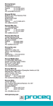
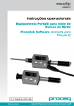
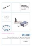
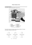
BTIPD HardnessTester USER′S MANUAL V1.0 Please Carefully Read This First Contents Caution……………………………………………………………1 Applicable Standards…………………………………..……2 1. Summarize…………………………………………...............3 1.1 Measuring Principle Scope…………….................................3 1.2 The Hardness Value "L"………………..................................5 1.3 Features…………………………………………………………6 1.4 Applications…….........................................................7 1.5 Primary Industries………………………………………………7 2. Technical Specifications…………………………...……8 3. Overview……………………………………………………..10 4. Checking Supplied Accessories………………….…11 5. Operating Instructions………………………………….14 5.1 Keys and Function…………………………………………....14 5. 2 LCD Screen………………………...…………………………16 5. 3 Setting……………...……………………………….…………17 5.3.1 Material Type………………………………………………..17 5.3.2 Hardness Scale…………………………………………..…18 5.3.3 Data in One Group…………………………………….……20 5.3.4 Browse Data…………...……………………………………20 5.3.5 Setting the Date and Time…………………………..…….22 5.3.6 Calibration…………………………………….……………..23 5.4 The Format of Memory Data……..………………………….27 5.5 Backlight…………………………………………………….....27 5.6 Automatic Shutdown………………………………………….28 5.7 Charging……………………………………………………….28 6. Data Printing………………………………………………..30 7. Hardness Test….............................................................32 7.1 Setting the Tester……………………………………….…....32 7.2 Sample Preparation……………………………………..……32 7.3 Test Steps…………………………………………………….35 8. Troubles and Solutions…………………………………37 9. Maintenance and Service……………………………...38 9.1 Impact Device Maintenance……………………………….38 9.2 Store the Report…………………………….…………………38 9.3 Normal Maintenance Procedures…………………………...39 Appendix 1 Daily Checking………………………….…...40 Appendix 2 Factors that Affect Accuracy…………..41 Appendix 3 Measuring Range……………………….…..44 Caution Please Carefully Read This First 1. Any components of the product cannot be submerged in water and exposed in the rain, which could cause a battery explosion and display unit damage. 2. When stored for a long time, the equipment should be stored in dry environment and used the original packing seal. Environmental temperature: -30°C~+80°C and the relative humidity: 5%~95%. Applicable Standards Standards and Guidelines applied: DIN 50156 (2007), ASTM A956 (2006), GB/T17394 (1998), JB/T 9378 (2001), JJG 747 (1999), DGZfP Guideline MC 1 (2008), VDI/VDE Guideline 2616 Paper 1 (2002), ISO 18625 (2003), CNAL T0299 (2008), JIS B7731 (2000). 1. Summarize 1.1 Measuring Principle Scope When the test is carried out, an impact body with a tungsten carbide test tip is impelled by spring force against a test surface from which it rebounds. Impact and rebound velocities are measured by fallowing method: a permanent magnet integrated into the impact body passes through a coil and induces an electric voltage during its forward and return travel. These voltages are proportional to the velocities and are processed and displayed as the hardness value L on the indicating device. Modern electronics with power saving features provide for Fig. 1-1 long operating life. The large LCD display always shows how the BTIPD is configured to test. Variable function keys allow for quick change of common test parameters. No subjective measuring errors are possible, giving highly repeatable results. Internal self diagnostics with error messages assure reliable test results. Readings can be stored automatically in the internal memory or sent directly to a printer. PC evaluation software allows for data analysis. These conversions to other scales (HRC, HRB, HB, HV, HSD etc.) are programmed into the electronics and can be shown directly on the display as the test result. Release Button Loading Tube Catch Chuck Spring Coil Impact Body Supporting Ring 1.2 The Hardness Value "L" This term, 1978 introduced by Doctor Dietmar Leeb into measuring technology, is the quotient for the impact body's rebound and impact velocity, multiplied by 1000. Harder materials produce higher rebound velocity than those which are less hard. With reference to a particular material group (e.g. steel, aluminum etc.), the L-value represents a direct hardness measurement and is used as such. Comparison curves with standard static hardness values have been established (Brinell, Vickers, Rockwell C, B, Shore D) for the most prevalent materials, enabling the L-value to be converted into the relevant values for these procedures. With BTIPD, such hardness values can be directly displayed in the hardness scales HLD, HRC, HRB, HB, HV, HSD. 1.3 Features The most advanced integrated tester (Impact Device D integrated): no cables Integrated impact direction sensor Highly accuracy (±4HL) in any impact direction (360°) – automatically Integrated display of results for all common hardness scales Large, high contrast LCD for optimum viewing in all conditions Easy calibration Full USB communication with PC, software included free of charge Internal storage of data with day and time Rechargeable Li-ion battery, charges through USB port Intelligent sleep mode Wireless (Bluetooth) mini printer 1.4 Applications Good for all materials Best suited for on-site testing of heavy, big or already installed parts Handy for difficult to access or confined test locations Automatic sensing and compensation for impact direction Excellent for material selection and acceptance tests 1.5 Primary Industries Metal production & processing Automotive & transportation Machinery & power plants Petro-chemical, refineries Aerospace & shipyard Metal constructions testing services & laboratories 2. Technical Specifications Indication range: 0~999HLD Accuracy: ±4HLD Measuring direction: Any direction LCD display: 128 x 64 dot LCD with backlight Data memory: 500 groups Measurement results can be automatically converted into: HB, HRB, HRC, HV, HSD Impact energy: 11N; Mass of the impact body: 5.5g Impact tip: Material: tungsten carbide Diameter: 3mm Hardness: ≥ 1600HV Power: Li-ion rechargeable battery Charger: DC 5V/500mA or USB port Maximum continuous working time: approx. 16 hours Operating environment: Temperature: -10~+60℃ Humidity: 20%~85% Storage environment: Temperature: -30~+80℃ Humidity: 5%~95%. Dimensions: 147 x 35 x 22 mm Weight: 63 g Ref. Fig.3-1 3. Overview 4. Checking Supplied Accessories Make sure you have each items and you can obtain various accessories from your local distributor. (Fig. 4-1) The items are supplied with your hardness tester and the accessories available at your distributor may vary, depending on your country or service provider. Use the purchased accessories with only authorized devices. The use of these accessories with other devices could cause problems and any repair costs would not be covered by the warranty. User’s Manual, Warranty, Certificate etc. Charger for BTIPD Standard block BTIPD Metal Hardness Tester Wireless Mini printer Charger for Printer Carrying Case Little Support Ring, Cleaning Brush etc. Packing List No. 1 2 3 4 5 6 7 8 9 10 11 12 13 14 Description Carrying Case BTIPD Metal Hardness Tester Standard Block Wireless Mini Printer PC Software USB Cable Battery for Printer Charger for BTIPD Charger for Printer Little Support Ring Cleaning Brush User’s Manual Certificate Warranty QTY. 1 1 1 1 1 1 1 1 1 1 1 1 1 1 5. Operating Instructions 5.1 Keys and Function (Fig. 5-1) 1 2 4 3 Fig. 5-1 1. " ": Next, you can use the key to select material, scale etc ; 2. " ": Menu & Select; 3. " ": Print; 4. " 5. " ": ON/OFF & Back; "+" then press " 6. " "+" ": Hardness Calibration; press and hold " ", " for two seconds to display the calibration mode; ": Delete; press and hold " ", then press " " to delete the current data; 7. " "+" and hold " 8. " " "+" ": Set the date and time; In shutdown state, press ", then press" " to set the date and time; ": Data Browse; press and hold " " to enter data browse. ", then press 5.2 LCD Screen Material Impact Times Measurement Value Data in One Group Hardness Scale Battery Capacity Average Value Fig.5-2 5. 3 Setting 5.3.1 Material Type In measurement mode, press " " three times once, the material character will highlight, then press " " to select the Material Type; the material type changed according to following sequence: Steel & Cast steel → Alloy Tool Steel → Stainless Steel → Grey Cast Iron → Ductile Iron → Cast Al Alloys →Cu-Zn Alloys→Cu-Sn Alloys → Copper → Forging Steel → Steel & Cast steel →…. Note: 1. It is necessary to select the material classification. When you did not know the material type, you must refer the related material handbook. 2. When you change the material group, the Impact Times counter will be set to “0”. 5.3.2 Hardness Scale In measure mode, press " twice, the hardness scale " Fig.5-4 character will highlight, then press " " to select the hardness scale; the hardness scale changed according to following sequence: HLD→HB→HRB→HRC→HV→HSD→HLD…. HB Brinell HRB Rockwell HRC Rockwell HV Vickers HSD Shore (D) Note: 1. The value “---” means out of range. 2. The default hardness scale is HLD. Fig. 5-5 5.3.3 Data in One Group In measurement mode, press " " four times, the data in one group character will highlight, then press " " to set the number, the maximum number is 9. 5.3.4 Browse Data ① Browse the data in current group: in measurement mode, press " " once, the impact time character will highlight, then press " ", you can browse the data in current group. (Fig.5-6) ② Browse the historical data: in measurement mode, press and hold " ", then press " " to Fig.5-6 display the historical data browse mode (Fig.5-7), press " " to select the next group, press " " to select the previous group; press " " you can browse the data that you selected (Fig.5-8); press " " to browse the next group, press " " browse the previous group. Fig.5-7 Fig.5-8 Press " " will return to previous menu. 5.3.5 Setting the Date and Time BTIPD has built-in real-time clock, It must be adjusted the clock and the calendar when it is necessary. Please as follows: In shutdown mode, press and Fig. 5-9 hold " ", then press and hold " " for about three seconds to the date and time setting mode. Press " " to increase the "day" from 1 to 31, press " " to decrease the "day" from 31 to 1; press " " to set the month, press " " to increase the "month" from 1 to 12, press " " to decrease the "month" from 12 to 1; use the same way to set the year, hour, minute and second. In the "second" set-up process, press the " " will finish the setting and back to measurement mode. (Fig. 5-9) 5.3.6 Calibration Calibration is used to calibrate the measured value (HLD) of the hardness tester, so as to farthest decrease the measuring error, please as follows: ①In shutdown mode, press and hold " ", then press and hold " " for about three seconds to display the calibration mode (Fig. 5-10), then test five times on the test block and get the average of measurements value. ②Press " " to browse 5 data test, you can press " " to delete the error data. ③Press " " to display the mode like (Fig. 5-11), the “hundred” bit will be highlighted, input the HLD value that marked on test block. ④Press " " to increase from 0 to 9, to set the “hundred” bit. ⑤Press the " "the “ten” bit will be highlighted (Fig.5-12), Press " " to increase from 0 to 9, to set the “ten” bit. ⑥Press the " "the “last” bit will be highlighted (Fig.5-13), Press " " to increase from 0 to 9, to set the “last” bit. ⑦Press " " to return to the measurement mode, the calibration is finish. Note: 1. You must calibrate it on the test block before you first use the hardness tester. 2. The impact direction must be down straight. Fig.5-10 Fig.5-11 Fig.5-12 Fig.5-13 5.4 The Format of Memory Data The data (such as hardness value, scale, sample material and impact direction, time, date etc.) will be saved in memory automatically after one individual impact. BTIPD can store 500 data, when test times are more than 500, the last data will be stored in the 1th position and the first data will be erased, simultaneously the position of other data will be moved into lower position. 5.5 Backlight LED backlight is used for poor light conditions. If there is no impact, or not press any key in 3 seconds, the backlight will be turn off automatically, when testing or press any key, the backlight will be turn on automatically. 5.6 Automatic Shutdown If there is no measure, and no key operation in 3 minutes, display unit will automatically switch off in order to saving battery power. Display unit will automatically store all the parameters before turning-off. 5.7 Charging Users need to recharge batteries when batteries are used for the first time and exhaustion of electricity arises. Firstly, users should connect the BTIPD and the charger use the USB cable (Fig 5-14), and then connect the charger with AC socket Fig.5-14 to start charging. Meanwhile, the screen will display in charging mode. (Fig 5-15). You can also use other USB device (e.g. Laptop) to charge BTIPD. The charging time: 2~3 hours. Fig 5-16 shows the charging is finish. Fig.5-15 Fig.5-16 6. Data Printing BTIPD can be linked with exclusive Bluetooth mini printer, so printer can print out the measured values. The maximum distance between the BTIPD and the printer is three meters. When the printer is turned on, press " " will print out the current data. Fig.6-1 A complete test report is shown at Fig. 6-2. Fig.6-2 7. Hardness Test 7.1 Setting the Tester Press " " to turn on, and check if it’s need to charge. Inspect if every setting of is correctly, particularly the material type and scale. The setting inconsistent with the actual condition may cause a great error. 7.2 Sample Preparation Inappropriate sample will cause a great measurement error. Therefore, users should make the necessary handling and preparation under the original conditions of sample. Preparation of the sample and the surface of test should be coincident with the following basic requirements: 1) During the process of sample surface preparation, users should avoid 2) The sample surface is plane for better, the test surface should be with a metallic sheen, and not involve oxide layer or other stains. 3) Roughness of the test surface Ra ≤ 1.6. 4) Sample must be of sufficient quality and rigidity. If it’s lack of quality and rigidity, it may cause displacement or shaking in the process of testing impact, which can lead to large errors. Generally speaking, if the sample quality is more than 5kg can be directly tested; if the sample quality is 2~5kgs, the sample should be taken in fixation test by means of appropriate clamping; if the sample quality is 0.05~2kgs, the sample should be conducted coupling before the test; if the sample quality is less than 0.05kg, this hardness tester is inappropriate to use. Coupling method: Testing sample’s back should be prepared to make a plane as a supporting surface with a smooth formation. Filling with a now press to the surface of the supporting object (The weight of supporting object should be more than 5 kg, and it can be replaced by test block) to stick into integration. 5) Samples should be thick enough and with sufficient surface absorption layered. The thickness of sample should not be less than 5mm, and surface absorption layer (or surface-hardening layer) should not be less than 0.8mm. To accurately measure the hardness of the material, the best way is to remove the surface-hardening layer by processing. 6) When testing sample surface is not horizontal, the curvature radius of testing and nearby surface should be larger than 30mm, and appropriate supporting ring should be elected and installed. 7) A sample should not be with magnetic; otherwise the signal of the impact device would be seriously interfered by the magnetic, which may cause inaccurate test results. 7.3 Test Steps 1) Loading Simply load BTIPD by sliding the loading tube forward. (Fig.7-1) 2) Place Then place and hold BTIPD on the surface of the test piece at the desired test point. Impact indirection should be vertical with the test of surface. (Fig.7-2) 3) Impact (Measure) Trigger the impact by pressing the release button. The hardness value will be instantaneously displayed. (Fig.7-3) Fig.7-2 Fig.7-1 Fig.7-3 4) Read off the test result Read off the test result from LCD at Fig.7-4. Modern electronics with power saving features provide for long operating life. The large LCD display always shows how the BTIPD is configured to test. Variable function keys allow for quick change of common test parameters. Fig.7-4 No subjective measuring errors are possible, giving highly repeatable results. Internal self diagnostics with error messages assure reliable test results. Readings can be stored automatically in the internal memory or sent directly to a printer. PC evaluation software allows for data analysis. 8. Troubles and Solutions No. Trouble Reasons Solutions 1 No response switched Lack power Charge the battery 2 Abnormally high results Test tip wearing Replace the test tip 3 No test results Coil damage Contact agencies 4 Printer no response Beyond the transmission range In the 3 meters *Other Trouble, please contact with agencies or distributor. 9. Maintenance and Service 9.1 Impact Device Maintenance After using 1000-2000 times, users should clean the catheter of impact device and impact body with nylon brush, and screw off the supporting ring before clean the catheter, and then take out the impact body, rotate the nylon brush into the tube in an anti-clockwise direction, and pull out when touching the bottom. So repeatedly, and then load up the impact body and supporting ring; Users should release the impact body after use. And the lubricant is banned. 9.2 Store the Report Because printing paper is thermal paper, it should be preserved to avoid the heat and direct light. If the print records are necessary to be kept in 9.3 Normal Maintenance Procedures In calibration of the hardness tester, if finding that error is larger than 12HLD, you must be replace the impact ball or impact body, because the reason may be that the impact ball or impact body is wore out to lead to failure in operation. When the hardness tester arises other abnormal phenomena, you should not demolish or adjust any fixed assembly parts, instead, they should complete warranty cards, send them to authorized maintenance department for maintenance. Appendix 1 Daily Checking Normal test block is mainly used for calibrate the hardness tester. The error and the repeatability of the hardness tester should be in the scope defined by the following table. Impact Device D Impact Direction Hardness of Test Block (HL) 750~830 490~570 Error Allowed ±12HLD ±12HLD Repeatability Allowed 12HLD 12HLD Note: 1. Error=HLD-HLD HLD is the average value of 5 values measured on the test block. HLD is the value that marked on test block. 2. Repeatability= HLDmax-HLDmin HLDmax is the maximum value in 5 values that measured on the test block. HLDmin is the minimum value in 5 value measured on the test Appendix 2 Factors that Affect Accuracy Incorrect operation or improper testing conditions would have serious impact on testing accuracy. Following is several common factors affect the accuracy of testing in use for reference: 1) Roughness of sample surface When the impact body impact on the sample, a small pit would arise on the sample surface, so at the same time, should finish the surface of the sample. The more roughness, the less consumption of impact energy whereas the less roughness, the more consumption of impact energy. Accordingly, the roughness of sample testing points on the surface Ra ≤1.6. 2) The shape of sample surface Leeb testing principle demands the velocity of rebound and impact are on the velocity of rebound and impact are not on the same line, it also can show hardness for sure, but the impact body would collide with tube wall when it rebounds, which will affect the velocity of rebound. Therefore, a greater error is on test accuracy. When the radius of curvature of the testing sample surface is smaller, the solution is the use of suitable variant supporting circle. If users require special supporting circle, we can contribute to design and process. 3) The weight of the sample If the sample weight must be larger than or equal to 5kg, and not easily sway. If the sample weight were less, the sample would need proper treatment (It is necessary to increase the supporting or mounting through coupling compress on larger weight testing stand), and the testing results can be achieved in accuracy. There should be a certain area at the testing points (the area required to meet a set of testing points) and no vibration or shaking. If the weight is not enough, users must be as much as possible reduce the jitter and sloshing by the methods of increasing supporting, coupling and compressing. And supporting device should avoid shock. 4) The sample stability Any effective tests need to minimize possible interference from outside; it’s more important to dynamic measure such as Leeb hardness test. Therefore, measuring only allowed in stable hardness testing system. If it’s likely to lead to sample movement in the tests, users should fix it before testing. Appendix 3 Measuring Range Materials HV HB HRC HRB HSD Steel & Cast Steel 81-955 81-654 20.0-68.4 38.4-99.5 32.5-99.5 Alloy Tool Steel 80-898 Stainless Steel 85-802 20.4-67.1 85-655 19.6-62.4 46.5-101.7 Grey Cast Iron 63-336 Ductile Iron 140-387 Cast Aluminum Alloys 19-164 23.8-84.6 Cu-Zn Alloys (Brass) 40-173 13.5-95.3 Cu-Sn Alloys (Bronze) 60-290 Copper Forging Steel 45-315 83-976 142-651 19.8-68.5 59.6-99.6 26.4-99.5