1
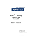
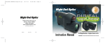
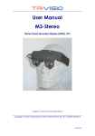
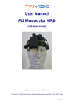
DRV050-CV-R02 Preliminary Spec V0.1 DRV050-CV-R02 SVGA050 CVBS Drive Board User manual Features Multi-format composite video input(default is PAL) Low power consumption Industrial temperature grade Wide power supply Custom Re-configurable Power and consumption General description DRV050-CV-R01 is an analog composite video input Input voltage DC 5~17V driver board for SVGA050 OLED microdisplay. The Typical power 500mW(Include display) low power consumption decoder can automatically consumption detects and converts standard analog baseband television signals compatible with worldwide NTSC, Input video signal PAL, and SECAM standards into digital YCbCr 4:2:2 component video data compatible with the 8-bit ITU-R Video signal Composite video BT.656 interface standard. Default driver board setting Voltage level 0~1.5 Vpp is PAL input, and the resolution is 768×576, support Input resistor 75Ω Output (PAL) 768×576 mono or color signal. The display center is accord to the driver PCB center, Interface (3.3V CMOS standard) convenient for design and set up optical system。 I/O definition Function (active low) The five input pins allow user to adjust the brightness, KEY1 KEY2 KEY1+KEY2 KEY_F PGCLK KEY_F+PGCLK VPP contrast of the display. One CMOS standard serial communication interface allow user to configure all register of the Decoder and Display. So user can re-configure the driver board flexible. Low-noise, low-dropout DC/DC convertor can support 5.5V-17V wide input voltage. Increase Brightness(++) Reduce Brightness(--) Brightness & Contrast Reset Increase Signal Contrast(++) Reduce Signal Contrast (--) On /Off Temp. Compensation Hardware Reset TxD/RxD CMOS 3.3V RS232 interface COM Setting 9600/N/8/1 Mechanic dimension Dimension (L×W) 29mm×29mm Display center is accord to drive PCB center 1 DRV050-CV-R02Preliminary Spec V0.1 Interface and pin definition No. Name Voltage level Function 1 TxD RS232 Send Pin 3.3V 2 RxD RS232 Received Pin 3.3V 3 KEY_F Increase Contrast 3.3V 4 KEY1 Increase Brightness 3.3V 5 KEY2 Reduce Brightness 3.3V 6 PGCLK Reduce Contrast 3.3V 7 PGDATA Resevered 3.3V 8 Reset Reset Key 3.3V 9 GND Power GND 0V 10 Vcc(3.3V) No. Name Function Voltage level 1 CV_GND Signal_GND 3.3V 2 CV+ Signal_IN 3.3V 3 GND Power GND 0V 4 VIN Power IN 5~17V 3.3V Power Output(<50mA) 3.3V Function key description All of the Keys are active low pulse, and must be not less than 20ms. If the low pulse is more than 20ms, MCU will do the same operate continually by every 20ms. KEY1: Only when temperature compensation disabled, Increase Display 19H register value: (19H)++, adjust range is 20H~ FFH. If (19H) less than 20H, then recover to FFH. It’s effect to adjust Display common cathode voltage, and make the Display brightness change from darkest (FFH) to brightest (20H). KEY2:Only when temperature compensation disabled, Decrease Display 19H register value: (19H)--, adjust range is 20H~ FFH. If (19H) less than 20H, then recover to FFH. It’s effect to adjust Display common cathode voltage, and make the Display brightness change from darkest (FFH) to brightest (20H). KEY_F: Increase Display 08H register: (08H) ++, adjust range is 00H~ FFH. It’s effect to adjust the brightness of input video signal, from darkest to brightest. Reg(08H) Output = Input + (Reg(08H) – 80H) Result 00H Signal is the darkest 80H Signal is no change FFH Signal is the brightest 2 DRV050-CV-R02Preliminary Spec V0.1 PGCLK: Decrease Display 08H register: (08H) ++, adjust range is 00H~ FFH. It’s effect to adjust the brightness of input video signal, from darkest to brightest. Reg(08H) Output = Input + (Reg(08H) – 80H) Result 00H Signal is the darkest 80H Signal is no change FFH Signal is the brightest PGCLK+KEY_F: Turn On/Off temperature compensation function. When temperature compensation turn on, every 10s will check the value of Display temperature sensor, and automatic correct the value of Display 19H register, and all the other operate of 19H register will be disabled. KEY1+KEY2:Brightness and contrast return to the initial state (The state before you change the register value). Reset: Hardware reset, all setting will come back to default. Communication description RxD and TxD pin are work in COMS 3.3V standard, it cannot connect to PC RS232 port directly. In order to ensure the MCU to work normally,when the driver board is powered up,the PC port must send a reset command at the same time (02 55 03 00 00 03). Every command must be sending in 600ms and total bytes must be less than 64 bytes, otherwise, will receive the error code. Communication interface support master controller to read/write the register value of Display, Decoder and EEPROM. The change of the Decoder and Display will effect immediately, but when power down or reset, it will lost. The change of the EEPROM is equal to modify the default setting, will effect after power up in next time or reset. Display, Decoder and EEPROM register address range are both 00H~FFH. Driver board’s MCU will not validate the address and values in received command, so please use it be carefully and make reference of the related spec or contact our technical supports. Communication mnemonic symbol Mnemonic Code(Hex) Signification Error Code STX 02h Start symbol Mnemonic Code(Hex) ETX 03h End symbol Err_Head F0h Start symbol error ACK 06h ACK symbol Err_End F1h End symbol error NAK 07h NAK symbol Err_CMD F2h CMD symbol error 00h Read soft version Err_DateLen F3h Data Length error 11h Read Display Err_Frame F4h Frame error 12h Read Decoder Err_FIFO F5h FIFO overflow 13h Read EEPROM Err_RxProc F6h CMD process error 21h Write Display Err_TimeOut F7h CMD timeout 22h Write Decoder Err_Waiting F8h CMD not finished 23h Write EEPROM Err_Unknow FFh Unknown CMD CMD 3 Signification DRV050-CV-R02Preliminary Spec V0.1 Communication command formatting Send: STX + CMD +DataLen + Data + ETX DataLen Response: STX + CMD + DataLen + ACK/NAK + Data + ETX DataLen Command usage 1. Read command (All command are fixed in 6 bytes) Send: STX 02 Succeed Response: STX 02 Error Response: STX 02 CMD 00/11/12/13 Length 03 CMD Length 00/11/12/13 03~FF ErrCode F0~FF ACK 06 Length NAK 02 07 Add0 00~FF Data0 00~FF ReadLen 01~FF …… …… ETX 03 Datan 00~FF ETX 03 ETX 03 Read command examples: Read Display register from 00H to 0FH: Read Decoder register from 00H to 20H: 02 11 03 00 10 03 02 12 03 00 21 03 2. Write Command (6 ≤ Total Bytes ≤ 64) Send: STX 02 CMD Length Add0 Data0 21/22/23 03~3C 00~FF 00~FF Succeed Response: STX 02 CMD 21/22/23 Length 02 ACK 06 ETX 03 Error Response: STX 02 ErrCode F0~FF Length NAK 02 07 ETX 03 …… …… Write command example: Write Display register (01H) = 41H, (19H) = A0H: 02 21 05 01 41 19 A0 03 4 Addn Datan 00~FF 00~FF ETX 03 DRV050-CV-R02Preliminary Spec V0.1 MECHANICAL CHARACTERISTICS 5 DRV050-CV-R02Preliminary Spec V0.1 6