1
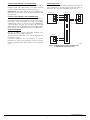
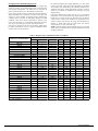
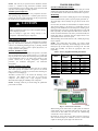
Table 1 – Refrigerant Connections and Recommended Liquid and Vapor Tube Diameters (in.)
LIQUID
Connection DiameTube Diameter
ter
3/8
3/8
3/8
3/8
3/8
3/8
3/8
3/8
3/8
3/8
189BNV
13, 24B*
24A*, 25
36, 37
48, 49
60
Connection Diameter
3/4
3/4
3/4
7/8
7/8
VAPOR†
Max (Rated) Diameter
3/4
7/8
7/8
(1 ---1/8)
(1 ---1/8)
Minimum Tube Diameter
5/8
5/8
5/8
3/4
3/4
* *24A unit height is 38--- 7/16”, 24B unit height is 31--- 5/8
{ Units are rated with 25 ft. (7.6 m) of lineset. See Product Data sheet for performance data when using different size and length line sets.
Notes:
1. Do not apply capillary tube indoor coils to these units.
Step 7 — Make Electrical Connections
Evacuate Refrigerant Tubing and Indoor Coil
CAUTION
!
WARNING
!
UNIT DAMAGE HAZARD
ELECTRICAL SHOCK HAZARD
Failure to follow this caution may result in equipment
damage or improper operation.
Failure to follow this warning could result in personal
injury or death.
Never use the system compressor as a vacuum pump.
Do not supply power to unit with compressor terminal box
cover removed.
Refrigerant tubes and indoor coil should be evacuated using the
recommended deep vacuum method of 500 microns. The alternate
triple evacuation method may be used. See Service Manual for
triple evacuation method. Always break a vacuum with dry
nitrogen prior to opening the refrigerant system for servicing.
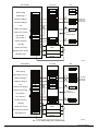
Deep Vacuum Method
The deep vacuum method requires a vacuum pump capable of
pulling a vacuum of 500 microns and a vacuum gauge capable of
accurately measuring this vacuum depth. The deep vacuum method
is the most positive way of assuring a system is free of air and
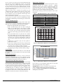
liquid water. (See Fig. 4)
5000
4500
Be sure field wiring complies with local and national fire, safety,
and electrical codes, and voltage to system is within limits shown
on unit rating plate. Contact local power company for correction of
improper voltage. See unit rating plate for recommended circuit
protection device.
NOTE: Operation of unit on improper line voltage constitutes
abuse and could affect unit reliability. See unit rating plate. Do not
install unit in system where voltage may fluctuate above or below
permissible limits.
NOTE: Use copper wire only between disconnect switch and unit.
NOTE: Install branch circuit disconnect of adequate size per NEC
to handle unit starting current. Locate disconnect within sight from
and readily accessible from unit, per Section 440--14 of NEC.
Route Ground and Power Wires
4000
3500
3000
2500
Remove access panel to gain access to unit wiring. Extend wires
from disconnect through power wiring hole provided and into unit
control box.
MICRONS
LEAK IN
SYSTEM
WARNING
!
2000
1500
1000
500
0
1
2
3
4
5
MINUTES
VACUUM TIGHT
TOO WET
ELECTRICAL SHOCK HAZARD
TIGHT
DRY SYSTEM
Failure to follow this warning could result in personal injury
or death.
6
7
The unit cabinet must have an uninterrupted or unbroken
ground to minimize personal injury if an electrical fault
should occur. The ground may consist of electrical wire or
metal conduit when installed in accordance with existing
electrical codes.
A95424
A95424
Fig. 4 -- Deep Vacuum Graph
Final Tubing Check
IMPORTANT: Check to be certain factory tubing on both indoor
and outdoor unit has not shifted during shipment. Ensure tubes are
not rubbing against each other or any sheet metal. Pay close
attention to feeder tubes, making sure wire ties on feeder tubes are
secure and tight.
Connect Ground and Power Wires
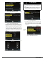
Connect ground wire to ground connection in control box for
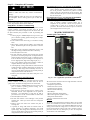
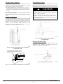
safety. Connect power wiring to contactor as shown in Fig. 5.
DISCONNECT
PER N. E. C. AND/OR
LOCAL CODES
TERMINAL
BLOCK
FIELD POWER
WIRING
FIELD GROUND
WIRING
GROUND
LUG
Fig. 5 -- Line Power Connections
A14028
Catalog No: II189BNV--- 04
Manufacturer reserves the right to change, at any time, specifications and designs without notice and without obligations.
5
Replaces: II189BNV--- 03