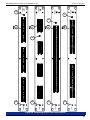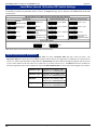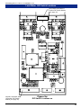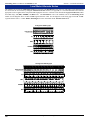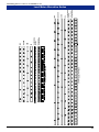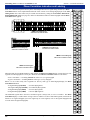
1
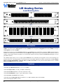
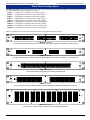
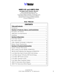
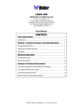
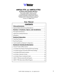
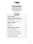
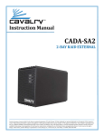
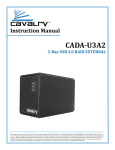
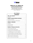
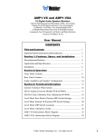
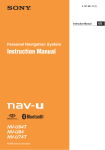
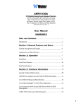
LM Analog Series
Level Meter Units
Two, Four, Six, Eight or Twenty-Four Channel
with 30, 53, 60 or 106-Segment
LED Bargraph Level Meters
Document P/N 821604 Rev-B
User Manual
CONTENTS
Title and Contents .................................................................. 1
Introduction....................................................................................... 2
Section 1: General Features and Specifications......... 3
Description and Features
.................................................................. 4
Applications and Specifications ......................................................... 5
Rear Panel Configurations.................................................................. 6
Front Panel Configurations................................................................. 7
Section 2: Operation .............................................................. 9
Installation
...................................................................................... 11
Front Panel Features
........................................................................ 12
Rear Panel Features .......................................................................... 14
Section 3: Technical Information ..................................... 17
Level Meter Internal 10-Position DIP Switch Settings .......................... 18
Level Meter DIP Switch Locations ..................................................... 19
Level Meter Alternate Scales ............................................................ 20
Phase Correlation Indication and Labeling .......................................... 22
LM53 and LM106 Interconnect Block Diagrams ................................. 23
LM30 and LM60 Interconnect Block Diagrams ................................... 24
© 2006 Wohler Technologies Inc. ALL rights reserved
Important Safety Instructions
1)
Read these instructions.
2)
Keep these instructions.
3)
Heed all warnings.
4)
Follow all instructions.
5)
Do not use this apparatus near water.
6)
Clean only with dry cloth.
7)
Do not block any ventilation openings. Install in accordance with the manufacturer's instructions.
8)
Do not install near any heat source such as radiators, heat registers, stoves, or other apparatus (including
amplifiers) that produce heat.
9)
Do not defeat the safety purpose of the polarized or grounding-type plug. A polarized plug has two blades
with one wider than the other. A grounding type plug has two blades and a third grounding prong. The
wide blade or the third prong are provided for your safety. If the provided plug does not fit into your outlet,
consult an electrician for replacement of the obsolete outlet.
10) Protect the power cord from being walked on or pinched, particularly at plugs convenience receptacles
and the point where they exit from the apparatus.
11) Only use attachments/accessories specified by the manufacturer.
12) Use only with the cart stand, tripod, bracket, or table specified by the manufacturer, or sold with the
apparatus. When a cart is used, use caution when moving the cart/apparatus combination to avoid injury
from tip-over.
13) Unplug this apparatus during lightning storms or when unused for long periods of time.
14) Refer all servicing to qualified service personnel. Servicing is required when the apparatus has been
damaged in any way, such as when power-supply cord or plug is damaged, liquid has been spilled or
objects have fallen into the apparatus, the apparatus has been exposed to rain or moisture, does not
operate normally, or has been dropped.
15) Do not expose this apparatus to rain or moisture.
16) The apparatus shall be connected to a mains socket outlet with a protective earthing connection.
CAUTION!
In products featuring an audio amplifier and speakers, the surface at the side of the
unit, where the audio amplifier heat sink is internally attached, may get very hot after
extended operation. When operating the unit excercise caution when touching this
surface and ensure that external materials which may be adversely affected by heat
are not in contact with it. There is a Hot Surface label (see diagram) attached to the
aforementioned surface of the product.
Introduction
Congratulations on your selection of a Wohler Technologies product. We are confident it represents the best performance and value
available, and we guarantee your satisfaction with it.
If you have questions or comments you may contact us at:
Wohler Technologies, Inc.
31055 Huntwood Avenue
Hayward, CA 94544
Phone: (510) 870-0810
Fax: (510) 870-0811
US Toll-Free: 1-888-596-4537
www.wohler.com
2
[email protected]
© 2007 Wohler Technologies, Inc. ALL rights reserved
LM Analog Series User Manual P/N 821604 Rev-B
Section 1
General Features
and Specifications
Description
Features
Applications
Specifications
Congurations
Rear Panel Configurations
Front Panel Configurations
© 2006 Wohler Technologies Inc. ALL rights reserved
3
Section 1: General Features and Specifications
LM Analog Series User Manual P/N 821604 Rev-B
LM Analog Series
Level Metering Units
1
3
2
4
LM30-4
WOHLER
TECHNOLOGIES
LM30-4
1
LM60-2
WOHLER
TECHNOLOGIES
2
LM60-2
WOHLER
TECHNOLOGIES
1
15
12
15
12
15
12
15
12
15
12
15
12
15
12
15
12
15
12
15
12
15
12
15
12
8
6
4
2
0
2
8
6
4
2
0
2
8
6
4
2
0
2
8
6
4
2
0
2
8
6
4
2
0
2
8
6
4
2
0
2
8
6
4
2
0
2
8
6
4
2
0
2
8
6
4
2
0
2
8
6
4
2
0
2
8
6
4
2
0
2
8
6
4
2
0
2
6
6
6
6
6
6
6
6
6
6
6
6
10
12
15
18
22
26
30
35
40
50
10
12
15
18
22
26
30
35
40
50
10
12
15
18
22
26
30
35
40
50
10
12
15
18
22
26
30
35
40
50
10
12
15
18
22
26
30
35
40
50
10
12
15
18
22
26
30
35
40
50
10
12
15
18
22
26
30
35
40
50
10
12
15
18
22
26
30
35
40
50
10
12
15
18
22
26
30
35
40
50
10
12
15
18
22
26
30
35
40
50
10
12
15
18
22
26
30
35
40
50
10
12
15
18
22
26
30
35
40
50
2
3
4
5
6
7
8
9
10
11
12
13
14
15
16
17
18
19
20
21
22
23
POWER
LM53-24
24
LM53-24
WOHLER
TECHNOLOGIES
1
3
5
2
4
6
LM106-6
LM106-6
Description
Wohler Technologies line of 1U and 2U analog audio level metering units provide from one to twelve pairs of 53-segment level meters
(LM53), one to three pairs of 106-segment level meters (LM106), one to two pairs of 30-segment level meters (LM30), or one pair
of 60-segment level meters (LM60).
Standard input connectors for the LM Analog Series are "mini" Phoenix type terminal block connectors. XLR connector inputs are
available as a custom option for all versions except the LM53-24. Input connector type is determined by the customer at time of
ordering. Analog input connector impedances are 27 K Ω (ohm), balanced, and may be adjusted for Reference Level gain via a rear
panel DIP switch(es).
The standard display mode is set as a single segment PPM ‘dot’ above a VU bar; each segment’s color is fixed according to its
position on the scale. Each bargraph meter section (pair) may be individually adjusted for a number of parameters, including Display
Mode, Peak Hold, PPM Ballistics, Alternate Scales, and Phase Correlation via rear panel and internal DIP switches. An Auto
Line Level Calibrate feature is also available.
Features
• 30, 60, 53 or 106-segment tri-color bargraph level meters provide wide dynamic range
• Selectable input Referrence Level (0, +4, +6, or +8 dBfs)
• Selectable Display Mode (VU Only, VU/PPM, or PPM Only)
• Selectable Peak Hold (Manual, 3-Second, 10-Second, or Off)
• Selectable PPM Ballistics (Type I, Type II, DIN 45406, or SSRT)
• Selectable Phase Correlation feature (on/off)
• Selectable alternate Bargraph Scales (Extended VU, VU, BBC, NORDIC, DIN, and CUSTOM)
• Front panel bargraph brightness control
4
© 2006 Wohler Technologies Inc. ALL rights reserved
Section 1: General Features and Specifications
LM Analog Series User Manual P/N 821604 Rev-B
Applications
The LM Analog series of level metering units are an adaptable and effective way to monitor any analog audio application. The following
are some of the applications where an LM Series unit would prove valuable.
·
Cinema
·
Radio Broadcast Station
·
Theatrical Staging
·
TV Control Room
·
Music Design Application
·
Mobile Broadcast unit
·
Broadcasting Schools
·
Remote Radio Station
·
Home Theater
·
Sound Staging development
·
Any Aural Media applications
·
Recording Studio
Specifications
Level Meter Type:
LED bargraph
Segment Quantity:
Small Segments: LM53 = 53, LM106 = 106
Large Segments: LM30 = 30, LM60 = 60
Level Gain (DIP switch selectable):
0, +4, +6, +8 dB
Bargraph Length:
LM53 =
LM106 =
LM30 =
LM60 =
LED Segment Size:
LM53 & LM106 = 0.14" x 0.028" (3.57 x 0.7 mm)
LM30 & LM60 = 0.305" x 0.152" (7.75 x 3.86 mm)
LED Segment Pitch:
LM53 & LM106 = 0.041" (1.05 mm)
LM30 & LM60 = 0.2" (5.08 mm)
Segment Display Color:
Tri-color (red, amber, green)
Peak Emmision Wavelength:
Green: 570 nm, Red: 630 nm
Segment Brighness, (If = 20 mA):
LM53 & LM106 = 3.5 mcd
LM30 & LM60 = 5.5 mcd
Segment Brightness, Uniformity:
LM53 & LM106 = <10% difference between segments
LM30 & LM60 = <8% difference between segments
2.22" (56.4 mm)
4.44" (56.4 mm)
6" (56.4 mm)
12" (56.4 mm)
Adjacent Segment "Off" Brightness: <1% of brightness of active segment
Dynamic Range,
Extended VU (Standard Analog) Scale:
LM30 = 65 dB, LM60 = 66.5 dB
LM53 = 66 dB, LM106 = 72 dB
Midscale Resolution,
Extended VU (Standard Analog) Scale:
LM30 & LM53 = 1 dB
LM60 & LM106 = 0.5 dB
Analog Full Scale Input:
+24 dBv
Input Sampling Rate:
>=48 kHz
Analog Input Impedance:
27k Ω (Ohm), balanced
Input Connectors:
"mini" Phoenix, female (Standard)
AC Mains Power:
100-250 VAC, 50/60 Hz universal input, auto-switch
Power Consumption:
25 watts (1U) or 40 watts (2U) maximum
Dimensions:
1U = 3.5 x 19 x 8" (89 x 483 x 203 mm)
2U = 1.75 x 19 x 8" (44 x 483 x 203 mm)
Weight:
1U = 8 lbs (3.5 kg)
2U = 12 lbs (5 kg)
Units are certified to meet, at time of manufacture, all currently applicable product safety and EMC requirements, such as those of CE. 0 dbv ref.
0.775V RMS. Features and specifications subject to improvement without notice.
© 2006 Wohler Technologies Inc. ALL rights reserved
5
LM Analog Series User Manual P/N 821604 Rev-B
Section 1: General Features and Specifications
Rear Panel Configurations
The 1U rear panels are comprised of modular panel sections. One to two of the modular panel sections have the audio input connectors
(and DIP switch module), with any remaining sections being a blank panel. This arrangement permits mixing of different types of input
modules, although such mixes are considered special order items.
1U Rack Model Rear Panels
CH A
CH B
CALIB
Figure-1a (below) shows the standard 4-channel input section with the "mini" Phoenix connectors available for use in the 1U LM
Analog models.
CH A
CH B
3-4
1-2
FIGURE-1a:
4-Channel Input Section
with Mini-Phoenix Connectors
(standard)
The two rear panel illustrations below show the standard rear panel configurations for an 8-channel LMxx-8 model (top) and a 2channel LMxx-2 model (bottom) in the LM Analog series. For models featuring a different quantity of inputs, the rear panel would
have a different quantity of input sections and/or connectors.
INTERNAL POWER
CH B
CH A
CH B
7-8
CH A
5-6
CH B
CALIB
CH A
CALIB
UNDERWRITERS LABS
SEE POWER SUPPLY
LABEL ON SIDE
CH A
CH B
3-4
1-2
LMxx-8 Rear Panel (8-Channel)
INTERNAL POWER
CH A
CH B
CALIB
UNDERWRITERS LABS
SEE POWER SUPPLY
LABEL ON SIDE
CH A
CH B
1-2
LMxx-2 Rear Panel (2-Channel)
2U Rack Model Rear Panel
CH 7
CH 8
CH A
CH B
CH B
CH 10
CH 3
CH 4
CH A
CH B
CH A
CH B
HI
LO
CH 9
CH 1
CH 2
CH A
CH B
HI
LO
1 2 3 4 5 6
HI
LO
HI
LO
HI
LO
HI
LO
CH 6
CH A
HI
LO
CH B
HI
LO
CH A
HI
LO
HI
LO
CH 11 CH 12
HI
LO
CH B
CH 5
1 2 3 4 5 6
1 2 3 4 5 6
HI
LO
HI
LO
CH B
HI
LO
CH A
HI
LO
HI
LO
CH 17 CH 18
1 2 3 4 5 6
HI
LO
CH A
HI
LO
CH B
CALIB
CH A
CH 13 CH 14
HI
LO
CH B
HI
LO
CH A
CALIB
CH 15 CH 16
CALIB
CH B
1 2 3 4 5 6
HI
LO
HI
LO
HI
LO
100-240 VAC
50/60 Hz
CH 19 CH 20
SERIAL
NUMBER
CH A
1 2 3 4 5 6
INTERNAL POWER
UNDERWRITERS LABS
SEE POWER SUPPLY
LABEL ON SIDE
CH 21 CH 22
HI
LO
CH B
CALIB
CH A
CALIB
CH 23 CH 24
CALIB
The rear panel illustration below shows the 2U size rear panel for the LM53-24 model, which is NOT comprised of modular panel
sections (as are the 1U rear panels). This rear panel is available only with "mini" Phoenix connectors.
LM53-24 Rear Panel (Twenty Four-Channel with "Mini" Phoenix Connectors)
6
© 2006 Wohler Technologies Inc. ALL rights reserved
LM Analog Series User Manual P/N 821604 Rev-B
Section 1: General Features and Specifications
Front Panel Configurations
The LM Analog Series of level mertering units come with a variety of different bargraph sizes and quantities. The following list shows
the standard front panel model configurations available:
LM30-2: 1 Bargraph Pair (2 channels) with 30 large segments
LM30-4: 2 Bargraph Pairs (4 channels) with 30 large segments
LM60-2: 1 Bargraph Pair (2 channels) with 60 large segments
LM53-4: 2 Bargraph Pairs (4 channels) with 53 small segments
LM53-8: 4 Bargraph Pairs (8 channels) with 53 small segments
LM53-24: 12 Bargraph Pairs (24 channels) with 53 small segments
LM106-2: 1 Bargraph Pair (2 channels) with 106 small segments
LM106-4: 2 Bargraph Pairs (4 channels) with 106 small segments
LM106-6: 3 Bargraph Pairs (6 channels) with 106 small segments
Below are examples of five of the nine standard front panel configurations that can be ordered.
WOHLER
TECHNOLOGIES
1
3
5
2
4
6
LM106-6
LM106-6 Front Panel
1U Six-Channel Analog Level Meter unit with 106-Segment Bargraphs (available in standard 2, 4 and 6-channel)
1
3
5
7
2
4
6
8
LM53-8
WOHLER
TECHNOLOGIES
LM53-8 Front Panel
1U Eight-Channel Analog Level Meter unit with 53-Segment Bargraphs (available in standard 4, 6, and 8-channel)
1
LM60-2
WOHLER
TECHNOLOGIES
2
LM60-2 Front Panel
1U Two-Channel Analog Level Meter unit with 60-Segment Bargraphs
1
3
2
4
LM30-4
WOHLER
TECHNOLOGIES
LM30-4 Front Panel
1U Four-Channel Analog Level Meter unit with 30-Segment Bargraphs (available in standard 2 and 4-channel)
WOHLER
TECHNOLOGIES
1
15
12
15
12
15
12
15
12
15
12
15
12
15
12
15
12
15
12
15
12
15
12
15
12
8
6
4
2
0
2
8
6
4
2
0
2
8
6
4
2
0
2
8
6
4
2
0
2
8
6
4
2
0
2
8
6
4
2
0
2
8
6
4
2
0
2
8
6
4
2
0
2
8
6
4
2
0
2
8
6
4
2
0
2
8
6
4
2
0
2
8
6
4
2
0
2
6
6
6
6
6
6
6
6
6
6
6
6
10
12
15
18
22
26
30
35
40
50
10
12
15
18
22
26
30
35
40
50
10
12
15
18
22
26
30
35
40
50
10
12
15
18
22
26
30
35
40
50
10
12
15
18
22
26
30
35
40
50
10
12
15
18
22
26
30
35
40
50
10
12
15
18
22
26
30
35
40
50
10
12
15
18
22
26
30
35
40
50
10
12
15
18
22
26
30
35
40
50
10
12
15
18
22
26
30
35
40
50
10
12
15
18
22
26
30
35
40
50
10
12
15
18
22
26
30
35
40
50
2
3
4
5
6
7
8
9
10
11
12
13
14
15
16
17
18
19
20
21
22
23
POWER
LM53-24
24
LM53-24 Front Panel
2U Twenty Four-Channel Analog Level Meter unit with 53-Segment Bargraphs
© 2006 Wohler Technologies Inc. ALL rights reserved
7
LM Analog Series User Manual P/N 821604 Rev-B
(This page left intentionally blank)
8
© 2006 Wohler Technologies Inc. ALL rights reserved
LM Analog Series User Manual P/N 821604 Rev-B
Section 2
Operation
Installation
Front Panel Features
Rear Panel Features
© 2006 Wohler Technologies Inc. ALL rights reserved
9
LM Analog Series User Manual P/N 821604 Rev-B
(This page left intentionally blank)
10
© 2006 Wohler Technologies Inc. ALL rights reserved
Section 2: Operation
Section 2: Operation
LM Analog Series User Manual P/N 821604 Rev-B
Installation
Mounting
The unit should be mounted where convenient for operating persons, ideally at approximately eye level for best viewing.
Heat Dissipation
Heat produced by these units is negligible. No special considerations for cooling are necessary as long as the ambient temperature
inside the rack area does not exceed approximately 40°C (104°F).
Mechanical Bracing
The chassis is securely attached to the front panel at six points along its surface, not just at the four corners of the chassis ears. This
feature will reduce or eliminate rear bracing requirements in most mobile/portable applications. The weight of internal components is
distributed fairly evenly around the unit.
Audio Connections
Connection of the audio feeds is straightforward. The system interconnect block diagrams located on pages 23 and 24 may be
referred to for clarification of the general signal paths into the LM Analog Series units.
Electrical Interference
As with any audio equipment, maximum immunity from electrical interference requires the use of shielded cable; however, satisfactory results can sometimes be obtained without it. The internal circuitry common is connected to the chassis.
AC Power
The unit's AC mains connection is via a standard IEC inlet, with safety ground connected directly to the unit's chassis. The universal
AC input (100-240VAC, 50/60 Hz) switching power supply is a self-resetting sealed type, with automatic over-voltage and overcurrent shutdown. There is no user-replaceable fuse in either the primary or secondary circuit.
Level Meter Parameter Settings
The Peak Hold, PPM Ballisatics, and Alternate Scale level meter settings are selected using a DIP switch accessable only by
removing the top cover of the unit. Should the user wish to change these settings, it should be done before installation into an
enclosed rack or difficult to access area. See page 18 for setting information.
The Reference Level Gain calibration and the bargraph Display Mode settings may be selected after installation via the DIP
switch(es) on the rear panel as long as the rear panel is easily accessable. If installation makes the rear panel difficult to access, then
these adjustments should be made before installation. See page 14 for setting information.
© 2006 Wohler Technologies Inc. ALL rights reserved
11
LM Analog Series User Manual P/N 821604 Rev-B
Section 2: Operation
Front Panel Features
Please refer to Figure-2a on the following page to familiarize yourself with the front panel features of the LM Analog Series units.
The following sections describe these functions and are referenced, by number, to Figure-2a.
Note: The following feature descriptions are applicable across the entire range of available models. The four models shown are used to
illustrate the four different bargraph types available in the LM Analog Series.
1
Bargraph Brightness Control
2
Audio Level Meters
This control is recessed into the front panel and can be accessed using a small flathead screwdriver. Turning it clockwise will
increase the relative brightness of the bargraph LED segments. Adjusting this one control will simultaneously affect the
brightness of all bargraph displays on the front panel.
Audio levels for the source channels are displayed via pairs of tri-color LED bargraph meters. Each pair represents two
channels. There are four bargraph types available in the LM Analog Series; 30, 53, 60, and 106-segment. All bargraph LED
segments are of the tri-color type (green, amber, red) and are user adjustable for Referrence Level, Display Mode, Peak
Hold, PPM Ballistics, and Alternate Bargraph Scales via DIP switches on the rear panel and inside the unit. See pages 14
and 18 for more information regarding level meter DIP switch settings.
2a
30-Segment LED Bargraph Display (Large LED Segments)
The 30-segment type of tri-color LED bargraph display has a total horizontal length of 6" and features relatively large
LED segments, which are easy to visually monitor from distances of six to thirty feet.
2b
60-Segment LED Bargraph Display (Large LED Segments)
The 60-segment type of tri-color LED bargraph display has a total horizontal length of 12" and features relatively
large LED segments, which are easy to visually monitor from distances of six to thirty feet.
2c
53-Segment LED Bargraph Display (Small LED Segments)
The 53-segment type of tri-color LED bargraph display has a total length of 2.24" and features relatively small highresolution LED segments, which are easy to visually monitor for distances up to six feet.
2d
3
106-Segment LED Bargraph Display (Small LED Segments)
The 106-segment type of tri-color LED bargraph display has a total length of 4.42" and features relatively small highresolution LED segments, which are easy to visually monitor for distances up to six feet.
Power Indication - Green LED
This Power Indication LED signals the operating condition of the power supply. The LED glows GREEN to indicate the LM
Analog Series unit is connected to mains power and an operation voltage is present.
12
© 2006 Wohler Technologies Inc. ALL rights reserved
Section 2: Operation
LM Analog Series User Manual P/N 821604 Rev-B
WOHLER
TECHNOLOGIES
1
WOHLER
TECHNOLOGIES
WOHLER
TECHNOLOGIES
WOHLER
TECHNOLOGIES
1
1
3
7
4
5
2
3
1
1
8
5
6
3
6
4
1
4
2
2
1
2
2a
2b
2c
2d
1
3
3
3
3
LM30-4
LM60-2
LM53-8
LM106-6
Figure-2a: LM Analog Series Front Panel Features
© 2006 Wohler Technologies Inc. ALL rights reserved
13
LM Analog Series User Manual P/N 821604 Rev-B
Section 2: Operation
Rear Panel Features
Please refer to Figure-2b on the following page to familiarize yourself with the rear panel features of the LM Analog Series units. The
following sections describe these features and are referenced, by letter, to Figure-2b. Note that the features descibed below are
applicable across the entire range of available models, and not just the models shown.
A
B
Analog Input Connectors
These 3-pin male “mini” Phoenix connectors accept standard Analog audio signals and are configured for balanced connections
(27 k Ω impedance ). Other connector types are available as special order items.
DIP Switch - Rear Panel
This DIP switch sets the Line Level Calibration, Reference Level, and PPM/VU Display Mode. See the descriptions and
diagram below for setting information.
Line Level (Auto) Calibration:
The unit is calibrated at the factory. To recalibrate:
1) Turn on the power.
2) Apply the desired reference level (nominal 0) signal to all channels.
3) Make sure the Reference Level DIP sections (2 and 3) are set to the nearest level of the input signal being applied for
calibration (i.e., 0, +4, +6 or +8). The user should make sure that the signal applied to all four channels is within +/- 4 dB of
the reference level selected by DIP switch sections 2 and 3.
4) Place DIP section 1 in the DOWN position.
5) Wait 10 seconds. The unit will remove the previous calibration and the new calibration will be applied.
6) Place DIP section 1 in the UP position and return unit to service.
7) Only ONE auto-calibration attempt may be made for each cycling of AC power to the unit. Once the Line Level
Calibration DIP switch has been placed in the CAL position, it is necessary to cycle the power before that DIP switch will
be functional again, EVEN if a calibration attempt was unsuccessful.
If one wishes to calibrate again, turn off the power to the unit and repeat steps 1 through 6.
LEVEL METER CALIBRATION NOTE: For more accurate indication of signal levels, meters are tuned to effect a
“rounding” function, which occurs BETWEEN the thresholds of any two bargraph segments. This means the level meter zero
LED segment will turn on before that segment’s scale indication, the amount being one-half the smallest spacing between LED
segments (mid-scale resolution) or 0.5 dBu, whichever is smallest. For example, using the Analog (extended VU) scale, a
meter calibrated for a +4 dBu nominal level will actually turn the zero LED segment of the level meter on at 3.5 dBu and all
segments will turn on at 0.5 dBu before each segment’s silk-screened scale indication.
Reference Level:
DIP switch sections 2 and 3 determine the Reference Level, which adjusts the level of the input signal and the resultant level
displayed on the LED bargraphs. Factory setting is +4 dB. See DIP switch diagram below for settings.
Bargraph Display Mode:
DIP switch sections 4 and 5 determine how peak levels are displayed for the associated meters on the front panel. There are
four possible settings; VU Only, VU-PPM Floating Segment, PPM Only, and PPM-PPM Floating Segment. The VU
Only selection has a VU floating segment when a Peak Hold value is selected using the Internal 10-Position DIP Switch
Module (see page 18). The factory default setting is VU-PPM Floating Segment. See diagam below for settings.
LM Analog Series Rear Panel DIP Switch Settings
Meter Calibration
1
Display Mode
Reference Level
23
x
45 x
x
Calibrate
Operate
123456
+8 dB
VU Only
+6 dB
VU-PPM Floating Segment
+4 dB
PPM Only
Not Used
0 dB
123456
123456
Note: Position-6 of DIP switch is not functional
C
Power Connector
Attach a standard IEC-320 power cord between this connector and mains power (100 - 240VAC nominal, 50/60 Hz). The
front panel power LED (Item 3) will glow green to indicate operating voltages are present.
14
© 2006 Wohler Technologies Inc. ALL rights reserved
7-8
CH A
CH B
CH A
CH B
100-240 VAC
50/60 Hz
CH B
5-6
1-2
3-4
A
CH A
CH B
CH A
1 2 3 4 5 6
1 2 3 4 5 6
CH B
1-2
CH A
CH B
CH 15 CH 16
CH B
CH B
CH A
CH 21 CH 22
CH A
CH 11 CH 12
CH B
CH 17 CH 18
CH A
1 2 3 4 5 6
1 2 3 4 5 6
CH A
CH 7
CH B
CH 8
CH 4
CH B
CH 3
CH A
CH 10
CH 13 CH 14
CH 9
CH B
CH B
CH A
CH A
1 2 3 4 5 6
1 2 3 4 5 6
CH A
CH 5
CH B
CH 6
CH B
CH 2
CH A
CH 1
INTERNAL POWER
UNDERWRITERS LABS
SEE POWER SUPPLY
LABEL ON SIDE
INTERNAL POWER
UNDERWRITERS LABS
SEE POWER SUPPLY
LABEL ON SIDE
15
© 2006 Wohler Technologies Inc. ALL rights reserved
CH B
CH A
CH 23 CH 24
CH B
CH 19 CH 20
CH A
CALIB
B
CALIB
CALIB
CALIB
CALIB
INTERNAL POWER
CH A
HI
LO
HI
LO
UNDERWRITERS LABS
SEE POWER SUPPLY
LABEL ON SIDE
CH B
C
SERIAL
NUMBER
CH A
HI
LO
HI
LO
HI
LO
HI
LO
HI
LO
HI
LO
HI
LO
HI
LO
HI
LO
HI
LO
HI
LO
HI
LO
HI
LO
HI
LO
HI
LO
HI
LO
HI
LO
HI
LO
HI
LO
HI
LO
CALIB
CALIB
HI
LO
HI
LO
LMxx-8
LM53-24
LMxx-2
CALIB
CALIB
Section 2: Operation
LM Analog Series User Manual P/N 821604 Rev-B
Figure-2b: LM Analog Series Rear Panel Features
LM Analog Series User Manual P/N 821604 Rev-B
(This page left intentionally blank)
16
© 2006 Wohler Technologies Inc. ALL rights reserved
Section 2: Operation
LM Analog Series User Manual P/N 821604 Rev-B
Section 3
Technical Information
Level Meter Internal 10-Position DIP Switch Settings
Level Meter DIP Switch Locations
Level Meter Alternate Scales
Phase Correlation Indication and Labeling
LM53 and LM106 Interconnect Block Diagrams
LM30 and LM60 Interconnect Block Diagrams
© 2006 Wohler Technologies Inc. ALL rights reserved
17
Operation
LM Analog Series User Manual P/N 821604 Rev-B
Level Meter Internal 10-Position DIP Switch Settings
This 10-position DIP switch is accessed by removing the top cover of the LM unit and is located on the 919174 PCB (the same PCB
on which the 6-position rear panel DIP switch is located). See Figure-3a, page 19 for a diagram of the 919174 PCB and the DIP
switch location.
LM Analog Series Level Meter Internal 10-Position DIP Switch Settings
Peak Hold (Bargraph Display)
Scale Selection
x 2 3 4
x
x 2 3 4
AES Scale
(Digital Models ONLY)
x
x 2 3 4
x 2 3 4
x 2 3 4
1 2 3 4 5 6 7 8 9 10
x
1 2 3 4 5 6 7 8 9 10
x 2 3 4
x
1 2 3 4 5 6 7 8 9 10
7 8
x
IEC268-10, Type 1
1 2 3 4 5 6 7 8 9 10
x
x
7 8
x
Peak Hold - 3 Second
1 2 3 4 5 6 7 8 9 10
Alternate AES Scale
(Digital LM26 & LM30
ONLY)
5 6
x
Legacy Ext. VU Scale
(LM30 & LM60 Only)
IEC268-10, Type 2
1 2 3 4 5 6 7 8 9 10
x
x
7 8
x
Peak Hold - 10 Second
1 2 3 4 5 6 7 8 9 10
5 6
x
x
BBC Scale
1 2 3 4 5 6 7 8 9 10
5 6
x
DIN Scale
VU Scale
x 2 3 4
1 2 3 4 5 6 7 8 9 10
1 2 3 4 5 6 7 8 9 10
x
PPM Ballistics (Bargraph Display)
x
x
Peak Hold - Manual
x
Extended VU Scale
(Standard Analog)
1 2 3 4 5 6 7 8 9 10
5 6
NORDIC Scale
1 2 3 4 5 6 7 8 9 10
1 2 3 4 5 6 7 8 9 10
x 2 3 4
x
x
DIN 45406
1 2 3 4 5 6 7 8 9 10
x
x
7 8
x
Peak Hold - Off
1 2 3 4 5 6 7 8 9 10
1 2 3 4 5 6 7 8 9 10
Single Sample Rise
Time (SSRT)
(Digital Models ONLY)
Phase Correlation Display
x
9 x
x
9 x
PC On
1 2 3 4 5 6 7 8 9 10
PC Off
1 2 3 4 5 6 7 8 9 10
Note: Switch positions 1 and 10 are NOT used and should be left at the factory setting.
PPPM Characteristics (Ballistics):
The PPM characteristics determine the Integration Time (rise time) and Return Time (fall time) of the level meter. The
Integration Time is the time it takes for the lighted segments of the level meter, after application of a 5 Khz tone at a certain reference
level, to rise within a specified number of dB of that level. Return Time is the time it takes for the lighted segments of the level meter
to fall a certain number of dB after removal of a 5 Khz tone of a certain reference level. The PPM characteristics available for
selection using DIP switch sections 7 and 8 of the 10-position Internal DIP Switch (as shown in the above diagram) are as follows:
IEC268-10, Type 1: Integration Time is 5 ms (-2 dB),
Return Time is 1.7 seconds (20 dB)
IEC268-10, Type 2: Integration Time is 10 ms (-2 dB),
Return Time is 2.8 seconds (24 dB)
18
DIN 4506:
Integration Time is 5 ms (-2 dB),
Return Time is 1.5 seconds (20 dB)
Single Sample:
Integration Time is a single sample,
Return Time is 1.5 seconds (20 dB)
© 2006 Wohler Technologies Inc. ALL rights reserved
LM Analog Series User Manual P/N 821604 Rev-B
Level Meter DIP Switch Locations
Rear Panel Level Meter 6Position DIP Switch Module
(see page 14)
Internal Level Meter
10-Position DIP Switch
Module (see page 18)
Figure-3a:
DIP Switch Locations on
© 2006 Wohler Technologies Inc. ALL rights reserved
19
Section 3: Technical Information
LM Analog Series User Manual P/N 821604 Rev-B
Level Meter Alternate Scales
The standard scale used on the ALM Analog Series of level meters is the Extended VU scale. However, if alternative scale characteristics
are selected for the level meters by setting the Alternate Scale DIP switches (see page 18), it is recommended that a label with the
appropriate scale be applied to the front panel LED bargraph level meters. Alternate scales include the Legacy Extended VU (LM30
and LM60 only), VU, BBC, NORDIC, and DIN scales. The Extended VU scale is the standard scale for all LM Analog Series
models. See the diagrams below for 53- and 106-segment alternate scales. See the diagrams on the facing page for the 30- and 60segment alternate scales. Contact Wohler Technologies for more information about Alternate Scale labels.
53-Segment LED Bargraph
Extended VU
(Standard Analog)
VU
BBC
-20 -15 -10
-7 -5 -3 -2 -1
1
3
2
0 +1 +2 +3
5
4
6
7
0
+5
NORDIC
DIN
-50 -40 -30 -20 -10
-5
106-Segment LED Bargraph
Extended VU
(Standard Analog)
VU
-20
BBC
-15
1
-10
-7
-5
3
2
-3
-2
20
-40
-30
-20
-10
0
+1
5
4
NORDIC -42 -36 -33 -30 -27 -24 -21 -18 -15 -12 -9
DIN -50
-1
-5
-6
+2
+3
7
6
-3
T
+3
+6
+9 +12
0
© 2006 Wohler Technologies Inc. ALL rights reserved
+5
LM Analog Series User Manual P/N 821604 Rev-B
Level Meter Alternative Scales
(Standard Analog)
Extended VU
Legacy
Extended VU
VU
BBC
NORDIC
DIN
1
2
3
4
5
6
7
8
9
1
2
3
4
5
6
7
8
9
60-Segment LED Bargraph
10 11 12 13 14 15 16 17 18 19 20 21 22 23 24 25 26 27 28 29 30
30-Segment LED Bargraph
10 11 12 13 14 15 16 17 18 19 20 21 22 23 24 25 26 27 28 29 30 31 32 33 34 35 36 37 38 39 40 41 42 43 44 45 46 47 48 49 50 51 52 53 54 55 56 57 58 59 60
(Standard Analog)
Extended VU
Legacy
Extended VU
VU
BBC
NORDIC
DIN
21
© 2006 Wohler Technologies Inc. ALL rights reserved
LM Analog Series User Manual P/N 821604 Rev-B
Section 3: Technical Information
Phase Correlation Indication and Labeling
-1
0
.5
+1
LM30 Horizontal Bargraph
with Phase Correlation Labels
correlation
.5
correlation
0
-1
+1
.5
.5
0
0
+1
-1
.5
.5
correlation
0
0
Since it is sometimes helpful to observe phase relationships between two signals being monitored, a Phase
Correlation feature can be implemented within the lower section of an existing bargraph pair in the LM
Analog Series units. This feature may be turned ON and OFF by setting the Level Meter Internal 10Position DIP Swich module (see page 18). Below are illustrations of the level meter bargraphs with the Phase
Correlation labels applied.
LM106 Horizontal Bargraph
with Pase Correlation Labels
LM53 Horizontal Bargraph
with Pase Correlation Labels
15
12
LM60 Horizontal Bargraph
with Phase Correlation Labels
8
6
4
2
0
2
6
LM53 Vertical Bargraph
with Phase Correlation Labels
-1
.5
0
10
12
15
18
22
26
30
35
40
50
+1
.5
0
correlation
When the audio level in BOTH channels is high enough, the Phase Correlation display occupies the lower few
segments of both bargraphs of a stereo pair. Behavior of the Phase Correlation indication is as follows:
Positive correlation = ascending AMBER bar in the lower (or right) bargraph
Negative correlation = ascending RED bar in the upper (or left) bargraph
Below is a list of how many lower segments are used by each type of LED bargraph display for Phase
Correlation indication:
53-Segment Bargraph (LM53) =
106-Segment Bargraph (LM106) =
30-Segment Bargraph (LM30) =
60-Segment Bargraph (LM60) =
first nine (9) segments
first Thirteen (13) segments
first Five (5) segments
first Ten (10) segments
One additional segment above the active correlation region is always OFF, to serve as a marker. The Phase
Correlation display is visible ONLY so long as the VU audio level is above this blank segment (tenth from the
bottom on 53-segment bargraph; fourteenth segment up on a 106-segment; sixth on 30-segment bargraphs and
eleventh on the 60-segment bargraphs).
22
© 2006 Wohler Technologies Inc. ALL rights reserved
CH-4
4
© 2006 Wohler Technologies Inc. ALL rights reserved
CH-4
4
2
1
4
3
LED Bargraph
Brightness Adjust
106-Segment LED Display
and Driver PCB (919182)
106-Segment LED Display
and Driver PCB (919182)
LED Bargraph
Brightness Adjust
53-Segment LED Display
and Driver PCB (919190)
53-Segment LED Display
and Driver PCB (919190)
LM106 Analog 4-Channel Display Section Interconnect Block Diagram
1 2 3 4 5 6 7 8 9 10
DIP Switch
(Internal)
CH-2
2
Level Meter DSP Engine PCB
(919174)
CH-1
1
Analog to Digital
Converter
CH-3
LED Bargraph Brightness
Adjust To Other Display
Sections (if any)
3
LM106 4-Channel Display Section
Input 2
Input 1
DIP Switch
(Rear Panel)
Input 4
Input 3
2
1
4
3
LM53 Analog 4-Channel Display Section Interconnect Block Diagram
1 2 3 4 5 6 7 8 9 10
DIP Switch
(Internal)
CH-2
2
Level Meter DSP Engine PCB
(919174)
CH-1
1
Analog to Digital
Converter
CH-3
3
LM53 4-Channel Display Section
Input 2
Input 1
DIP Switch
(Rear Panel)
Input 4
Input 3
LED Bargraph Brightness
Adjust To Other Display
Sections (if any)
LM53 and LM106 Interconnect Block Diagrams
Rev-A (05/10/03)
LM Analog Series User Manual P/N 821604 Rev-B
Section 3: Technical Information
23
24
CH-4
4
© 2006 Wohler Technologies Inc. ALL rights reserved
DIP Switch
(Internal)
CH-2
CH-1
1 2 3 4 5 6 7 8 9 10
Analog to
Digital
Converter
Level Meter DSP
Engine PCB
(919174)
2
1
LM60 2-Channel Display Section
Input 2
Input 1
DIP Switch
(Rear Panel)
1 2 3 4 5 6 7 8 9 10
2
1
4
3
30-Segment LED Display
and Driver PCB (919191)
LED Bargraph
Brightness Adjust
30-Segment LED Display
and Driver PCB (919191)
LM60-2 Analog 2-Channel Display Section Interconnect Block Diagram
2
1
LED Bargraph
Brightness Adjust
30-Segment LED Display
and Driver PCB (919191)
30-Segment LED Display
and Driver PCB (919191)
LM30 Analog 4-Channel Display Section Interconnect Block Diagram
Level Meter DSP Engine PCB
(919174)
CH-2
2
DIP Switch
(Internal)
CH-1
1
Analog to Digital
Converter
CH-3
3
LM30 4-Channel Display Section
Input 2
Input 1
DIP Switch
(Rear Panel)
Input 4
Input 3
LED Bargraph Brightness
Adjust To Other Display
Sections (if any)
LM53 and LM106 Interconnect Block Diagrams
Rev-A (05/10/03)
LM Analog Series User Manual P/N 821604 Rev-B
Section 3: Technical Information
LM Analog Series User Manual P/N 821604 Rev-B
Notes:
© 2006 Wohler Technologies Inc. ALL rights reserved
25
LM Analog Series User Manual P/N 821604 Rev-B
Wohler
Technologies,
You can
now contact us Inc.
at:
31055 Huntwood Avenue
Hayward, CA 94544
Wohler
Technologies,
Phone: (510) 589-5676Inc.
31055
Huntwood
Avenue
Fax:
(510) 870-0811
Hayward,
CA 94544
US
Toll-Free: 1-888-596-4537
Phone:
(510) 870-0810
web:
www.wohler.com
Fax:
(510) 870-0811
e-mail:
[email protected]
US Toll-Free: 1-888-596-4537
www.wohler.com
[email protected]
24
© 2006 PANORAMAdtv ALL rights reserved
26
© 2006 Wohler Technologies Inc. ALL rights reserved