1
DFRduino RoMeo Users Manual
Version 1.0
DFRduino RoMeo
A. Please read this manual carefully before applying power on the device.
B. Do not use this device for military or medical purpose as they are not
designed to.
DFRduino RoMeo
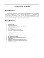
Introduction
RoMeo is an All-in-One microcontroller especially designed for robotics
application. Benefit from Arduino open source platform, it is supported by
thousands of open source codes, and can be easily expanded with most
Arduino Shields. The integrated 2 way DC motor driver and wireless socket
gives a much easier way to start your robotic project.
Specification
•
Atmega 168/328
•
14 Channels Digital I/O
•
6 PWM Channels (Pin11,Pin10,Pin9,Pin6,Pin5,Pin3)
•
8 Channels 10-bit Analog I/O
•
USB interface
•
Auto sensing/switching power input
•
ICSP header for direct program download
•
Serial Interface TTL Level
•
Support AREF
•
Support Male and Female Pin Header
•
Integrated sockets for APC220 RF Module and DF-Bluetooth Module
•
Five I2C Interface Pin Sets
•
Two way Motor Drive with 2A maximum current
•
7 key inputs
•
DC Supply:USB Powered or External 7V~12V DC。
•
DC Output:5V /3.3V DC and External Power Output
•
Dimension:90x80mm
DFRduino RoMeo Pinout
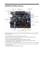
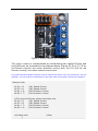
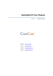
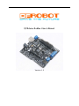
Figure 1 Romeo Pin Out
The picture above shows all of the I/O lines and Connectors on the Romeo,
which includes:
• One Regulated Motor Power Input Terminal (6v to12v)
• One Unregulated Servo Power Input Terminal (you supply regulated 4v to 7.2v)
• One Servo input power selection jumper
• One Serial Interface Module Header for APC220/Bluetooth Module
• Two DC Motor Terminals – Handles motor current draw up to 2A, each terminal
• One I2C/TWI Port – SDA, SCL, 5V, GND
• One Analog Port with 8 analog inputs – one input is tied internally to the supply voltage
• One General Purpose I/O Port with 13 I/O lines – 4,5,6,7 can be used to control motors
• One Reset Button
• Jumper bank to Enable/Disable Motor Control
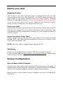
Before you start
Applying Power:
This is one of the most important steps in getting the Romeo up and
communicating with your host controller. You MUST make sure that you
apply power to the Power Terminal using the correct polarity. Reverse
Polarity will damage the Romeo. We are not responsible for such damage,
nor do we warranty against such damage. Make sure you take time to apply
power correctly. Otherwise, it could get costly for you!
Power from USB:
Simply plug USB cable, and the Romeo is able to work. Please notice that the
USB can only supply 500 mA current. It should be able to meet the most
requirements for LED lit application. However it is not enough to power DC
motors or servo.
Power from Motor Power Input:
Simply connect the ground wire from your supply to the screw terminal
labeled “GND”, and then connect the positive wire from your supply to the
screw terminal labeled “VIN”.
NOTE: Maximum supply voltage cannot exceed 14V DC.
Software:
RoMeo can be programmed by Arduino IDE 0014 and above version.
It can be downloaded at http://arduino.cc/en/Main/Software, Please select
“Arduino Nano” as the hardware.
Romeo Configuration
Servo Power Select Jumper:
As most servo draw more current than the USB power source can supply. A
separate servo power terminal is provided to power the servo individually
which can be Enable/Disable by the Servo Power Select Jumper.
When the Servo Power Select Jumper is applied, the servo is powered by
internal 5V.
When the Servo Power Select Jumper is not applied, the servo is powered by
external power source.
Motor Control Pin Jumper:
Applying the Motor Control Pin Jumpers will allocate Pin 5,6,7,8 for motor
control.
Removing the jumpers will release the above Pins.
Wireless Select Jumper:
Applying the Wireless Select Jumper will allow the Romeo communicate via
its wireless module such as APC220 and DF-Bluetooth module. If no wireless
module is plugged, this jumper does not make any difference.
Removing the jumper will disable wireless module and allows the sketch to
be uploaded.
Tutorial
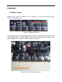
1. Button Press
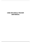
RoMeo has 7 build in buttons S1-S7 (Figure 2). S1-S5 use analog input,
S6,S7 use digital input.
Figure 2 Romeo Buttons
To enable S6 and S7, please apply the jumpers indicated in the red circle. S6
uses Digital Pin2, S7 uses Digital Pin3. Once these enable jumpers have
been applied, Pin 2 and 3 will be occupied (Figure 3).
Figure 3 Button Enable Jumpers
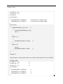
Sample code:
int ledPin = 13;
int key_s6 = 2;
int val=0;
void setup()
{
pinMode(ledPin, OUTPUT);
// Set Pin13 to output mode
pinMode(key_s6, INPUT);
// Set Pin12 to output mode
}
void loop()
{
if(digitalRead(key_s6)==0)
//
{
while(!digitalRead(key_s6));
val++;
}
if(val==1)
{
digitalWrite(ledPin, HIGH);
}
if(val==2)
{
val=0;
digitalWrite(ledPin, LOW);
}
//
//
}
Sample 2:
Code function: Press button S6, turn on LED, Press button S7, turn off LED.
Sample code:
int ledPin = 13;
int key_s6 = 2;
int key_s7 = 3;
void setup()
{
pinMode(ledPin, OUTPUT);
pinMode(key_s6, INPUT);
pinMode(key_s7, INPUT);
}
//
//
//
//
//
//
void loop()
{
if(digitalRead(key_s6)==0)
//
{
digitalWrite(ledPin, HIGH);
}
if(digitalRead(key_s7)==0)
//
{
digitalWrite(ledPin, LOW);
}
}
//
//
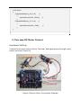
2. Two way DC Motor Control
Hardware Setting:
Connect four motor wires to Motor Terminal. And apply power through motor
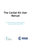
power terminal (Figure 4).
Figure 4 Romeo Motor Connection Diagram
Figure 5 Motor Control Pin Jumpers
The motor control is implemented by manipulating two digital IO pins and
two PWM pins. As illustrated in the diagram above (Figure 5), Pin 4,7 (7,8 for
old Romeo version) are motor direction control pins, Pin 5,6 (6,9 for old
Romeo version) are motor speed control pins.
For previous Romeo board, the pins used to control the motor is Pin 7,8 (Direction), Pin 6,9
(Speed). You can find the information at the right side of the Motor Control Pin Jumpers.
Sample Code:
int
int
int
int
E1 = 5;
E2 = 6;
M1 = 4;
M2 = 7;
//M1 Speed Control
//M2 Speed Control
//M1 Direction Control
//M1 Direction Control
///For previous Romeo, please use these pins.
int E1 = 6;
//M1 Speed Control
int E2 = 9;
//M2 Speed Control
int M1 = 7;
//M1 Direction Control
int M2 = 8;
//M1 Direction Control
void stop(void)
{
//Stop
digitalWrite(E1,LOW);
digitalWrite(E2,LOW);
void
void
void
void
}
advance(char a,char b)
{
analogWrite (E1,a);
digitalWrite(M1,HIGH);
analogWrite (E2,b);
digitalWrite(M2,HIGH);
}
back_off (char a,char b)
{
analogWrite (E1,a);
digitalWrite(M1,LOW);
analogWrite (E2,b);
digitalWrite(M2,LOW);
}
turn_L (char a,char b)
{
analogWrite (E1,a);
digitalWrite(M1,LOW);
analogWrite (E2,b);
digitalWrite(M2,HIGH);
}
turn_R (char a,char b)
{
analogWrite (E1,a);
digitalWrite(M1,HIGH);
analogWrite (E2,b);
digitalWrite(M2,LOW);
}
setup(void)
//Move forward
//PWM Speed Control
//Move backward
//Turn Left
//Turn Right
void
{
int i;
for(i=6;i<=9;i++)
pinMode(i, OUTPUT);
Serial.begin(19200);
//Set Baud Rate
}
void loop(void)
{
char val = Serial.read();
if(val!=-1)
{
switch(val)
{
case 'w'://Move Forward
advance (100,100);
break;
case 's'://Move Backward
back_off (100,100);
break;
case 'a'://Turn Left
turn_L (100,100);
break;
case 'd'://Turn Right
turn_R (100,100);
break;
}
delay(40);
//PWM Speed Control
}
else stop();
}
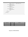
Release Date
Version
August 14, 2009
1.0
First Release
Comments
November 15, 2009
1.1
Modified Motor Control Pin for New Romeo
Copyright by DFRobot&YeRobot