1
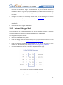
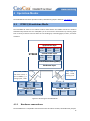
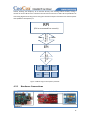
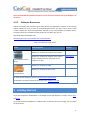
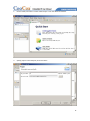
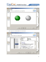
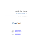
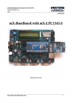
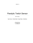
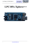
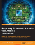
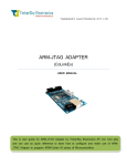
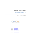
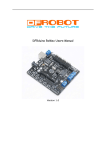
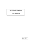
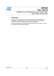
Embedded Pi User Manual Rev. 1.0 Website: www.coocox.org Forum: forum.coocox.org Techinal: [email protected] Market: [email protected] Release: 2013-04-25 Catalog Embedded Pi User Manual................................................................................................................ 0 1 Introduction .............................................................................................................................. 3 2 Key Features .............................................................................................................................. 4 3 Hardware Layout and Configuration ......................................................................................... 5 3.1 Block Diagram ............................................................................................................... 5 3.2 ESD Precautions ............................................................................................................ 8 3.3 MCU .............................................................................................................................. 9 3.4 Power ............................................................................................................................ 9 3.5 3.6 4 3.4.1 Power Supply..................................................................................................... 9 3.4.2 Power Pins ....................................................................................................... 10 Arduino Interfaces ....................................................................................................... 10 3.5.1 Power section .................................................................................................. 11 3.5.2 Analog section ................................................................................................. 11 3.5.3 ICSP/ SPI .......................................................................................................... 11 3.5.4 Digital section .................................................................................................. 12 Embedded Pi Extended Interfaces .............................................................................. 13 3.6.1 Custom Section................................................................................................ 13 3.6.2 Analog Section................................................................................................. 14 3.6.3 Digital Section.................................................................................................. 14 3.7 Raspberry Pi Connector............................................................................................... 15 3.8 Program the Embedded Pi .......................................................................................... 16 3.8.1 ISP mode ......................................................................................................... 16 3.8.2 External Debugger Mode ................................................................................ 17 3.9 Button.......................................................................................................................... 18 3.10 LED .............................................................................................................................. 18 3.11 System Clock Source.................................................................................................... 19 3.12 Jumper......................................................................................................................... 19 Operation Modes .................................................................................................................... 20 4.1 STM32/Standalone Mode ........................................................................................... 20 4.1.1 Hardware connections .................................................................................... 20 1 4.1.2 4.2 4.3 Software Resources ......................................................................................... 21 ST-Adapter Mode ........................................................................................................ 23 4.2.1 Hardware Connections .................................................................................... 24 4.2.2 Software Resources ......................................................................................... 25 Raspberry Pi Mode ...................................................................................................... 25 4.3.1 Hardware Connections .................................................................................... 26 4.3.2 Software Resources ......................................................................................... 27 5 Getting Started ........................................................................................................................ 27 6 Schematics .............................................................................................................................. 42 7 References ............................................................................................................................... 46 7.1 Cortex-M3 ................................................................................................................... 46 7.2 STM32 ......................................................................................................................... 46 7.3 CooCox ........................................................................................................................ 46 7.4 Raspberry Pi ................................................................................................................ 47 7.5 Arduino........................................................................................................................ 47 2 1 Introduction Figure 1-1 Embedded Pi board Embedded Pi is a triple-play platform for Raspberry Pi, Arduino and 32-bit embedded ARM. Blending all three communities together, Embedded Pi helps you to get the most out of each platform. The Embedded Pi is based on the STMicroelectronics STM32F103 MCU, and can operate as a bridge between Raspberry Pi and Arduino shields and in standalone mode as a Cortex-M3 evaluation board. Depending on the jumper placement on the Embedded Pi, you can select each of the three modes of operation: STM32/Standalone Mode The Embedded Pi works as an Arduino mother board where the STM32 controls the Arduino shields directly without the use of Raspberry Pi. More… ST-Adapter Mode The STM32 controls the Arduino shields, and the Raspberry Pi works as the GUI or command line console to send commands/data to and receive data from the STM32. More… Raspberry Pi Mode The Embedded Pi works as a hardware connection bridge between Raspberry Pi and Arduino shields, allowing the Raspberry Pi to interface directly with existing Arduino shields. More… 3 The figure below shows the hardware connections of different modes. Figure 1-2 Hardware connections of 3 operation modes 2 Key Features Provides Raspberry Pi with easy access to abundant Arduino shields. ‒ Compatible with both 5V and 3.3V Arduino shields, selectable with jumpers ‒ Hundreds of Arduino shields available on the market enhance the control capability of Raspberry Pi, e.g. to control Motor, sensors, etc. Brings 32-bit ARM MCU into the world of Arduino. ‒ 32-bit ARM Cortex-M3 STM32F103 MCU operating at 72MHz, with 128KB Flash, 20KB RAM, motor control, USB, and CAN ‒ Hundreds of Arduino shields available on the market with extremely portable drivers provided or to be shared by CooCox and CoFans ‒ A complete set of FREE CooCox tools for ARM development ‒ A common footprint next to Arduino footprint for connection with expansion daughter cards which will be developed by CooCox Raspberry Pi and the STM32 MCU can work independently or in conjunction with each other to control the Arduino shields or other accessories. 4 3 Hardware Layout and Configuration 3.1 Block Diagram Connect to RPI Board Embedded Pi On Board MCU Embedded Embedded Pi Pi MCU(stm32) MCU(stm32) IIC/SPI/UART/PWM/G PIO IIC/SPI/UART/PWM/A DC/GPIO/CAN SCL SDA SCL2 SDA2 AREF GND IO IO SCK MISO MOSI SS PWM IO SCK2 MISO2 MOSI2 SS2 CANTX CANRX IO PWM PWM IO PWM PWM- PWM+ PWM- PWM+ CTS2 IO RTS2 TX TX2 GPIO ADC CAN PWM UART SPI IIC Bus Switch & 3V3/5V Voltage-level translate RX RPI Connecter RX2 3 Power Source (auto Switch) USB Micro-B --------------------External DC USB RPI_5V Arduino-Compatible Embedded Pi Board DC-005 (7V – 16V) Embedded Pi MCU ISP(Program Interface) Arduino Standard Interfaces: 1SPI, 1I2C, 4PWM, 1 UART, 6 Analog Input Embedded Pi Extended Interfaces: 1 SPI, 1 I2C, 1 UART with Flow Ctrl, 2 Pairs PWM(+-),6 Analog Input, 1 CAN Embedded Pi Analog Input External Interface STM32 Debug Connecter Arduino Power Interface Arduino ADC Interface Figure 3-1 Hardware block diagram Besides the Arduino standard interfaces onboard, Embedded Pi has some additional SPI, IIC, UART interfaces, and some other extended interfaces like USB and CAN. Users can use the MCU onboard or a connected Raspberry Pi to control Arduino shields via the Arduino standard interfaces. The following sections give a detailed introduction of the operation modes and interfaces of Embedded Pi: 4 Operation Modes, 3.5 Arduino Interfaces, 3.6 Embedded Pi Extended Interfaces, and 3.7 Raspberry Pi Connector. Embedded Pi has 3 power sources from which the power supply is auto-selected – USB connection, an external DC power supply, or a Raspberry Pi. For more information, refer to 3.4 Power MCU. 5 Embedded Pi contains an ARM Cortex-M3 MCU STM32F103RBT6 which belongs to STM32 F1 series of mainstream MCUs. The STM32 F1 is a series of mainstream MCUs covering the needs of a large variety of applications in the industrial, medical and consumer markets. With this series of products, ST has pioneered the world of ARM® Cortex™-M microcontrollers and set a milestone in the history of embedded applications. High performance with first-class peripherals and low-power, low-voltage operation is paired with a high level of integration at accessible prices with a simple architecture and easy-to-use tools. The features of STM32F103RBT6 are listed below: 32-bit with ARM Cortex-M3 core running at up to 72MHz. 128KB Flash for programming, 20KB SRAM. Embedded Internal RC 8MHz and 32 kHz, Real-Time Clock. 16-bit Timers with Input Capture, Output Compare and PWM. 16-bit 6-ch Advanced Timer, 2 16-bit Watchdog Timers, SysTick Timer Rich communication interfaces: 2 SPI, 2 I2C, 3 USART USB 2.0 Full Speed Interface, CAN 2.0B Active 2 12-bit 16-ch A/D Converter 6 Arduino Bus Power Switch Raspberry Pi Interface Raspberry Pi Bus Enable STM32 Bus Enable Embedded Pi Extended Interface Debug Interface Arduino Interface Figure 3-2 Embedded Pi board layout 7 39 15 26 25 2 1 14 BOOT0 IOREF RESET 3V3 5V GND BOOT1 P O W E R RESET TX1 7 27 ID 40 ID ID 21 8 28 GND RX1 A N A L O G 10 9 NC VIN 12 11 3V3 GND 16 13 5 3 1 D I G I T A L ID NC GND ID ID AREF D I G I T A L 0 SPI 45 6 4 22 2 NOTE: Arduino Interface Embedded Pi Extended Interface Raspberry Pi Interface Figure 3-3 Pin IDs of the connectors 3.2 ESD Precautions Please note that the Embedded Pi board comes without any case/box and all components are exposed. Therefore, extra attention must be paid to ESD (electrostatic discharge) precautions. Please make sure there is no static interference when using the board. Appropriate ESD protections must be taken and wearing electrostatic equipment is recommended, such as wearing an anti-static wristband. ESD damage can range from subtle performance degradation to complete device failure. Precision integrated circuits may be more susceptible to damage because very small parametric changes could cause the device not to meet its published specifications. 8 3.3 MCU Embedded Pi contains an ARM Cortex-M3 MCU STM32F103RBT6 which belongs to STM32 F1 series of mainstream MCUs. The STM32 F1 is a series of mainstream MCUs covering the needs of a large variety of applications in the industrial, medical and consumer markets. With this series of products, ST has pioneered the world of ARM® Cortex™-M microcontrollers and set a milestone in the history of embedded applications. High performance with first-class peripherals and low-power, low-voltage operation is paired with a high level of integration at accessible prices with a simple architecture and easy-to-use tools. The features of STM32F103RBT6 are listed below: 32-bit with ARM Cortex-M3 core running at up to 72MHz. 128KB Flash for programming, 20KB SRAM. Embedded Internal RC 8MHz and 32 kHz, Real-Time Clock. 16-bit Timers with Input Capture, Output Compare and PWM. 16-bit 6-ch Advanced Timer, 2 16-bit Watchdog Timers, SysTick Timer Rich communication interfaces: 2 SPI, 2 I2C, 3 USART USB 2.0 Full Speed Interface, CAN 2.0B Active 2 12-bit 16-ch A/D Converter 3.4 Power 3.4.1 Power Supply Like the other Arduino mother boards, Embedded Pi can be powered via USB connection or with an external DC power supply. Besides, a connected Raspberry Pi can also supply power to it. The power supply is auto-selected from these 3 sources. External (non-USB) power can come either from an AC-to-DC adapter (wall-wart) or battery. The adapter can be connected by plugging a 2.1mm center-positive plug into the board's power jack. Leads from a battery or other DC power supply can be inserted in the GND and VIN pin headers of the POWER connector. Raspberry Pi can supply power to Embedded Pi by connecting P1 on Raspberry Pi with the Raspberry Pi connector (J5) on the Embedded Pi board via the 26-pin IDC cable in the package. Embedded Pi can operate on an external supply of 6 to 20 volts. If supplied with less than 7V, however, the 5V pin may supply less than five volts and the board may be unstable. If using more 9 than 12V, the voltage regulator may overheat and damage the board. The recommended range is 7 to 12 volts. Note: Embedded Pi has 3.3V and 5V outputs for power supply, selectable by JP1. You need to check and select which output to use every time when powering on the stacked Arduino shields. 3.4.2 Power Pins The power pins of Embedded Pi are fully compatible with those of Arduino and listed as below: VIN. VIN is a voltage input pin connected to the input of the voltage conversion chip onboard outputting 5V. As VIN is connected to the power jack with a diode between them, the voltage on the pin will be the same with the external power if any, ranging from 7 to 12V as recommended above. 5V. This is a 5V output pin with 2 voltage sources: 5V from USB connection, or an onboard voltage conversion chip if using a 7 to 12V external DC power supply. Note: Please do not input any external power directly to the pin, or your board can be damaged. 3V3. This is a 3.3V output pin extended from an onboard voltage conversion chip. GND. Ground pins. 3.5 Arduino Interfaces Embedded Pi has Arduino standard interfaces onboard, which provide easy access to controlling the Arduino shields. We have defined a digital ID for each signal as the name of the pin. 10 3.5.1 Power section Figure 3-4 Pin-outs of Arduino power interfaces (left side of the dotted line) 3.5.2 Analog section Arduino standard interfaces include 6 analog inputs, 2 of which have a multiple function for IIC communication. However, the 2 IIC pins have no analog input function on the Embedded Pi board. The specific IO mapping of the pins are as below: Table 3-1 IO mapping of Arduino analog interfaces Pin ID Arduino Function STM32 IO MAP MCU Peripheral Function 16 AIN PC0 PC0/ADC10 17 AIN PC1 PC1/ADC11 18 AIN PC2 PC2/ADC12 19 AIN PC3 PC3/ADC13 20 I2C.SDA PB7 PB7/I2C1_SDA/TIM4_CH2/USART1_RX 21 I2C.SCL PB6 PB6/I2C1_SCL/TIM4_CH1/USART1_TX 3.5.3 ICSP/ SPI Among Arduino standard interfaces, several digital IO and ICSP pins can also be used as SPI interface by multiplexing. Embedded Pi has full compliance with Arduino on these pins. The specific IO mapping of the ICSP pins are as below: Table 3-2 IO mapping of Arduino ICSP interface Arduino Pin Arduino Function STM32 IO MAP MCU Peripheral Function 11 ICSP.1 SPI.MISO PB14 ICSP.2 NC NC ICSP.3 SPI.SCK PB13 PB13/SPI2_SCK/USART3_CTS/TIM1 _CH1N ICSP.4 SPI.MOSI PB15 PB15/SPI2_MOSI/TIM1_CH3N ICSP.5 NC NC ICSP.6 GND NC 3.5.4 PB14/SPI2_MISO/USART3_RTS/TIM 1_CH2N Digital section Arduino standard interfaces include 16 digital IOs, which can also access 1 UART, 1 SPI, and 6 PWM signals by multiplexing. Embedded Pi has full compliance with Arduino on these pins. The specific IO mapping of the digital pins are as below: Table 3-3 IO mapping of Arduino digital interfaces Pin ID Arduino Function STM32F103 IO MAP MCU Peripheral Function 0 UART.RX PC11 PC11/USART3_RX 1 UART.TX PC10 PC10/USART3_TX 2 EXT.INT PC12 PC12/USART3_CK 3 EXT.INT / PWM PC6 PC6/TIM3_CH1 PC7 PC7/TIM3_CH2 4 5 PWM PC8 PC8/TIM3_CH3 6 PWM PC9 PC9/TIM3_CH4 7 PD2 PD2/TIM3_ETR 8 PA15 PA15/JTDI/TIM2_CH1_ETR/SPI1_NSS 9 PWM PA8 PA8/USART1_CK/TIM1_CH1/MCO 10 SPI.CS PB12 PB12/SPI2_NSS/I2C2_SMBAI/USART3_CK/ TIM1_BKIN 11 SPI.MOSI PB15 PB15/SPI2_MOSI/TIM1_CH3N 12 SPI.MISO PB14 PB14/SPI2_MISO/USART3_RTS/TIM1_CH2 N 13 SPI.CLK PB13 PB13/SPI2_SCK/USART3_CTS/TIM1_CH1N 12 AREF NC GND GND GND 14 I2C.SDA PB7 PB7/I2C1_SDA/TIM4_CH2/USART1_RX 15 I2C.SCL PB6 PB6/I2C1_SCL/TIM4_CH1/USART1_TX Note: To use D8 (Pin ID 8), you need to connect SJ1 to D8 with electric iron and solders. STM32-PA15 D8 JP2-TDI 3 3.6 2 1 SJ1 Embedded Pi Extended Interfaces The Embedded Pi extended interfaces beyond the Arduino standard interfaces provide stronger control ability on expansion modules. The expanded pins, from D22 to D45, including 1 SPI, 1 I2C, 1 UART with flow control, 2 pairs of PWM (+-), 6 analog inputs, and 1 CAN, are introduced by 3 sections below. 3.6.1 Custom Section This section is customized according to the features of MCU. It includes BOOT0 and BOOT1, the special pins of STM32F103RBT6, and 2 pins with multiple functions including PWM and UART. The UART function is for ISP download, which works together with BOOT0 and BOOT1. Figure 3-5 Embedded Pi extended custom interfaces (right side of the dotted line) Table 3-4 IO mapping of Embedded Pi extended custom interfaces Pin ID Embedded Pi Function STM32F103 IO Map MCU Peripheral Function 26 PWM.P PA9 PA9/USART1_TX/TIM1_CH2 28 PWM.P PA10 PA10/USART1_RX/TIM1_CH3 13 3.6.2 Analog Section Embedded Pi extended interfaces include 6 analog inputs, 4 of which shared the same MCU interface with the Arduino interfaces due to the limited analog inputs of STM32F103RBT6. The specific IO mapping of the analog pins are as below: Table 3-5 IO mapping of Embedded Pi extended analog interfaces Pin ID Embedded Pi Function STM32F103 IO Map MCU Peripheral Function 40 Analog PC0 PC0/ADC10 41 Analog PC1 PC1/ADC11 42 Analog PC2 PC2/ADC12 43 Analog PC3 PC3/ADC13 44 Analog PC4 PC4/ADC14 45 Analog PC5 PC5/ADC15 3.6.3 Digital Section Embedded Pi extended interfaces include 16 digital IOs, which can also access 1 UART with flow control, 2 pairs of differential PWM, 1 CAN, 1 SPI, and 1 IIC. The specific IO mapping of the digital pins are as below: Table 3-6 IO mapping of Embedded Pi extended digital interfaces Pin ID Embedded Pi Function STM32F103 IO Map MCU Peripheral Function 22 UART.RX PA3 PA3/USART2_RX/ADC3/TIM2_CH4 23 UART.TX PA2 PA2/USART2_TX/ADC2/TIM2_CH3 24 UART.RTS PA1 PA1/USART2_RTS/ADC1/TIM2_CH2 25 UART.CTS PA0 PA0-WKUP/USART2_CTS/ADC0/TIM2 _CH1_ETR 26 PWM.P PA9 PA9/USART1_TX/TIM1_CH2 27 PWM.N PB0 PB0/ADC8/TIM3_CH3/TIM1_CH2N 28 PWM.P PA10 PA10/USART1_RX/TIM1_CH3 29 PWM.N PB1 PB1/ADC9/TIM3_CH4/TIM1_CH3N 30 CAN.RX PB8 PB8/TIM4_CH3/I2C1_SCL/CANRX 31 CAN.TX PB9 PB9/TIM4_CH4/I2C1_SDA/CANTX 14 32 SPI.SS PA4 PA4/SPI1_NSS/USART2_CK/ADC4 33 SPI.MOSI PA7 PA7/SPI1_MOSI/ADC7/TIM3_CH2/TI M1_CH1N 34 SPI.MISO PA6 PA6/SPI1_MISO/ADC6/TIM3_CH1/TI M1_BKIN 35 SPI.SCK PA5 PA5/SPI1_SCK/ADC5 36 PC13 PC13/ANT1_TAMP 37 PB5 PB5/I2C1_SMBAI/TIM3_CH2/SPI1_M OSI 38 I2C.SDA PB11 PB11/I2C2_SDA/USART3_RX/TIM2_C H4 39 I2C.SCL PB10 PB10/I2C2_SCL/USART3_TX/TIM2_C H3 3.7 Raspberry Pi Connector Raspberry Pi Connector (JP5) includes 17 digital IOs, which also have the function of IIC, SPI, or UART. As the Arduino standard interfaces include only 16 digital IOs, pin 26 of the Raspberry Pi is ignored on Embedded Pi. Below is the IO remapping of Raspberry Pi interfaces on Embedded Pi board. Table 3-7 IO remapping of Raspberry Pi interfaces Note: Dn (n=1.2.3 …) stands for Digital Pin x. Raspberry-Pi Interface Pin ID Raspberry-Pi Interface Function Embedded Pi Pin remap 1 3.3V Power 3.3V Power 2 5V Power 5V Power 3 GPIO0/SDA D14 4 5V Power NC 5 GPIO1/SCL D15 6 GND GND 7 GPIO4/GPCLK0 D9 8 GPIO14/TXD D1 9 GND NC 15 10 GPIO15/RXD D0 11 GPIO17 D2 12 GPIO18/PCM_CLK D3 13 GPIO21/PCM_DOUT D4 14 GND NC 15 GPIO22 D5 16 GPIO23 D6 17 3.3V Power NC 18 GPIO24 D7 19 GPIO10/MOSI D11 20 GND NC 21 GPIO9/MISO D12 22 GPIO25 D8 23 GPIO11/SCKL D13 24 GPIO8/CE0 D10 25 GND NC 26 GPIO7/CE1 NC 3.8 Program the Embedded Pi 3.8.1 ISP mode In ISP mode, a PC programs the MCU onboard via the serial port (JP7-TX1 and JP7-RX1), refer to section 3.6.1. To use this mode, you need to set BOOT0 to 1 (high level), and BOOT1 to 0 (low level) – which has been done on hardware. In this case, you only need to press the BOOT0 button to enter this mode when Embedded Pi is powered on. The next steps are as below: 1) Install the ISP tool for Embedded Pi on your PC or Raspberry Pi. There are many ISP tools for PC, and ST has provided a version for Windows system only. For details, please refer to http://www.st.com/internet/com/TECHNICAL_RESOURCES/TECHNICAL_LITERATURE/USER_ MANUAL/CD00171488.pdf. Raspberry Pi uses the Linux system, where no ISP tools are available yet, and need to be developed. 2) Disconnect Embedded Pi from power. 16 3) Connect the ISP interface on Embedded Pi with your PC (or Raspberry Pi) according to the instruction of the ISP tool. Figure 3-14 below shows the pins of the ISP interface on Embedded Pi. When using a PC to program Embedded Pi, an RS232 voltage conversion chip is needed between to convert the TTL voltage level of Embedded Pi to the RS232 voltage level of PC. 4) Configure JP1 to select the bus voltage between 3.3V and 5V according to the Arduino shields in use. For configuration information of JP1, refer to 3.12 Jumper. 5) Power on Embedded Pi, the power indicator LED will be lighted. Press BOOT0 and hold it there, and press RESET button for 1 second, then release BOOT0, the Embedded Pi will enter the ISP mode. 6) Launch the ISP tool to program Embedded Pi. 3.8.2 External Debugger Mode Since Embedded Pi has no debugger onboard, an external JTAG/SWD debugger is needed to program Embedded Pi in the External Debugger Mode, like J-Link and CoLinkEx. The configuration steps are as below: 1) Disconnect Embedded Pi from power. 2) Install the debugger driver on PC. You can ship this step if you have installed one. To install the driver of CoLinkEx, refer to http://www.coocox.org/Colinkex.htm. 3) Install the integrated development environment on PC. You can ship this step if you have installed one. To install CoIDE, refer to http://www.coocox.org/CooCox_CoIDE.htm. 4) Connect Embedded Pi to the PC via the 10-Pin JTAG/SWD interface (JP2). Figure 3-6 Pin-outs of the 10-Pin JTAG/SWD interface 5) Power on Embedded Pi, the power indicator LED will be lighted. 6) Start download and debug your program. 17 Note: SWD debuggers are supported by default. To use a JTAG debugger, you need to connect SJ1 with JTDI first with electronic iron and solders. STM32-PA15 D8 JP2-TDI 3 3.9 2 1 SJ1 Button Table 3-8 Function of buttons on Embedded Pi Button ID Name Function 1 RESET Reset the Embedded Pi or the Arduino shields in use 2 BOOT0 Select Boot Mode Remark Reference: 1) STM32 Flash Programming Manual (PM0042) 2) Chapter 3.8.1 3.10 LED Table 3-9 Function of LEDs on Embedded Pi LED ID Function Note 1 User LED 1) LED Pin – PB13 2) LED Control method PB13 Pin high LED ON (Green) PB13 Pin low LED OFF 2 Indicate Power Status Power ON LED ON (Green) Power OFF LED OFF 18 3.11 System Clock Source Table 3-10 System Clock Source Function of Embedded Pi Clock Source ID Crystal Frequency Function 1 8MHz System main clock source 2 32.768KHz RTC input clock source 3.12 Jumper Table 3-11 Function of Embedded Pi Jumpers Jumper ID Function Description 1 Output 3V3 JP1 Bus Power Selection 1 Output 5V JP3 Raspberry Pi Bus Enablement To configure operation mode. JP4 STM32 Bus Enablement To configure operation mode. Table 3-12 Operation mode configuration Operation Mode Jumpers Configuration STM32/Standalone Mode ST-Adapter Mode Raspberry Pi Mode 19 4 Operation Modes The Embedded Pi has three operation modes, selectable by jumpers. Refer to 3.12 Jumper. 4.1 STM32/Standalone Mode The Embedded Pi works as an Arduino mother board where the STM32 controls the Arduino shields directly without the use of Raspberry Pi. It can sense the environment by receiving input from a variety of sensors and can affect its surroundings by controlling lights, motors, and other actuators. Application layer LCD Driver Motor Driver Sensor Driver Shield Driver layer STM32 Key Driver WiFi,Eth Driver ... CoX STM32 library (HAL) in te r 1 SPI, 1 I2C, 1 UART te nd ed with flow control, 2 1 SPI, 1 I2C, 4 PWM, 1 UART, 6 analog inputs EP I analog inputs, 1 CAN ex pairs of PWM (+-), 6 rd da an st ces o in rfa du te Ar in fa ce s Hardware layer LCD Motor Senser LCD CooCox Shields Key Network Motor Senser Arduino Shields ... Key Network ... Figure 4-1 Block diagram of STM32 Mode 4.1.1 Hardware connections The Embedded Pi is compatible with both 5V and 3.3V Arduino shields, selectable with jumpers. 20 Arduino shields can plug pin-to-pin onto Embedded Pi via the Arduino footprint (I/O headers rev3) / Arduino standard interfaces. Next to the Arduino standard interfaces, the Embedded Pi also has on board the extended interfaces as SPI, UART, I2C, PWM and CAN, making up another set of common footprint for connection with expansion daughter cards which will be developed by CooCox. The Embedded Pi allows the SWD/JTAG debugging via the SWD/JTAG port, and programming via the ISP interface as well. It can be powered by auto-selection via USB connection, with an external DC power supply, or with the connected Raspberry Pi. Figure 4-2 Hardware connections of STM32 Mode 4.1.2 Software Resources A quick & easy embedded project can be built in C using CooCox development tools from Embest, a FREE and easy-to-use ARM development tool environment working in Windows XP SP3/Windows Vista/Windows 7 system for Cortex-M MCU with flash programming & debugging capability (CoIDE, CoFlash, CoLinkEx etc), along with the integrated abundant reusable code shared by CooCox team and CoFans. Click here to get started with the Embedded Pi and CoIDE. You can also view the demo video on: http://www.coocox.org/blog/?p=172 The table below shows the currently available Arduino shield drivers based on CoX, which are fully compatible with the Embedded Pi, and can be directly selected and added to user’s project within CoIDE. Application examples are provided along with the drivers for direct use or reference. Table 4-1 Arduino shield drivers based on CoX 21 Arduino shield Driver link State Product page DFRobot LCD Shield Done http://shieldlist.org/dfrobot/lcd Adafruit Motor Shield Done http://shieldlist.org/adafruit/motor Sensor_Shield Done http://store.arduino.cc/ww/index.php? main_page=product_info&cPath=16&pr oducts_id=89 LCD4884 Shield Done http://shieldlist.org/dfrobot/lcd4884 DM163 Matrix Shield Done http://shieldlist.org/itead-studio/colors EB-365 GPS Shield Done http://store.iteadstudio.com/index.php? main_page=product_info&cPath=18&pr oducts_id=500 Arduino GPRS Shield Under Developm ent http://shieldlist.org/seeedstudio/gprs Done http://uk.farnell.com/arduino/a000058/ board-wifi-shield-w-intg-antenna/dp/22 12785 Done http://uk.farnell.com/arduino/a000079/l 298-motor-control-arduino-shield/dp/20 75346 Arduino WiFi Shield Arduino Motor Shield For latest shared Arduino shield drivers, visit http://www.coocox.org/driver/shield-mc9.html, or click “Refresh” button on the top right corner of the Repository view in CoIDE, as shown in the figure below. Click the “Upload” button next to “Refresh” to share your Arduino shield drivers with others by just 4 steps. 22 Figure 4-3 Arduino shield drivers list & “Refresh” button 4.2 ST-Adapter Mode Preparation: A firmware to control the Arduino shields and communicate with the Raspberry Pi should be programmed to the STM32 before hand; it can be generated from the project built in CoIDE, and be programmed with CoIDE, CoFlash, or ISP tool. The source code to control the Arduino shields are the same with those in the STM32/Standalone Mode, while the Protocol Decode Layer code components (as shown in Figure 6) for communication with the Raspberry Pi will be provided in CoIDE and this page. The STM32 controls the Arduino shields, and the Raspberry Pi works as the GUI or command line console to send commands/data to and receive data from the STM32. This is an advanced mode which extends and strengthens the automation control capability of the Raspberry Pi, taking the advantage of STM32F103 NVIC (Nested Vectored Interrupt Controller), GPIOs, and more peripherals like ADC and PWM. 23 RPI LCD Driver (I2C/SPI/UART) CMD RPI connector (GUI or command line console) DATA Motor Driver Sensor Driver Shield Driver layer Key Driver STM32 WiFi,Eth Driver ... Protocol Decode layer CoX STM32 library (HAL) in te r 1 SPI, 1 I2C, 1 UART te nd ed with flow control, 2 LCD Motor Senser LCD CooCox Shields Key 1 SPI, 1 I2C, 4 PWM, 1 UART, 6 analog inputs EP I analog inputs, 1 CAN ex pairs of PWM (+-), 6 rd da an st ces o in rfa du te Ar in fa ce s Hardware layer Network Motor Senser Arduino Shields ... Key Network ... Figure 4-4 Block diagram of ST-Adapter Mode 4.2.1 Hardware Connections The Raspberry Pi communicates with STM32 via the SPI/I2C/UART channels of the Raspberry Pi connector, which are used as multiplex functions of the digital IOs. The Embedded Pi can be powered with the connected Raspberry Pi. 24 Figure 4-5 Hardware connections of ST-Adapter Mode 4.2.2 Software Resources The C++ source code to send commands/data to or receive data from the STM32, running in the Raspberry Pi ARM11 SoC @700MHz, Debian “wheezy” OS with 1080P resolution, are provided in CooCox Blog, bundling with the STM32 firmware and source code. To develop applications in this mode using the Arduino shields supported by CoIDE, users just need to develop/replace the Protocol Decode Layer code and the C++ code to run in the Raspberry Pi Debian system, following the instruction manuals which will be offered by CooCox team later. Table 4-2 ST-Adapter mode demos Shield Demo description Blog link A demo for ultrasonic distance measuring, can detect the geomagnetic field and measure the voltage of sliding rheostat Ultrasonic Demo AD Demo Arduino Motor Shield Raspberry Pi can control motor, LED, or GPIO of STM32 with commands by invoking command parameters already defined TinkerKit Shield For more demos and divers, please visit www.coocox.org/epi.html. The ST-Adapter mode’s document can be get from: St-adapter_en.pdf 4.3 Raspberry Pi Mode The Embedded Pi works as a hardware connection bridge between Raspberry Pi and Arduino 25 shields, allowing the Raspberry Pi to interface directly with existing Arduino shields, having a number of sensors & control to interact with external environment. It offers all the possibilities of connecting digital and analog sensors using the common footprint of Arduino but with the power and capabilities of Raspberry Pi. RPI (I2C/SPI/UART) CMD RPI connector (GUI or command line console) DATA Arduino standard interfaces EPI LCD Motor Senser Arduino Shields Key Network ... Figure 4-6 Block diagram of Raspberry Pi Mode 4.3.1 Hardware Connections 26 Figure 4-7 Hardware connections of Raspberry Pi Mode Note: The Embedded Pi Extended Interfaces are not connected with the pins of the Raspberry Pi Connector. 4.3.2 Software Resources Arduino community has provided a great many drivers and application examples of the existing Arduino shields for Linux, as well as corresponding document. The open source library called “arduPi” enables the drivers and application examples to run in the Raspberry Pi Debian system, including most drivers of Arduino shield peripherals, like GPIO, I2C, SPI, etc. Download arduPi for Raspberry Pi: Modified arduPi library compatible with the Embedded Pi Table 4-3 Raspberry Pi mode demos Shield Demo description Blog link Raspberry Pi controls the rotation of the motors Arduino Motor-Control Shield Raspberry Pi controls the rotation of the motors, and the rotation direction and speed can be configured via GUI. Ras-Pi Demo Raspberry Pi controls the LEDs Raspberry Pi controls the LCD via I2C TinkerKit Shield For more demos and divers, please visit www.coocox.org/epi.html. The Raspberry Pi mode’s document can be get from: raspberry_en.pdf 5 Getting Started To get started with the Embedded Pi in ST-Adapter mode and Raspberry Pi mode, refer to 4.2.2 and 4.3.2. To get started with Embedded Pi in STM32 mode, an Arduino shield, and CoIDE, you can follow the steps below: 27 1. Launch CoIDE, and select “Create a New Project” from the Welcome window. 2. Specify project name and path, and click “Next”. 28 3. Stay the cursor on “Chip” to create the project based on the target chip, and click “Next”. 4. Select target chip “STM32F103RB” from the chip list. 29 5. After clicking “Finish”, CoIDE will create a project containing a main.c file for you, and show the Repository window which contains all code components of STM32F103RB. 30 6. Select the driver component of your Arduino shield from the “Drivers” tab, e.g. select Shield -> DM163 Dot Matrix, associated components (xGPIO in this case) will be automatically selected, and CoIDE will add the source code of the selected components to your project. 31 7. Select View -> Help to open the Help window and view the related information of a selected component. 32 8. In the “Peripherals” tab, select CoX.Embedded_PI.Config component to add the interface configuration files to the project. 33 9. The Components view shows all selected components and the number of examples for each component. Click DM163 Dot Matrix component and its Example window will popup. Click “view” to view the content of the example file. 34 10. Click “add” to add the example file to your project, and click “Yes” to confirm adding. CoIDE will add the DotMatrix_example.c file to the project, and the DotMatrix_example function to the main function. 35 However, the DotMatrix_example.c file has 2 unsolved inclusions – xcore.h and xsysctl.h. 11. Select components xCORE and xSysCtl from the “Peripherals” tab. 36 12. Click the “Build” button or press F7 to compile and link the program. 13. Click the “Configuration” button to open the Configuration window. 37 14. Select the debug adapter you use in the “Debugger” tab, and close the Configuration window to save your configurations. 15. Click the “Download” button to download code to flash. 38 16. To start debugging, click on the Debug icon or press Ctrl+F5. 17. If debugging is launched successfully, CoIDE will enter the debug mode. 39 18. Other debug windows can be added by simply selecting them from the View menu. 19. Use the debug functions like single stepping via the tool bar or debug menu. 40 20. Set breakpoints in the C code window or the Disassembly window. 41 6 Schematics 42 43 44 45 7 References 7.1 1. Cortex-M3 ARM documentation set for the ARM Cortex-M3 CPU processor cores http://infocenter.arm.com/help/index.jsp?topic=/com.arm.doc.subset.cortexm.m3/index.html 2. ARMv7-M Architecture Reference Manual http://infocenter.arm.com/help/topic/com.arm.doc.ddi0403c/index.html 7.2 1. STM32 STM32F103RBT6 Datasheet http://www.st.com/internet/com/TECHNICAL_RESOURCES/TECHNICAL_LITERATURE/DATASHEET/ CD00161566.pdf 2. STM32F10xxx Flash memory microcontrollers http://www.st.com/internet/com/TECHNICAL_RESOURCES/TECHNICAL_LITERATURE/PROGRAM MING_MANUAL/CD00283419.pdf 3. STM32F10xxx/20xxx/21xxx/L1xxxx Cortex-M3 programming manual http://www.st.com/internet/com/TECHNICAL_RESOURCES/TECHNICAL_LITERATURE/PROGRAM MING_MANUAL/CD00228163.pdf 4. RM0008: STM32F10xx Reference Manual http://www.st.com/internet/com/TECHNICAL_RESOURCES/TECHNICAL_LITERATURE/REFERENCE _MANUAL/CD00171190.pdf 5. More resources http://www.st.com/internet/mcu/product/164487.jsp 7.3 1. CooCox CooCox Embedded Pi Page http://www.coocox.org/epi.html 2. CooCox Forum http://www.coocox.org/Forum/index.php 3. CooCox CoX http://www.coocox.org/COX.html 46 4. CooCox CoIDE http://www.coocox.org/CooCox_CoIDE.htm 7.4 1. Raspberry Pi Raspberry Pi HomePage http://www.raspberrypi.org/ 2. Raspberry Pi order links http://downloads.element14.com/raspberryPi1.html 3. FAQs http://www.raspberrypi.org/faqs 4. Element14 Raspberry-Pi community http://www.element14.com/community/groups/raspberry-pi 7.5 1. Arduino Arduino HomePage http://www.arduino.cc/ 2. Arduino Community http://arduino.org/ 3. Arduino Shields http://www.shieldlist.org/ 47