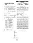
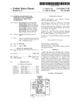
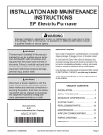
1
US007327354B2
(12) United States Patent
(10) Patent N0.:
(45) Date of Patent:
Dotson
(54)
LOW POWER DISSIPATION TOUCH PLANE
INTERFACE CIRCUIT
(73) Assignee: Rockwell Automation Technologies,
Inc., May?eld Heights, OH (US)
Notice:
Feb. 5, 2008
OTHER PUBLICATIONS
Prentice Hall’s Illustrated Dictionary of Computing, 2nd Ed., 1985,
(75) Inventor: Gary Dan Dotson, Muskego, WI (US)
(*)
US 7,327,354 B2
p. 59.
(Continued)
Primary ExamineriHenry N Tran
(74) Attorney, Agent, or FirmiHimanshu S. Amin;
Subject to any disclaimer, the term of this
patent is extended or adjusted under 35
Alexander M. GerasimoW
U.S.C. 154(b) by 512 days.
(57)
ABSTRACT
A method of determining a type of touch plane operator
(21) Appl. No.: 10/832,668
input device comprises sensing the impedance across ?rst
(22) Filed:
Apr. 27, 2004
(65)
and second terminals of a touch plane operator input device
to distinguish the touch plane operator input device as being
Prior Publication Data
US 2004/0196269 A1
one of at least tWo different types of touch plane operator
input devices. A method of processing an input from a touch
Oct. 7, 2004
plane operator input device comprises determining a ?rst
location of a ?rst touch on the touch plane operator input
Related US. Application Data
device; determining a second location of a second touch on
(63)
Continuation of application No. 09/677,103, ?led on
Sep. 29, 2000, noW Pat. No. 6,753,853.
the touch plane operator input device; comparing the ?rst
(51)
Int. Cl.
G09G 5/00
(2006.01)
difference between the ?rst and second locations; and deter
mining Whether the indication of the amount of difference
exceeds a predetermined amount. These steps are performed
(52)
US. Cl. .............. ..
345/174; 178/1801; 178/1802;
by discrete logic circuitry that provides an event noti?cation
178/2001
to a microprocessor When the indication of the amount of
Field of Classi?cation Search ...... .. 345/173*179;
difference exceeds the predetermined amount. An interface
circuit for a touch plane operator input device comprises a
digital signal processor that includes a data processing path
along Which data from a touch plane operator input device
(58)
178/18.01*18.07, 190141904, 200142004
See application ?le for complete search history.
(56)
References Cited
U.S. PATENT DOCUMENTS
4,413,314 A
11/1983 Slater et al.
(Continued)
and second locations to obtain an indication of an amount of
passes While being processed by the digital signal processor.
The interface circuit is capable of processing data from ?rst
and second different types of touch plane operator input
devices. The data path is a common data processing path that
is the same for input data for both of the ?rst and second
types of touch plane operator input devices.
FOREIGN PATENT DOCUMENTS
WO
WO98/49650
20 Claims, 11 Drawing Sheets
11/1998
TUUClLFREsS
US 7,327,354 B2
Page 2
U.S. PATENT DOCUMENTS
6,292,181 B1
9/2001 Banerjee et al.
9/2002 Chambers et al.
8/2003 Dotson et al.
6/2004 Dotson ..................... .. 345/173
7/2004 Dotson ..................... .. 345/173
4908620 A
3/1990 Fujisawa
6,445,383 B1
6,611,257 B1
4942514 A
5,014,051 A
7/1990 Miyagaki er 915/1991 LiPPmaIm er 91-
6,753,853 Bl*
6,765,558 Bl*
5,053,758 A
10/1991 Cornett et al.
5,376,947 A
12/1994 Kuroda
5,867,665 A
5,880,411 A
2/1999 Butman et al.
3/ 1999 Gillespie et al.
OTHER PUBLICATIONS
The New IEEE Standard Dictionary of Electrical and Electronics
5,956,020 A
5,995,084 A *
9/1999 D’Amico et al. ......... .. 345/173
11/1999 Chan et al. ............... .. 345/173
Terms, 5th Ed., 1983, p. 1051.
Setup and User Manual Hampshire TSHARC-8 Touch Screen
6,037,930
6,088,628
6,091,031
6,163,313
3/2000
7/2000
7/2000
12/2000
5/2001
Controller Board (Revision 1.6) pp. 3 & 7.
“MDS 7121 Touch Screen Controller Data Sheet” Printed Nov. 16,
2000 (Revised Oct. 8, 1999). pp. 1-16.
A
A
A
A
6,229,472 B1
Wolfe 6t 81.
Watanabe et a1~
Lee er a1
Aroyan et al.
Nidhida
* cited by examiner
U.S. Patent
Feb. 5, 2008
Sheet 1 0f 11
US 7,327,354 B2
32
Y+
X-
_L_______
Y+
X.
2?
/
14
5y, l
T
q
'1;
$Y
3X_
:
a:
.
43
as
.
1
‘u
a!
.
41
2°
5
L16
s
z
/ 2
2
"0
20
:
C-____‘_'l 12
~';
2
‘
"_ 12
T-k “
3°
30
“Prior Art“
"Prior Art"
F I G. 1A
FIG. 1 B
V+
V+
24-!2Y4;
Z51.
14+
5a
a:
56
‘W is‘
as
J
r
a:
I“
‘v T
/5‘
62
\
wiper
so
,/
J
wine: ‘on
w
87/
/
as
51
"Prior Art"
FIG. 1C
"Prior Al"?I
FIG. 1D
‘ 6Q
U.S. Patent
Feb. 5, 2008
Sheet 4 0f 11
Touch screen
connected?
152
8-wire touch
screen
connected?
4-wire touch
screen
connected‘?
5-wire touch screen
connected
Touch screen
pressed?
FIG. 4A
US 7,327,354 B2
U.S. Patent
Feb. 5, 2008
Sheet 5 0f 11
172
Touch screen
connected?
174
180
176
4-wire or 8-wire
4-wire
touch screen
touch screen
connected?
connected?
5-wire or 7-wire
touch screen
Y
connected
182
5-wire touch
screen
connected?
7-wire touch screen
connected
ouch screen
operating
properiy?
Touch screen
FIG. 4B
pressed?
US 7,327,354 B2
U.S. Patent
Feb. 5, 2008
Sheet 6 0f 11
US 7,327,354 B2
.mEUm.GEOm
.OE(mmm
U.S. Patent
Feb. 5, 2008
wmFomouca-l mass
Sheet 7 0f 11
US 7,327,354 B2
m
224
SCAN Y-AXIS
(TAKE 4, 8, 18. OR 32
SAMPLES STORING
SCAN X-AXIS
(TN<E4.a.1a.oRa2
smpms sromuem
MIN. AND AVERAGE)
2°‘
MAX, MINrAND AVERAGE)
ABS (MAX-MIN
DEVIATIG‘J?
X INT
PENDING?
210
ABS (x-xusn
XMIN?
212
SETXINT PENDING PA
XLAST B X
ABS
LESS THAN
N
m?
216
214
Y
SET X INT PENDING
XLASTaX
SET Y INT PENDNG
WBY
H6. 6
U.S. Patent
Feb. 5, 2008
Sheet 9 0f 11
US 7,327,354 B2
.OEOw
Ow
W
mw
.QE<w
U.S. Patent
Feb. 5, 2008
Sheet 10 0f 11
mm
US 7,327,354 B2
2 77
mm c
2%?
FIG. 9
3‘?
‘\
30o
4
30‘!
/
+
305
J 302
308/
FIG. 10
'
- l/O
U.S. Patent
Feb. 5,2008
1/
US 7,327,354 B2
Sheet 11 01 11
14/0
/ H00
@102
/
V0
V0
1
1
FIG. 11
V0
1
US 7,327,354 B2
1
2
LOW POWER DISSIPATION TOUCH PLANE
INTERFACE CIRCUIT
touch screens tend to be different because voltage feedback
provisions are made to compensate for the effects of resis
tance and temperature drift due to the larger screen siZe.
Additionally, even Within the feedback/nonfeedback catego
ries of touch screens, variations exist. As a result, it has been
dif?cult to provide a system-on-chip that is usable in a Wide
CROSS-REFERENCE TO RELATED
APPLICATIONS
This application is a continuation of US. application Ser.
No. 09/677,103 ?led Sep. 29, 2000 now US. Pat. No.
6,753,853 and entitled “LOW POWER DISSIPATION
TOUCH PLANE INTERFACE CIRCUIT,” the entirety of
variety of touch screen applications because different touch
screen applications tend to use different types of touch
screens and different types of touch screens have different
interface characteristics.
FIGS. 1A-1D beloW shoW four different types of com
Which is incorporated herein by reference.
monly employed analog resistive touch screens. In general,
BACKGROUND OF THE INVENTION
most analog resistive touch screens comprise front and back
resistive layers (often formed of indium tin oxide) that are
pressed together When an operator touch is received. The
1. Field of the Invention
This invention relates to interface circuits for touch
screens. This invention also relates to methods of processing
inputs from touch screens. This invention also relates to
integrated circuits that include interfaces for touch screens.
2. Description of Related Art
Touch plane operator input devices, such as touch screens
and touch pads, are knoWn. Typically, a touch plane operator
input device provides a generally planar surface that is
sensitive to the touch of an operator and is operative to
provide one or more output signals indicative of the location
operator touch causes the tWo layers to establish an electrical
contact at a particular location on each layer. Therefore, by
applying a voltage to one layer and reading the voltage
20
characteristics of each layer.
25
of the touch on the plane. The output signals may be based
either on the raW data from a touch screen sensor system, or
35
as Well as industrial applications such as operator interfaces
40
that connects to a Y+ terminal 28 of the touch screen, and a
Y- bus bar 30 that connects to a Y- terminal 32 of the touch
screen. The touch screen is scanned in the X-direction by
applying a voltage across the X+ and X- bus bars 16 and 20,
and then sensing the voltage that appears at one or both of
the Y+ and Y- terminals 28 and 32. Assuming negligible
current ?oW through the Y+ and Y- terminals, the voltage at
the Y+ and Y- terminals 28 and 32 should be approximately
the same and is determined by the X-coordinate of the point
of electrical contact betWeen the X-axis and Y-axis layers 12
and 14, that is, by the X-coordinate of the touch. By
comparing the voltage to values determined during calibra
45
on laptop computers to alloW operator control of a mouse
pointer. Numerous other applications also exist.
tion, the X-coordinate of the touch can be determined. The
Y-coordinate of the touch is then determined in the same
manner, except that a voltage is applied across the Y+ and
Y- bus bars 26 and 30, and the resultant voltage that appears
For convenience, the discussion Will noW focus on touch
screens, it being understood that the discussion is equally
applicable to touch pads and other touch plane operator
terminal 18 of the touch screen, and an X- bus bar 20 that
connects to an X- terminal 22 of the touch screen. Similarly,
the Y-axis resistive layer further includes a Y+ bus bar 26
the operator. Touch screens have been put to use in a Wide
in industrial control systems. In some applications, the
operator touch is made by a stylus or other device held by
the operator. In other applications, the operator touches the
screen directly.
Touch pads are similar in operation to touch screens,
except that they are not used in connection With a display
device. Touch pads are often placed adjacent the space bar
screen comprises an X-axis resistive layer 12 and a Y-axis
further includes an X+ bus bar 16 that connects to an X+
30
device that include a touch plane operator input device.
Touch screens are therefore capable not only of displaying
information to an operator, but also of receiving inputs from
variety of applications. Such applications include consumer
applications such as personal digital assistants (PDAs),
digital audio playback systems, internet devices, and so on,
For example, FIG. 1A is a schematic diagram of a 4-Wire
analog resistive touch screen. As shoWn therein, the touch
resistive layer 14. The resistance of the layers 12 and 14 is
shoWn schematically as four resistors. The X-axis layer 12
may be based on processed data that provides X-Y coordi
nate information of the touch.
Touch screens are an enhanced type of computer display
established by electrical contact on the other layer, the
location of the touch can be determined based on the knoWn
50
input devices. In many touch screen systems, a computer
system is implemented using “system-on-hip” integrated
at one or both of the X+ and X- terminals 18 and 22 is
sensed. Of course, With all touch screens, X and Y axis
de?nitions are arbitrary and different de?nitions can be
coordinated With program code to determine screen position.
circuits. In a single chip, these integrated circuits provide
FIG. 1B is a schematic diagram of an 8-Wire analog
many of the functions that used to be spread among many
integrated circuits. For example, in addition to the main
microprocessor, it is not uncommon to have other circuits
such as specialiZed serial interfaces, UARTs, memory con
resistive touch screen. The 8-Wire touch screen is the same
55
as the 4-Wire touch screen, except that four additional sX+,
sX-, sY+ and sY- feedback terminals 40-43 are provided.
Typically, both 4-Wire touch screens and 8-Wire touch
trollers, DMA controllers, Ethernet interfaces, display inter
screens use an analog-to-digital converter to sense the
faces, USB (universal serial bus) interfaces, and so on, as
voltages that appear at the X+ and Y+ terminals. In the case
of a 4-Wire touch screen, the reference voltage inputs to the
analog-to-digital converter are connected directly to the
same positive and ground terminals of a poWer supply that
also applies voltages to the touch screen. In the case of an
8-Wire touch screen, the reference voltage inputs are con
nected to sX+ and sX- terminals 40 and 42 of the X+ and
X- bus bars or to sY+ and sY- terminals 41 and 43 of the
Well as a touch screen interface used to acquire data from a 60
touch screen.
Aproblem that has been encountered With system-on-chip
integrated circuits adapted for use With touch screens is that
there are many different types of touch screens. For example,
some touch screens are relatively small (e. g., three inches or
less) Whereas other touch screens are much larger (e.g.,
tWenty inches or more). The interface characteristics of large
65
Y+ and Y- bus bars, respectively. The sX+, sX-, sY+ and
US 7,327,354 B2
3
4
sY- terminals 40-43 are used for voltage feedback to
eliminate the effects of resistance and temperature drift in
SUMMARY OF THE INVENTION
the circuit components.
According to one aspect of the invention, the invention
FIG. 1C is a schematic diagram of a 5-Wire analog
resistive touch screen. The 5-Wire analog resistive touch
screen includes a resistive layer 52 and a Wiper layer 54. The
relates to a method of determining a type of a touch plane
operator input device comprising sensing the impedance
resistive layer includes V+, V—, Z+/—, and Z—/+ terminals
across ?rst and second terminals of a touch plane operator
input device to distinguish the touch screen as being one of
56-59 at the four opposing corners of the touch screen. A
at least tWo different types of touch plane operator input
constant voltage is applied to the V+ and V- terminals
56-57. The X and Y axes are scanned by applying a voltage
at the Z+/Z— and Z—/Z+ terminals 58-59, and then reversing
the polarity of the voltage to scan the other direction. The
resulting tWo voltages produced at the Wiper terminal 60 are
indicative of the X and Y-positions of the touch.
FIG. 1D is a schematic diagram of a 7-Wire analog
devices.
According to another aspect of the invention, the inven
tion relates to a method of processing an input from a touch
plane operator input device comprising determining a ?rst
location of a ?rst touch on the touch plane operator input
device; determining a second location of a second touch on
the touch plane operator input device; comparing the ?rst
resistive touch screen. The 7-Wire touch screen is the same
and second locations to obtain an indication of an amount of
as the 5-Wire touch screen, except that tWo additional sV+
and sV- feedback terminals 61-62 are provided. As With the
difference betWeen the ?rst and second locations; and deter
mining Whether the indication of the amount of difference
exceeds a predetermined amount. These steps are performed
sX+, sX-, sY+ and sY- feedback terminals 40-43, the sV+
and sV- feedback terminals 61-62 are used for voltage
feedback to eliminate the effects of resistance and tempera
ture drift in the circuit components.
Analog resistive touch screens are popular because they
are inexpensive and reliable. HoWever, other types of touch
20
to a microprocessor When the indication of the amount of
difference exceeds the predetermined amount.
According to yet another aspect of the invention, the
invention relates to an interface circuit for a touch plane
screens are also common, such as capacitive touch screens 25
and electrostatic touch screens.
In vieW of these different types of touch screens, a touch
screen interface that is compatible With these multiple
different types of touch screens Would be highly advanta
geous. A touch screen interface that is capable of automati
cally detecting the type of touch screen to Which it is
30
With touch screens is the processing overhead required to
35
The interface circuit is capable of processing data from at
least ?rst and second different types of touch plane operator
input devices. The data path is a common data processing
path that is the same for input data regardless of Which type
of touch plane operator input device is used.
According to yet another aspect of the invention, the
invention relates to a system that automatically con?gures a
touch screen interface for one of a plurality of touch screen
across a touch screen in response to an operator touch that
moves across the touch screen. It is desirable to have smooth
types. The system comprises a ?rst component that utiliZes
touch screen poWer signals to automatically determine a
type of touch screen coupled to the interface and a second
and responsive mouse pointer movement. Current tech
niques for obtaining a satisfactory level of responsiveness
operator input device, the interface circuit comprising a
digital signal processor that includes a data processing path
along Which data from a touch plane operator input device
passes While being processed by the digital signal processor.
connected Would also be highly desirable.
Another problem that has been encountered in connection
process information from touch screens. It is knoWn to
emulate a hardWare mouse by moving a mouse pointer
by discrete logic circuitry that provides an event noti?cation
40
component that con?gures the interface by Writing values
require a signi?cant amount of processor overhead, hoW
associated With the touch screen type to memory accessible
ever, because the microprocessor scans the touch screen
directly or because the microprocessor must monitor a
to the interface. The ?rst component comprises an analog
to-digital converter, an analog sWitch matrix, and at least one
continuous stream of data from a separate scanning module
or hardWare. For example, dragging a cursor around the
register. The second component comprises a microproces
45
sor.
screen in random directions on a Microsoft® WindoWsTM
NT system that supports hardWare cursoring can register an
BRIEF DESCRIPTION OF THE DRAWINGS
additional 3% to 7% of the processing poWer of a 300 MHZ
Pentium IITM system under the task monitor program. By
comparison, major architectural or processor step changes
usually provide only a 5% to 10% processing speed
FIGS. 1A-1D are schematic diagrams of analog resistive
50
FIG. 2 is a block diagram of a system-on-hip integrated
improvement. A touch screen interface that reduces the
amount of microprocessor overhead required for hardWare
mouse emulation Would be advantageous. This is especially
important in embedded solutions and PDAs Where high
circuit that includes a touch screen interface circuit;
FIG. 3 is a schematic diagram of the touch screen inter
55
poWer processors are less cost effective. Therefore, a touch
screen interface that minimiZes process or overhead Would
face circuit of FIG. 2 shoWn in greater detail;
FIGS. 4A-4B are How charts shoWing the operation of the
touch screen interface circuit of FIG. 3 to determine a touch
screen type;
also be highly advantageous, especially if it is capable of
detecting the type of touch screen to Which it is detected
and/or is compatible With multiple different types of touch
touch screens, appropriately labeled “prior art”;
60
FIGS. 5A-5D are schematic diagrams shoWing the con
?guration of the touch screen interface circuit of FIG. 3
screens.
during different steps of the process of FIG. 4;
Another ongoing challenge that has been encountered is
trying to reduce poWer consumption to extend battery life in
devices such as personal digital assistants, laptop computers,
FIG. 6 is a How chart of a scanning process used by the
touch screen interface circuit of FIG. 3;
FIG. 7 is a block diagram ofa logic circuit that is used to
portable intemet access devices, and so on. A touch screen 65 implement the process of FIG. 6;
interface that decreases poWer consumption Would therefore
be highly advantageous.
FIGS. 8A-8D are schematic diagrams shoWing the con
?guration of the touch for a ?rst type of touch screen;
US 7,327,354 B2
6
5
110-118 the con?guration of the analog sWitch matrix 104
during a different mode of operation. Di?ferent values may
be stored in the registers 112-118 depending on Which type
FIG. 9 is a representation of a minimum move noti?cation
system embodied in the ?owchart of FIG. 6;
FIG. 10 is a ?rst industrial control system having an
operator interface that incorporates the touch screen inter
face circuit of FIG. 3; and
FIG. 11 is a second industrial control system having an
operator interface that incorporates the touch screen inter
face circuit of FIG. 3.
of touch screen is used.
The analog sWitch matrix includes eight input/ output
(I/O) terminals 120-134. The ?rst terminal 120 is labeled
“X+ or V+”, indicating that the terminal 120 is adapted to be
operably connected to the X+ terminal of 4-Wire and 8-Wire
touch screens, and is adapted to be operably connected to the
DETAILED DESCRIPTION OF THE
PREFERRED EMBODIMENT
1. Construction of Touch Screen Interface Circuit
Referring noW to FIG. 2, FIG. 2 is a block diagram of an
example of a system-on-chip integrated circuit 70 that
includes a touch screen interface circuit 100 in accordance
With a preferred embodiment of the present invention. The
integrated circuit 70 includes a plurality of devices that are
disposed on a peripheral bus 72 including-one or more
universal asynchronous receiver-transmitters (UARTs) 73,
20
one or more serial interfaces 74 for interfacing to external
devices (such as digital to analog converters (DACs), audio
controllers, and so on), interrupt controller/timers 75, a
keypad interface 76, one or more I/O ports 77, and a touch
screen interface circuit 100 (described in greater detail
beloW). The integrated circuit 70 also includes a plurality of
25
devices-that are disposed on a processor bus 80 including
one or more universal serial bus (U SB) host interfaces 81 for
connection to USB devices such as a keyboard, mouse,
printer, and so on, an Ethernet port 82, DMA controllers 83,
a microprocessor 86, a display interface 87 (for example, a
raster engine), memory controllers such as a SRAM and
?ash interface 88 and a SDRAM interface 90, and boot
ROM 89 for storing program code executed during a boot
up sequence.
Referring noW to FIG. 3, a portion of the preferred touch
screen interface circuit 100 of FIG. 2 is illustrated in greater
detail. The remainder of the preferred interface circuit is
shoWn in FIG. 7, discussed in greater detail beloW. In FIG.
30
3, the interface circuit 100 comprises an analog-to-digital
(A/D) converter 102, an analog sWitch matrix 104, and an
40
V+ terminal of 5-Wire and 7-Wire touch screens. The second
terminal 122 is labeled “X- or V—”, indicating that the
terminal 122 is adapted to be operably connected to the X
terminal of 4-Wire and 8-Wire touch screens, and is adapted
to be operably connected to the V- terminal of 5-Wire and
7-Wire touch screens. The third terminal 124 is labeled “Y+
or Z+/—”, indicating that the terminal 124 is adapted to be
operably connected to the Y+ terminal of 4-Wire and 8-Wire
touch screens, and is adapted to be operably connected to the
Z+/— terminal of 5-Wire and 8-Wire touch screens. The
fourth terminal 126 is labeled “Y- or Z—/+”, indicating that
the terminal 126 is adapted to be operably connected to the
Y- terminal of 4-Wire and 8-Wire touch screens and is
adapted to be operably connected to the Z—/+ terminal of
5-Wire and 7-Wire touch screens. The ?fth terminal 128 is
labeled “sX+ or sV+”, indicating that the terminal 128 is
adapted to be operably connected to the sX+ terminal of
8-Wire touch screens and is adapted to be operably con
nected to the sV+ terminal of 7-Wire touch screens. For
4-Wire and 5-Wire touch screens, the terminal 128 is not
utiliZed. The sixth terminal 130 is labeled “sX- or sV-”,
indicating that the terminal 130 is adapted to be operably
35
connected to the sX- terminal of 8-Wire touch screens and
is adapted to be operably connected to the sV- terminal of
7-Wire touch screens. For 4-Wire and 5-Wire touch screens,
the terminal 130 is not utiliZed. The seventh terminal 132 is
labeled “sY+ or Wiper”, indicating that the terminal 132 is
adapted to be operably connected to the sY+ terminal of
8-Wire touch screens and is adapted to be operably con
nected to the Wiper terminal of 7-Wire touch screens. For
4-Wire and 5-Wire touch screens, the terminal 132 is not
utiliZed. Finally, the eighth terminal 134 is labeled “sY-”,
indicating that the terminal 134 is adapted to be operably
inverting logic gate 106. The analog-to-digital converter 102
may be implemented using virtually any A/D conversion
connected to the sY- terminal of 8-Wire touch screens. For
technique. In the illustrated embodiment, the A/D converter
4-Wire, 5-Wire and 7-Wire touch screens, the terminal 134 is
102 is a successive approximation A/D converter or a delta 45 not utiliZed.
sigma A/D converter.
The analog sWitch matrix 104 alloWs the terminals 120
134 to be selectively connected to VDD and VSS poWer
supply terminals, to an analog input of the A/D converter
102, and to the voltage reference inputs of the A/ D converter
The analog sWitch matrix 104 comprises tWenty-eight
analog sWitches, labeled SWO-SW27. The con?guration of
the sWitch matrix 104 is controlled by a plurality of registers
including a DIRECT register 110, a DETECT register 112,
a DISCHARGE register 114, an XSAMPLE register 116,
and a YSAMPLE register 118. Additional registers may also
be utiliZed if it is desired to achieve additional functionality
using the analog sWitch matrix 104.
The registers 110-118 control the con?guration of the
analog sWitch matrix. The con?guration of the sWitch matrix
104 as shoWn in FIG. 3 is characterized by the folloWing bit
string: 0000 0100 0000 0000 0110 0010 0000. The bits in the
50
or by Way of a pull-up resistor (SW22). With the pull up
resistor, the analog sWitch matrix 104 can supply the VDD
55
foregoing bit string correspond to the open/closed states of
the sWitches SWO-SW27 in FIG. 3, With the number of the
sWitch (0-27) indicating bit position and a “1” at a particular
bit position indicating that a particular sWitch is closed.
Di?ferent con?gurations of the analog sWitch matrix can be
obtained With different bit strings. These bit strings may be
stored in the registers 110-118 or, alternatively, may be
102. In the case of the terminal 120, the terminal 120 can
receive the VDD poWer supply input either directly (SW11)
60
poWer supply input to an I/O terminal of a touch screen in
a Way that alloWs the terminal 120 to be pulled loW if the
touch screen I/O terminal is connected to ground (either
directly or by Way of touch screen resistance), or to be left
high if no connection to ground exists. A similar arrange
ment is provided for the terminal 124. As Will be detailed
beloW, this is one preferred Way of enabling the touch screen
interface circuit to distinguish betWeen different types of
touch screens.
2. Automatic Detection of Touch Screen Type
Referring noW to FIGS. 4A-4B, tWo preferred methods of
65
determining a touch screen type is illustrated. The touch
provided directly by the microprocessor. As Will be
screen interface circuit 100 is capable of receiving input data
described in greater detail beloW, each register controls
from a variety of types of touch screens, and it is desirable
US 7,327,354 B2
7
8
that the touch screen interface circuit 100 be able automati
cally determine the touch screen type to Which it is con-
_continued
nected. This can be accomplished by sensing the impedance
characteristics of the touch screen. FIGS. 4A-4B describe
tWo exemplary methods that can be performed during a 5
boot-up sequence of a device that incorporates the interface
circuit 100 to determine a touch screen type.
Refemng ?rst to FIG- 4A’ at Step 150’ it is ?rst deter‘
STEP REGISTER EFFECT
154
0401601
X_ to vss
circuit 100. FIG. 5A shoWs the con?guration of the analog 10
~
~
e opera ion 0
0408601
is low
sX+ to VSS
1501 The
e ana og sW1 c
0410601 Pull X+ high, Short check that X+ Operational
154
0804604
SX_ to VSS
is low
Piiii Y+ high, ShOit check that Y+
Y- to VSS
15
154
156
STEP
REGISTER EFFECT
150
047F601
TEST
RESULT
LoW = Touch
Piiii x+ high, ShOit
ADC
X—, Y+, Y—, sX+,
conversion screen
sX-, sY+, sY- to
on X+
connected
VSS
op?rational
is loW
154
ma nx
dur1ng step 150:
Wire touch
Smut d
gilliiiighai
Pull X+ high, sholt ch?ck that X+
'
SWltCh 1.11am; 104 dlglng
summarizes
154
RESULT
LOW : g_
Pii11x+ high, Short check that x+
mined Whether a touch screen is connected to the interface
'
TEST
Operational
is 10W
0820604
Pull Y+ high, Short check that Y+
0402601
sY+ to VSS
is 10W
Pull X+ high, Short ADC
Y+ to VSS
Operational
conv?rsion on
LoW = touch
Screen
X+
Pmss?d or
shlon?d
20
High : NO
High : NO
touch screen
touch screen
pmss
connected
If an 8-Wire touch screen is connected, then the Y+
.
.
.
terminal 120 is
ulled loW because the sY- terminal estab
The value stored in the DIRECT reg1ster 110, Which changes 25 1- h
throughout. the processes of FIGS
4A-4B
controls
the
.
'
.
’
.
d F
11
h
h
1S es,
es ahcon?ecnon
t-O glmun ' 0:1 aandother
19 U6 ?criegn+
t e s — term1na 1s unuse
t ere ore t e
con?guration of the analog sW1tch matr1x 104 during the
typ -
processes of FIGS. 4A-4B. The value stored in the DIRECT
33153205511132; a;gSHO€ViI?Hr;SIIg’SVI; i?etvghszvlgcat 3112?:
register 110 during step 150 is 047F601 (hexadecimal) or
-
1
1
-
h- h
g
1
b
d
h
-'
h
- h
B A/
-
g
0000 0100. 0111 1111
0110
0000 0001 (binary)
When the 30 tenénna
1.20 Cal‘: gmeasglre.
“mg L escreen
1390mm“
1212
.
.
.
.'
to
eterm1ne W et er an
-W1re touc
is connecte .
analog switch matrix 104 is programmed With this value, the
.
effect is to pull X+ high and to Short the X_ Y+ Y_ sX+
SX_ SY+ and SY_ terminals 122434 to V’ as’des’cribed
in the table. The A/D converter 102 then performs an A/D
s
a
proceeds to step 154, Where it is determined Whether the
Pouch Screen 15 Operatmg properly‘ The Vanous Con?gure"
SS:
Conversion on the X+ terminal 120
-
.
~
~
35 t1ons for the analog sW1tch matnx 104 are set forth in the
If a touch Screen is Connected ‘then the touch Screen
establishes a connection betWeen the X+ and X- terminals
.
.
If an 8-W1re touch screen 1s connected, then the process
.
table above. If all the conditions in the table are met, then the
touch Screen 15 Operanng properly; Otherwlse’ the touch
.
screen is not 0
120 and 122 (1.e., 1n the case of a 4-W1re or 8-W1re touch
N
screen, or the V+ and V- terminals in the case of a 5-Wire 40
eratin
ro
erl
p 156 g_p_ pd y
.
_
d
h h
h
h
ext,’ at Stepd Th’i 1; 1S etermnge W f3; if t e mule
or 7-Wire touch screen), causing the X+ terminal to be pulled
loW. If no touch screen is connected, then no connection is
Semen 1S presse '
S eajmre may e use 5‘ or efamp e’
to glve the Operator the opnon to proceed to 2.1 Setup Screen
established betWeen the X+ and X- terminals 120 and 122,
and the X+ terminal 120 remains pulled high. The X+
dumlg a bootfup Proces?‘ To perform thls tea’ the X_+
tenmnal 120 IS pulled hlgh and the Y+ ?qmmal 12,4 1S
terminal 120 is also connected to the input of the A/D 45 co?mflctei t; the gfoulniizéémlllmil’ alnd It, IS degerhmmid
converter 102 and, therefore, the voltage at the X+ terminal
W et, er t e _ + termlna
15 1g or OW (1'e" W et erl e
X-ax1s layer is touching the Y-ax1s layer). lfthe X+ term1nal
120 can be measured using the A/D converter 102 to
determine Whether a touch screen is connected. If no touch
1120 15 low’ then the toglchhscreifn 1S plrlessed (althcilugh Zn
screen is connected, then the auto detect process terminates,
and for example the user may be noti?ed that no touch
a temanve reaspn may . e t. at t e touc Screen 15 S 0.1% )'
If the X+ terminal 120 is high, then the touch screen is not
screen has been detected.
50 press_ed_'
Assuming a tOuch Screen is Connected it is next detep
_
_
If it is determined at step 152 that an 8-W1re touch screen
mined at Step 152 Whether an 8_Wire tou’ch Screen is COn_
is not connected to the interface circuit 100, then the process
nected or Whether another type of touch screen is connected.
proceéds to Step 158' At Step 158’ it is determined Whether
FIG. 5B shoWs the con?guration of the analog sWitch matrix 55 a 7'W1re touch sc_reen 15 Connected or Whether another type
104 during Step 152' The following table S
arizes the
operation of the analog Switch matrix 104 during Steps
oftouch screen is connected. FIG. 5C shoWs the con?gu
ration of the analog SWIIC'h matr1x 104 dunng step 158. The
152456,
following table summarizes the operation of the analog
'
sWitch matrix 104 during step 158 and steps 154-156 for a
7-Wire touch screen:
60
STEP
152
REGISTER EFFECT
0840604
Pull Y+ high, Shoit
sY- to VSS
TEST
RESULT
ADC
conversion on
Y+
High =
Other type
of touch
screen
connected
STEP
65
158
REGIS.
TER
EFFECT
TEST
0408601 Pii11x+ high, Short ADC
sX+ to VSS
conversion on
RESULT
High= Other
type of touch
US 7,327,354 B2
STEP
154
154
REGISTER
9
10
-continued
-continued
EFFECT
0401601 Pull X+ high, Short
X- to VSS
0402601 Pull X+ high, Short
Y+ to VSS
RESULT
X+
screen
Wire touch
COHH?Ct?d
LoW = 7-Wire
SCIBOH
connected
check that X+
is lOW
check that X+
is lOW
154
0404601 Pull X+ high, Short check that X+
touch screen
connected (5
Wire With
feedback)
Operational
10
160
160
EFFECT
154
Operational
154
0410601 Pull X+ high, Short check that X+
0402601 Pull X+ high, Short ADC
Y+ to VSS
conversion on
X+: voltage A
0600601 Pull X+ high, Short ADC
Y- to VSS
conversion on
X+: voltage B
0401601 Pull X+ high, Short ADC
Operational
15
X+
LoW = Touch
screen pressed
conversion on
X+: voltage C
value (A > C
ADC
conversion on
Y+: voltage D
or B > C or
D > F or E >
F) = 4
0800E04 Pull Y+ high, Short
X+ to VSS
160
0801604 Pull Y+ high, Short ADC
X- to VSS
conversion on
20
160
0804604 Pull Y+ high, Short
or shorted
Y- to VSS
RESULT
Conversion
value (A < C
and B < C and
D < P and E <
F) = 5
Wire touch
screen
Conversion
160
is lOW
0420601 Pull X+ high, Short ADC
sY+ to VSS
conversion on
TEST
X- to VSS
Operational
is lOW
check that X+
is lOW
156
160
Operational
Y- to VSS
0408601 Pull X+ high, Short
sX+ to VSS
sX- to VSS
STEP
REGIS
TER
TEST
Wire touch
screen
Y+: voltage E
ADC
conversion on
High = No
Y+: voltage F
touch screen
press
25
If a 7_Wh.e touch Screen is Connected then the X+
The ?rst step is to determine if a 4-Wire touch screen can
be directly detected. This is done by determining Whether
terminal 120 is pulled low because the only touch Screen
the X-axis and Y-taxls layers of the screen are connected. In
typeS that have sX+ and SX_ COhhected are the 7_Wire and
the case of a 5-W1re touch screen, the same layer is used for
8_Wire touch Screens, and the 8_Wire touch Screen has
both the X-axis and the Y-axis, and therefore the X+ terminal
already been eliminated. As a result, When the sWitch matrix 30 18 and the Y'terminal 32 are resistively Connected In the
104 is con?gured as shown in FIG, 5C, the voltage at the X+
case of a 4-W1re touch screen, the X-axls and Y-axls layers
terminal 120 can be measured using the A/D converter 102
to determine Whether an 7-Wire touch screen is connected.
If a 7-Wire touch screen is connected, then the process
proceeds to step 154, Where it is determined Whether the 35
are different, and therefore connecting the Y-axis layer to
ground Will only pull the x-axis layer loW if the touch screen
is being pressed. Although this is also true for 8-Wire touch
screens, 8-Wire touch screens have already been eliminated
touch screen is operating properly. The various con?gura-
in step 152_
tions for the analog sWitch matrix 104 are set forth in the
AS a result if the X+ terminal 120 is high then a 4_Wh.e
table above. Ifall the conditions in the table are met, then the
teueh Sereen as eenneeted If the X+ termin’at 120 is low
touch screen is operating properly; otherwise, the touch
'
’
Screen is not 0 eratin
r0 ert
40 then a 4-W1re screen may be connected and pressed, or a
Next at Ste? 156 gitp ispdesehnined Whether the touch
screen is pressed. To ,perform this test the X+ terminal 120
5-Wire screen may be connected. In this event, the remaining
.Con?gurations of the table above are ui?ized' By using the
is pulled high and the Wiper terminal 132 is connected to the
Internal pun-up reslstors’ the analog SWltCh array 104 can be
ground terminal’ and it is determined Whether the X+
con?gured to perform relat1ve lmpedance measurements. If
terminal 120 is high or loW (i.e., Whether the X-axis layer is 45 a 5'W1re toheh Screen 15 Connected’ the reslsthhee between
touching the Wiper layer). If the X+ terminal 120 is loW, then
any tWe adJaeeht comers Ofthe touch Screen Wlh be less than
the touch Screen is pressed (although an alternative reason
the resistance d1agonally across the touch screen. Because of
may be that the touch screen is shorted). If the X+ terminal
the Why X+/X_ and Y'h/Yf are connected’ thls 1S exactly
120 is high, then the touch Screen is hot pressed‘
opposlte of a pressed 4-W1re touch screen. In a' pressed
If it is determined at step 158 that an 7-Wire touch screen 50 4_'W1re tohch Screen’ depehdmg on Where the press 15 Occur'
is not connected to the interface circuit 100, then the process
proceeds to step 160. At step 160, it is determined Whether
a 4-Wire touch screen is connected or Whether a 5-Wire touch
screen is connected. The folloWing table summarizes the
nnggg’ thiglmpegancelflrim X+ to Y; W1; be grgatesrtthan 55+
to, 11 g’ + tto th WIY e ggeater télht 3:0 b + to t+
If; 8? gtreaYer Oan t'l'thO 15;: (1+ 0 d; W1 ,1? Ere? er
an
+ O
_'
ne 0
ese
e Con 1 Ions W1,
e me
operation of the analog sWitch matrix 104 during step 160: 55 (and they ,may all be true because the eomaet resletahce 1S
usually fairly h1gh compared to the 1nd1um t1n ox1de layer
resistance). As a result, a determination can be made
Whether a 4-Wire touch screen or a 5-Wire touch screen is
REGIs.
STEP
160
TER
connected based on the relative impedance comparisons set
EFFECT
TEST
0404601 Pun X+ high, Shott ADC
Y- to VSS
conversion on
X+
RESULT
High : 4_Whe
touch screen
001mm“ I
21311132256
(pressed or
shorted) or 5
60 forth above,
Regardless Whether a 4-Wire or 5-Wire touch screen is
connected, the process proceeds to step 154 Where it is
determined Whether the touch screen is operating properly.
After that, at step 156, it is determined Whether the touch
65 screen is pressed. The folloWing table summarizes the
operation of the analog sWitch matrix 104 during steps
154-156 for a 4-Wire touch screen:
US 7,327,354 B2
11
12
The operation is similar to the operation at step 150 as
described above, except that the X+ terminal 120 is mea
sured at the output of the inverting logic gate 106.
STEP
154
REGIS
TER
EFFECT
TEST
0401601 Pull X+ high, Short Check that X+
X- to VSS
Assuming a touch screen is connected, it is next deter
RESULT
Operational
mined at step 174 Whether a 4-Wire or 8-Wire touch screen
is connected, or Whether a 5-Wire or 7-Wire touch screen is
Operational
connected. In this step, the Y+ and X+ terminals are ?rst
manually shorted together at the touch screen connector. The
is lOW
154
0804604 Pull Y+ high, Short check that Y+
154
Y- to VSS
0402601 Pull X+ high, Short
Y+ to VSS
is lOW
ADC
conversion on
X+
LoW = touch
screen pressed
or shorted
10
folloWing table summarizes the operation of the analog
sWitch matrix 104 during step 174:
High = No
touch screen
press
STEP
The following table summarizes the operation of the
analog switch matrix 104 during steps 154-156 for a 5-Wire
15
174
REGIS
TER
EFFECT
0840605 Pull Y+ high, Short
sY- to VSS
TEST
RESULT
Check
TouchiDetect
LoW = 5-Wire
or 7-Wire touch
bit:
touch screen:
screen
connected
High = 8-Wire
or 4-Wire touch
20
154
0401601 Pull X+ high, Short check that X+
154
0402601 Pull X+ high, Short check that X+
X- to VSS
Y+ to VSS
154
156
is lOW
Operational
is lOW
0404601 Pull X+ high, Short check that X+
Y- to VSS
0420601 Pull X+ high, Short
sY+ to VSS
screen
connected
Operational
is lOW
ADC
conversion on
X+
Operational
25
LoW = touch
screen pressed
screen), then the process proceeds to step 176, Where it is
determined Whether a 4-Wire touch screen is connected or
Whether an 8-Wire touch screen is connected. The folloWing
or shorted
High = No
touch screen
press
If step 174 determines that a 4-Wire or an 8-Wire touch
screen is connected (instead of a 5-Wire or a 7-Wire touch
table summarizes the operation of the analog sWitch matrix
104 during step 176:
30
Referring noW to FIG. 4B, a second method for determining
a touch screen type is illustrated. The second method is
STEP
digital detection method that avoids using the A/D converter
176
35
102. False A/D converter readings can occur due to back
ground noise, and other problems. For example, some delta
sigma converters produce invalid samples during resynchro
nization. An analog algorithm may require sampling and
averaging to reject noise and false readings. In addition,
REGIS
TER
EFFECT
0820605 Pull Y+ high, Short
sY+ to VSS, Short
Y+ and X+
together
TEST
RESULT
Check
TouchiDetect
bit:
LoW = 4-Wire
touch screen
connected
High = 8-Wire
touch screen
connected
40
When detecting differences between a 5-Wire touch screen
Regardless Whether a 4-Wire touch screen or an 8-Wire
and a pressed 4-Wire touch screen for example, timing of the
touch screen is connected, the process proceeds to steps 178
and 180 Where it is determined Whether the touch screen is
algorithm can be critical in the presence of intermittent or
bouncing contact. Although some re-sampling may be
required, a digital method can help to avoid potential timing
45
operating properly and Whether the touch screen is pressed.
The folloWing table summarizes the operation of the analog
and sampling issues during the algorithm.
sWitch matrix 104 during step 178-180 for a 4-Wire touch
At step 172, it is ?rst determined Whether a touch screen
is connected to the interface circuit 100. The ?rst tWo parts
of this step ensure that the Touch Detect circuit is Working.
screen:
The folloWing table summarizes the operation of the analog
sWitch matrix 104 during step 172:
50
STEP
178
REGIS
TER
EFFECT
TEST
0401000 Pull X+ high, Short
Check
High =
TouchiDetect
bit:
Operational
X- to VSS
STEP
172
REGISTER EFFECT
0000800
Short X+ to VSS
TEST
Check
RESULT
55
178
High =
bit:
172
0040000
047F000
Pull X+ high
High =
TouchiDetect
Operational
Y+ and X+
bit:
Check
High =
Y- to VSS, Short
TouchiDetect
Operational
TouchiDetect Operational
Y+ and X+
bit:
bit:
together
Check
178
LoW =
Pull X+ high, Short
Check
LoW = No
X—, Y+, Y—, sX+,
sX—, sY+, sY- to
TouchiDetect
bit:
touch screen
connected
VSS
Chcck
Y- to VSS, Short
together
TouchiDetect Operational
172
0804005 Pull Y+ high, Short
RESULT
180
0404005 Pull X+ high, Short
0402000 Pull X+ high, Short
Y+ to VSS
Check
TouchiDetect
High = touch
screen pressed
bit:
or shorted
High = touch
LoW = No
screen
touch screen
connected
press
US 7,327,354 B2
14
13
The following table summarizes the operation of the analog
switch matrix 104 during step 178-180 for an 8-Wire touch
-continued
screen:
STEP
178
STEP
178
REGIS
TER
EFFECT
TEST
RESULT
0401000 Pull X+ high, Short
Check
High =
TouchiDetect
bit:
Operational
X- to VSS
178
0408000 Pull X+ high, Short
sX+ to VSS
178
0410000 Pull X+ high, Short
High =
Operational
Check
High =
TouchiDetect
bit:
Operational
Check
High =
Y- to VSS, Short
TouchiDetect
Operational
Y+ and X+
bit:
sX- to VSS
178
Check
TouchiDetect
bit:
0804005 Pull Y+ high, Short
178
180
REGISTER EFFECT
0402000
0404000
0420000
TEST
RESULT
Pull X+ high, Short
Check
High =
Y+ to VSS
TouchiDetect
bit:
Operational
Pull X+ high, Short
Check
High =
Y- to VSS
TouchiDetect
bit:
Operational
Pull X+ high, Short
Check
High = touch
sY+ to VSS
TouchiDetect
screen
bit:
pressed or
shorted
LoW = No
touch screen
press
together
178
0820005 Pull Y+ high, Short
Check
High =
sY+ to VSS, Short
TouchiDetect
Operational
Y+ and X+
bit:
20
The folloWing table summarizes the operation of the analog
together
178
0840005 Pull Y+ high, Short
sWitch matrix 104 during step 178-180 for a 7-Wire touch
Check
High =
sY- to VSS, Short
TouchiDetect
Operational
Y+ and X+
bit:
together
180
0402000 Pull X+ high, Short
Y+ to VSS
screen:
25
Check
TouchiDetect
High = touch
screen pressed
bit:
or shorted
STEP
178
LoW = No
REGISTER EFFECT
0401000
touch screen
press
If it is determined at step 174 that a 5-Wire or 7-Wire touch
screen is connected (instead of a 4-Wire or an 8-Wire touch
screen), then the process proceeds to step 182, Where it is
178
35
178
0402000
0404000
0408000
determined Whether a 5-Wire touch screen is connected or
Pull X+ high, Short
Check
High =
TouchiDetect
bit:
Operational
Pull X+ high, Short
Check
High =
Y+ to VSS
TouchiDetect
bit:
Operational
Pull X+ high, Short
Check
High =
Y- to VSS
TouchiDetect
bit:
Operational
Pull X+ high, Short
Check
High =
sX+ to VSS
TouchiDetect
bit:
Operational
Whether an 7-Wire touch screen is connected. The following
178
table summarizes the operation of the analog sWitch matrix
104 during step 182:
40
STEP
REGIS
TER
EFFECT
TEST
180
0410000
0420000
RESULT
X- to VSS
30
178
TEST
Pull X+ high, Short
Check
High =
sX- to VSS
TouchiDetect
bit:
Operational
Pull X+ high, Short
Check
High = touch
sY+ to VSS
TouchiDetect
screen
bit:
pressed or
shorted
LoW = No
RESULT
touch screen
182
0408000 Pull X+ high, Short
sX+ to VSS
Check
TouchiDetect
bit:
LoW = 5-Wire
touch screen
45
connected
High = 7-Wire
touch screen
In the above examples, in?nite impedance (open circuit)
Wire With
and relative impedance sensing techniques are used to test
touch screen resistances. Similar techniques could also be
feedback)
applied to perform other types of impedance sensing, for
connected (5
Regardless Whether a 5-Wire touch screen or an 7-Wire
touch screen is connected, the process proceeds to steps 178
and 180 Where it is determined Whether the touch screen is
55
operating properly and Whether the touch screen is pressed.
The folloWing table summarizes the operation of the analog
sWitch matrix 104 during step 178-180 for a 5-Wire touch
60
178
REGISTER EFFECT
0401000
TEST
RESULT
Pull X+ high, Short
Check
High =
X- to VSS
TouchiDetect
bit:
Operational
example, in connection With capacitive touch screens. Vari
ous capacitance sensing techniques could be used to distin
guish betWeen various types of capacitive touch screens
and/or to distinguish capacitive touch screens from resistive
touch screens.
screen:
STEP
press
3. Touch Screen Data Processing
Once a determination has been made regarding the touch
screen type to Which the interface circuit 100 is connected,
the interface circuit is con?gured for the touch screen type
that has been determined. This is done, at least in part, by
Writing various values in the registers 112-118 in accordance
With the touch screen type that has been detected.
The folloWing table shoWs the values stored in the reg
isters 112-118 for each of the four types of touch screens.