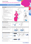
1
Planmeca Sovereign Classic ™ EN user's manual 10032652_2 TABLE OF CONTENTS 1 INTRODUCTION ..............................................................................................1 2 ASSOCIATED DOCUMENTATION .................................................................1 3 TRAINING ........................................................................................................3 4 PREVENTIVE MAINTENANCE ........................................................................3 5 SYMBOLS ON PRODUCT LABELS ................................................................4 6 FOR YOUR SAFETY ........................................................................................7 6.1 6.2 7 Safety switches .......................................................................................................... 11 Chair movement restrictors ........................................................................................ 12 PLANMECA SOVEREIGN CLASSIC DENTAL UNIT ...................................13 7.1 Dental unit configurations ........................................................................................... 13 7.1.1 7.1.2 7.2 7.3 7.4 7.5 7.6 7.7 7.8 Detachable parts ........................................................................................................ 15 Applied parts .............................................................................................................. 18 Bowl ........................................................................................................................... 19 Monitor ....................................................................................................................... 20 USB connectivity ........................................................................................................ 21 Unit swivel .................................................................................................................. 22 iPad lightning dock ..................................................................................................... 23 7.8.1 7.8.2 7.9 7.10 Over-the-patient delivery with balanced instrument arms ......................................... 13 Over-the-patient delivery with hanging-tube instruments .......................................... 14 Attaching lightning dock ............................................................................................ 23 Detaching lightning dock ........................................................................................... 24 Planmeca ProX X-ray unit .......................................................................................... 24 Zeiss OPMI pico microscope ..................................................................................... 25 8 OPERATING LIGHT .......................................................................................26 9 INSTRUMENT SYSTEM ................................................................................27 9.1 9.2 Over-the-patient (OP) delivery arm ............................................................................ 27 Instrument console ..................................................................................................... 28 9.2.1 9.2.2 9.3 9.4 Quick-connector hoses .............................................................................................. 30 Tray tables ................................................................................................................. 31 9.4.1 9.4.2 9.5 10 Tray table for balanced-arm instrument console ....................................................... 31 Tray table for hanging-tube instrument console ........................................................ 32 Instruments ................................................................................................................ 33 SUCTION SYSTEM ........................................................................................34 10.1 10.2 11 Balanced-arm instrument console ............................................................................. 28 Hanging-tube instrument console .............................................................................. 29 Suction handpieces .................................................................................................... 34 Suction arm with Flexy-holder .................................................................................... 34 PATIENT CHAIR ............................................................................................37 11.1 11.2 11.3 11.4 11.5 General ...................................................................................................................... 37 Trendelenburg position .............................................................................................. 37 Chair swivel ................................................................................................................ 38 Armrests ..................................................................................................................... 38 Headrest ..................................................................................................................... 39 11.5.1 11.5.2 User’s Manual Adjusting headrest height .......................................................................................... 39 Adjusting headrest angle ........................................................................................... 39 Planmeca Sovereign Classic i TABLE OF CONTENTS 11.5.3 12 CONTROL PANEL .........................................................................................41 12.1 12.2 Two control panels ..................................................................................................... 41 Control panel on instrument console .......................................................................... 41 12.2.1 12.2.2 12.2.3 12.2.4 12.3 13 Adjusting headrest for children or short patients ....................................................... 40 Overview ................................................................................................................... 41 Attaching control panel .............................................................................................. 41 Detaching control panel ............................................................................................. 42 Touch screen ............................................................................................................. 42 Control panel on Flexy-holder .................................................................................... 44 FOOT CONTROL ...........................................................................................45 13.1 13.2 13.3 Overview .................................................................................................................... 45 Knobs and pedal ........................................................................................................ 45 Wireless foot control ................................................................................................... 49 14 SWITCHING UNIT ON AND OFF ...................................................................51 15 CHECKING SOFTWARE VERSION ..............................................................52 16 OPERATING PATIENT CHAIR ......................................................................53 16.1 16.2 16.3 16.4 17 OPERATING DENTAL UNIT ..........................................................................57 17.1 17.2 17.3 17.4 17.5 17.6 17.7 18 Language ................................................................................................................... 57 Bowl rinse ................................................................................................................... 58 Cup fill ........................................................................................................................ 58 Timer .......................................................................................................................... 59 Door open .................................................................................................................. 59 Assistant call .............................................................................................................. 60 Planmeca SingLED operating light ............................................................................ 61 OPERATING INSTRUMENTS ........................................................................62 18.1 18.2 18.3 18.4 18.5 18.6 19 Manual operation ....................................................................................................... 53 Automatic operation ................................................................................................... 55 Trendelenburg position .............................................................................................. 56 Rinsing position .......................................................................................................... 56 Instrument logic .......................................................................................................... 62 Micromotor ................................................................................................................. 63 Turbine ....................................................................................................................... 66 Scaler ......................................................................................................................... 70 Polymerisation light .................................................................................................... 72 Intraoral camera ......................................................................................................... 73 PROGRAMMING ............................................................................................74 19.1 19.2 19.3 Introduction ................................................................................................................ 74 Automatic chair positions ........................................................................................... 75 Instrument settings ..................................................................................................... 76 19.3.1 19.3.2 19.3.3 19.3.4 19.3.5 19.4 19.5 Instrument speed/power reduction ............................................................................ 76 Instrument spray ........................................................................................................ 77 Chip blow ................................................................................................................... 77 Fibre optic light / LED light ........................................................................................ 78 Planmeca Lumion polymerisation light ...................................................................... 78 Timer settings ............................................................................................................. 79 Bowl rinse and cup fill ................................................................................................ 79 19.5.1 Adjusting cup fill and bowl rinse flow rates ................................................................ 79 ii Planmeca Sovereign Classic User’s Manual TABLE OF CONTENTS 19.5.2 19.5.3 19.6 19.7 19.8 19.9 20 Intensity of operating light .......................................................................................... 81 Door open / assistant call ........................................................................................... 82 Clock .......................................................................................................................... 83 Date ............................................................................................................................ 84 MAINTENANCE AND CLEANING .................................................................85 20.1 20.2 Cuspidor parts ............................................................................................................ 85 Filling disinfectant containers ..................................................................................... 86 20.2.1 20.2.2 20.3 20.4 20.5 20.6 20.7 Bowl ......................................................................................................................... 108 Water container ....................................................................................................... 109 Instrument flushing holder ....................................................................................... 109 Coarse filters ........................................................................................................... 110 Suction tube cleaning holder ................................................................................... 110 Cleaning suction system .......................................................................................... 111 20.9.1 20.9.2 20.9.3 20.9.4 20.9.5 20.9.6 20.9.7 20.10 20.11 20.12 20.13 Oil collector .............................................................................................................. 107 Cleaning cuspidor .................................................................................................... 108 20.8.1 20.8.2 20.8.3 20.8.4 20.8.5 20.9 When to use cleaning programs ................................................................................ 88 Before you start ......................................................................................................... 89 After cleaning ............................................................................................................ 91 Short instrument flushing ........................................................................................... 92 Long instrument flushing ........................................................................................... 94 Suction cleaning ........................................................................................................ 96 Waterline cleaning ..................................................................................................... 98 Extensive flushing ................................................................................................... 103 Cleaning instruments ............................................................................................... 104 Cleaning dental unit surfaces ................................................................................... 104 Cleaning instrument console .................................................................................... 107 20.7.1 20.8 Filling PlanClear container ........................................................................................ 86 Filling Orotol Plus container ...................................................................................... 86 Continuous cleaning ................................................................................................... 87 Flushing and cleaning programs ................................................................................ 88 20.4.1 20.4.2 20.4.3 20.4.4 20.4.5 20.4.6 20.4.7 20.4.8 21 Duration of bowl rinsing ............................................................................................. 80 Duration of cup filling ................................................................................................. 80 In the morning ......................................................................................................... 111 After each patient .................................................................................................... 111 After the working day ............................................................................................... 111 Weekly cleaning procedures ................................................................................... 112 Cleaning suction handpieces .................................................................................. 112 Dürr CAS1 deposit cup ............................................................................................ 113 VS/A container ........................................................................................................ 113 Cleaning Planmeca ProX ......................................................................................... 113 Cleaning Planmeca ProSensor ................................................................................ 114 Cleaning external PC ............................................................................................... 114 Cleaning Zeiss OPMI pico ........................................................................................ 114 HELP & ERROR MESSAGES .....................................................................115 21.1 21.2 21.3 Overview .................................................................................................................. 115 Help messages ........................................................................................................ 116 Error messages ........................................................................................................ 118 22 MAINTENANCE PARTS ..............................................................................121 23 UNIT DISPOSAL ..........................................................................................123 24 TECHNICAL SPECIFICATIONS ..................................................................124 24.1 Dimensions .............................................................................................................. 127 User’s Manual Planmeca Sovereign Classic iii TABLE OF CONTENTS 24.2 FCC Class B Notice for wireless foot control ........................................................... 136 The manufacturer, assembler and importer are responsible for the safety, reliability and performance of the unit only if: - installation, calibration, modification and repairs are carried out by qualified and authorized personnel - electrical installations are carried out according to the appropriate requirements such as IEC 60364 - equipment is used according to the operating instructions. Planmeca pursues a policy of continual product development. Although every effort is made to produce up-to-date product documentation this publication should not be regarded as an infallible guide to current specifications. We reserve the right to make changes without prior notice. COPYRIGHT PLANMECA Publication number 10032652 Revision 2 Released 04 April 2014 iv Planmeca Sovereign Classic User’s Manual INTRODUCTION 1 INTRODUCTION The Planmeca Sovereign Classic dental unit is an electrically controlled dental device that consists of a patient chair, cuspidor, delivery arm, dental instruments and an operating light. The Planmeca Sovereign Classic dental unit is meant to be used for dental treatment by dental care professionals. This manual describes the Planmeca Sovereign Classic dental unit and how to use it. Depending on the configuration of your dental unit, this manual may contain parts that do not apply to your dental unit. Please read this manual carefully before using the unit. NOTE The use of the Planmeca Sovereign Classic dental unit is allowed only under the supervision of the dental care professional. NOTE This manual is valid for Sovereign Classic software version 1.0.1 or newer. NOTE In error situations, this manual is the primary source of information. NOTE For information on OEM products, please refer to OEM documentation. 0598 The Planmeca Sovereign Classic dental unit fulfills the requirements of Directive 93/42/EEC. Classification according to European Council Directive 93/ 42/EEC: Class IIA. The settings and values shown in this guide are only examples and should not be interpreted as recommended values unless otherwise stated. 2 ASSOCIATED DOCUMENTATION Planmeca Sovereign Classic dental unit is delivered with the following manuals: User’s Manual • User’s manual For dental care professionals. Describes the dental unit and its different parts as well as instructs how to operate and clean the dental unit. • Installation manual For service personnel. Describes how to install the dental unit. • Technical manual For service personnel. Gives instructions for service situations. Planmeca Sovereign Classic 1 ASSOCIATED DOCUMENTATION The intraoral X-ray unit Planmeca ProX can be installed to Planmeca Sovereign Classic. Planmeca ProX is an option that is available in selected market areas. Please contact your local sales representative for details. Planmeca ProX is delivered with the following manuals: • User’s manual For dental/health care professionals. Describes the intraoral X-ray unit and its different parts as well as instructs how to operate and clean the X-ray unit. • Installation manual For service personnel. Describes how to install the intraoral X-ray unit. • Technical manual For service personnel. Gives instructions for service situations. The Planmeca ProSensor sensor is delivered with the following manuals: • User’s manual For dental care professionals. Describes the sensor that is intended to be used for capturing digital intraoral X-ray images and instructs how to use it. • Installation manual For service personnel. Describes how to install the sensor. The Panasonic intraoral camera is delivered with the following manual: • User’s and installation manual For dental care professionals and service personnel. Describes the Panasonic intraoral camera as well as instructs how to operate and clean the camera. Also describes how to install the Panasonic intraoral camera to the dental unit. Before using the dental unit water and waterline disinfectant Planmeca PlanClear, read the disinfectant’s material safety data sheet. Before using the suction system disinfectant Dürr Orotol Plus, read the disinfectant’s material safety data sheet. Before using an instrument, read the instrument’s user’s manual. For a full list of accessories, refer to the Planmeca product price list. 2 Planmeca Sovereign Classic User’s Manual TRAINING 3 TRAINING A hands-on user’s training is given in connection with the dental unit installation. 4 PREVENTIVE MAINTENANCE To guarantee the dental unit’s proper operation, the dental unit must be checked and serviced once a year by a qualified Planmeca service technician. User’s Manual Planmeca Sovereign Classic 3 SYMBOLS ON PRODUCT LABELS 5 SYMBOLS ON PRODUCT LABELS Packaging symbols (Standard ISO 780 and ISO 15223-1) 1. 2. 3. 4. 5. 6. 1. This side up 2. Fragile 3. Keep dry 4. Temperature limitation 5. Air pressure limitation 6. Humidity limitation Packaging symbol. The number of stacked packages is limited to 2 due to the weight of the package. Type B equipment (Standard IEC 60878). Type B applied parts for specified dental instruments (Standard IEC 60878). Type BF applied part for specified dental instruments (Standard IEC 60878). Alternating current (Standard IEC 60878). On/off switch Attention, consult accompanying documents (Standard ISO 7010). General warning (Standard ISO 7010). Warning, crushing hazard: hand (Standard IEC 60878). Warning, hot surface (Standard ISO 7010). 4 Planmeca Sovereign Classic User’s Manual SYMBOLS ON PRODUCT LABELS To avoid risk of electric shock, this equipment must only be connected to a supply mains with protective earth. Chemical hazard. Irritant as defined by Directive 67/548/ EEC. Planmeca PlanClear is a disinfectant for the water and waterlines. Only put Planmeca PlanClear in the container. The container must be filled with Orotol Plus, which is a disinfectant for the suction tubes and suction lines. IPX1 Protected against dripping water (Standard IEC 60529). Disposable item. Do not reuse (Standard ISO 7000). Separate collection for electrical and electronic equipment according to Directive 2002/96/EC (WEEE). Date of manufacture (Standard IEC 60878). Protective earth (Standard IEC 60878). Radio certification (Japanese Radio Law certification symbol). Indicates the direction of rotation for increasing/ decreasing the water flow for the bowl rinse and cup fill. User’s Manual Planmeca Sovereign Classic 5 SYMBOLS ON PRODUCT LABELS The multiple socket outlet (MSO) is reserved for medical devices that comply with the IEC 60601-1 standard. The MSO is available as an option. Turn the main switch off before servicing the unit LBL-G-012 Note that the mains voltage is always present at the mains terminal under the cover, when the unit is switched on. Do NOT open the cover. CAUTION Only connect equipment approved Planmeca to the multiple socket outlet. by WARNING Do not connect a multiple socket outlet or extension cord to the system. WARNING The unit contains live mains voltage parts. Always first turn off the power to the unit externally before attempting to service the lift-motor, backrest motor, or any parts inside the electronics control box. The power supply must be disconnected externally from, for example, a fuse or a mains switch. The fuse or main switch must be lockable into off-position. Turning off the unit from its own mains switch DOES NOT cut off the mains voltage from all internal nodes. The power supply for the Planmeca ProX X-ray unit, Planmeca ProSensor PoE port and external PC must be disconnected externally by removing the plug from the socket outlet. 6 Planmeca Sovereign Classic User’s Manual FOR YOUR SAFETY 6 FOR YOUR SAFETY NOTE National regulations concerning the quality of dental water and dental air must be followed when using the Planmeca Sovereign Classic dental unit. NOTE The air used by the Planmeca Sovereign Classic dental unit instruments must be dry, clean and oil-free. NOTE The water used by the Planmeca Sovereign Classic dental unit instruments and cup fill are to be used for rinsing only. For more information, please contact your local Planmeca dealer. NOTE The main water feed must be turned off when the dental unit is not in use. NOTE Before switching on the dental unit, make sure that the main water feed, air pressure and suction motor are turned on. NOTE The user must monitor the microbial load of the water used by the dental unit. Biotest Plus (by Alpro Medical GmbH) or equivalent test can be used for this purpose. NOTE If a method such as electro-chemical activation is used to disinfect the dental unit water and waterlines, disinfection with Planmeca PlanClear is not necessary. For more information, please contact your local Planmeca dealer. NOTE EMC requirements have to be considered, and the equipment must be installed and put into service according to the specific EMC information provided in the accompanying documents. NOTE Portable and mobile RF communications equipment can affect the Planmeca Sovereign Classic dental unit. NOTE The Planmeca Sovereign Classic dental unit shall only be connected to a trusted private network (and not, for example, the Internet). NOTE Never place heavy objects or containers of liquid on any part of the unit or hang objects from the unit’s arm structures. NOTE Electromagnetic interference between the equipment and other devices can occur in very extreme conditions. Do not use the equipment in close conjunction with sensitive devices, or devices creating high electromagnetic disturbances. 1, 5 m NOTE Care should be taken when other movable equipment is used in conjunction with the Sovereign Classic dental unit. PATIENTAREAEPS User’s Manual NOTE External equipment intended for connection to signal input, signal output or other connectors, shall comply with relevant IEC standard (e.g. IEC 60950 for IT equipment and the IEC 60601 series for medical electrical equipment). In addition, all such combinations - systems - shall comply with the IEC 60601-1 standard. Equipment not complying to IEC 60601-1 shall be kept outside the patient area (see figure). Any person who connects external equipment to signal input, signal output or other connectors has formed a system and is therefore responsible for the system to comply with the requirements of IEC 606011. If in doubt, contact a qualified technician or your local representative. Planmeca Sovereign Classic 7 FOR YOUR SAFETY CAUTION If the unit has been stored at temperatures below + 10°C for more than a few hours, time must be allowed for the unit to reach room temperature in the original packing before connecting the unit to the mains voltage. CAUTION Before using the dental unit, ensure that the instruments have been properly flushed and that the suction tubes as well as the dental unit’s waterlines have been cleaned as instructed in this manual. CAUTION Guide the patient to sit on the chair. Make sure no one sits on the legrest, the backrest or any other part of the dental unit. CAUTION Do not touch the patient when opening the cuspidor door. CAUTION A faulty or broken dental unit must not be used. CAUTION Drops of water on the touch screen might disturb the functioning of the screen. CAUTION Lock the touch screen from the Maintenance window before using a table-top instrument. CAUTION Make sure that the cup fill tube is always properly in its position by the cup holder. CAUTION The light source of the SingLED operating light may cause retinal injury if viewed upon directly. Protect the patient’s and dental treatment staff’s eyes with protective glasses that block high-energy visible light (HEV light), or limit the direct exposure to 10 minutes. CAUTION Electrosurgical knives generate strong radio frequency signals that can interfere with the functions of other electronic equipment. Although the Planmeca Sovereign Classic dental unit is tested to be very interferencetolerant, and is not known to be disturbed by signals generated by the XO electrosurgical knife, we recommend that the dental unit be shut down when the electrosurgical knife is used. CAUTION The use of the XO electrosurgical knife may affect the function of an implanted pacemaker or defibrillator. Please refer to the manufacturer’s own documentation. CAUTION Do not use the scaler or the polymerisation light on patients with cardiac pacemakers. The instrument can cause disturbance on the pacemaker’s function. CAUTION Do not use the equipment in close conjunction with anaesthetic gas or in highly oxygenated environments (oxygen content >25%). 8 Planmeca Sovereign Classic User’s Manual FOR YOUR SAFETY CAUTION Do not perform other maintenance procedures than those instructed in this manual. CAUTION When servicing the unit, always switch the unit off. CAUTION Note that in extreme conditions the temperature of the chair lift and backrest motors might rise significantly. DO NOT TOUCH THE MOTORS! CAUTION Note that the mains voltage is always present at the mains terminal under the main control PCB cover, even if the unit is switched off from its own mains switch. The power supply must be disconnected externally from, for example, a fuse or a mains switch. The fuse or main switch must be lockable into off-position. CAUTION If the drain is blocked, the dental unit might overflow with contaminated water and excessive water could flow onto the floor. Shut down the unit and contact your property's caretaker and a qualified Planmeca service technician. CAUTION When a water leak is detected, help message HE_4004 is displayed. Turn off the clinic’s main water tap and contact a qualified Planmeca service technician. CAUTION A power cut will shut down the softwarecontrolled backflow prevention system. If you are using a turbine without a built-in backflow prevention system, contaminated water could be released in the patient’s mouth in the event of a power cut. WARNING No modification of this dental unit is allowed. WARNING Only instruments or equipment approved by Planmeca may be connected to this dental unit. WARNING Do not simultaneously touch the patient and the PC. User’s Manual Planmeca Sovereign Classic 9 FOR YOUR SAFETY WARNING Do not touch the patient when the cuspidor door is open. WARNING The patient must not be in contact with instruments when the patient is resuscitated with a defibrillator. WARNING The worm screw securing nut in the chair lift motor must always be attached to the worm screw and must not be removed. If the securing nut is faulty or displaced, immediately stop using the dental unit and contact a qualified Planmeca service technician. The worm screw nut is marked with an arrow in the picture below. 10 Planmeca Sovereign Classic User’s Manual FOR YOUR SAFETY 6.1 Safety switches Care should be taken when driving the patient chair from one position to another. Obstructions in the patient chair’s line of movement activate safety switches that stop the motorised movements. The safety switches and their functions are described below. 1. Backrest An obstruction between the backrest and the floor when driving down the chair and/or the backrest stops downwards chair and backrest movements. Remove the obstruction to resume normal operation. 2. Chair An obstruction between the chair and the floor stops downwards chair and backrest movements. Remove the obstruction to resume normal operation. 3. Legrest An obstruction between the legrest and the floor stops downwards chair and backrest movements. Remove the obstruction to resume normal operation. 4. OP delivery arm joint An obstruction between the OP delivery arm and the chair when driving up the chair stops upwards chair movements. Remove the obstruction to resume normal operation. 5. OP delivery arm An obstruction between the OP delivery arm and the chair when driving up/down the chair stops up-/ downwards chair movements. Remove the obstruction to resume normal operation. 5 4 1 3 2 SC_UM_20.eps User’s Manual Planmeca Sovereign Classic 11 FOR YOUR SAFETY 6.2 Chair movement restrictors Some dental unit parts are equipped with sensors that recognise when the part is in its home position. When the part is not in the home position, chair movements are disabled or restricted. 1. Bowl The bowl is above the patient chair and stops upward chair movements. Return the bowl to its home position to resume normal operation. The home position is presented in section 7.4 “Bowl” on page 19. 2. Armrests When the armrests are turned outwards, all chair movements are disabled. Turn the armrest inwards so that it is aligned with the chair to resume normal operation. 3. Chair swivel Depending on the chair swivel angle, the up-/ downwards movements of the chair and backrest might be restricted. Swivel the chair back to its home position to resume normal operation. The home position is presented in section 11.3 “Chair swivel” on page 38. 1 2 3 SC_UM_20_2.eps 12 Planmeca Sovereign Classic User’s Manual PLANMECA SOVEREIGN CLASSIC DENTAL UNIT 7 PLANMECA SOVEREIGN CLASSIC DENTAL UNIT 7.1 Dental unit configurations 7.1.1 Over-the-patient delivery with balanced instrument arms 11 10 9 8 12 7 6 13 5 4 1 SC_1_1.eps 2 3 1. Cuspidor 8. Balanced instrument arms 2. Suction arm 9. Operating light 3. Foot control 10. Over-the-patient (OP) delivery arm 4. Patient chair 11. Monitor 5. Tray table 12. ProX X-ray unit (optional, not available in all market areas) 6. Control panel 13. Bowl 7. Instrument console User’s Manual Planmeca Sovereign Classic 13 PLANMECA SOVEREIGN CLASSIC DENTAL UNIT 7.1.2 Over-the-patient delivery with hanging-tube instruments 11 10 9 12 13 8 7 1 6 2 5 4 SC_OP_HT.eps 3 1. Cuspidor 8. Patient chair 2. Suction arm 9. Operating light 3. Foot control 10. Over-the-patient (OP) delivery arm 4. Hanging-tube instruments 11. Monitor 5. Control panel 12. ProX X-ray unit (optional, not available in all market areas) 6. Instrument console 13. Bowl 7. Tray table 14 Planmeca Sovereign Classic User’s Manual PLANMECA SOVEREIGN CLASSIC DENTAL UNIT 7.2 Detachable parts The following detachable components are marked with a manufacturer trademark. Do not perform dental treatment when either or both of these are detached. • Balanced instrument arms • Headrest ER X FURTH MAULL DO TP NO The following detachable components are not critical to operation. • User’s Manual Hygienic membrane Planmeca Sovereign Classic 15 PLANMECA SOVEREIGN CLASSIC DENTAL UNIT Armrests • Instrument flushing holder SC_UM_26.eps • Suction tube cleaning holder SC_UM_25.eps • Cup fill tube SC_UM_29.eps • 16 Planmeca Sovereign Classic User’s Manual PLANMECA SOVEREIGN CLASSIC DENTAL UNIT Bowl, filter and filter cap • Dentist’s instruments and hoses SC_UM_44.eps SC_UM_33.eps • • User’s Manual Suction tubes Planmeca Sovereign Classic 17 PLANMECA SOVEREIGN CLASSIC DENTAL UNIT Assistant’s instruments and hoses • Water container (1) and technical cap (2) SC_UM_47.eps • SC_UM_48.eps 2 7.3 1 Applied parts Applied parts are parts of the dental unit that in normal treatment situations come into contact with the patient. The applied parts of the Planmeca Sovereign Classic dental unit include the instruments, the patient chair with upholstery, the armrests, the outside of the cuspidor including bowl, and the instrument console. 18 Planmeca Sovereign Classic User’s Manual PLANMECA SOVEREIGN CLASSIC DENTAL UNIT 7.4 Bowl The glass bowl is attached to the top of the cuspidor. It can be rotated 370° around its axis according to the figure below. NOTE Always place the bowl in home position (as illustrated in the picture below). NOTE Make sure that the bowl is not above the patient chair when you drive the chair upward. SC_UM_3.eps CAUTION Do not allow the patient to grab the bowl when getting seated or getting up from the patient chair. User’s Manual Planmeca Sovereign Classic 19 PLANMECA SOVEREIGN CLASSIC DENTAL UNIT If the bowl assembly for some reason comes off the cuspidor you can put it back as follows: 7.5 1. Place the ring to the underside of the bowl assembly. 2. Make sure that the peg goes into the slot as shown in the picture below. 3. Push the bowl downwards at the same time making sure that no cables are squeezed. 4. Turn the bowl assembly into place. You will know that it is in place when you hear the clicking sound of the micro switch. Monitor The monitor can be moved from its handle. CAUTION Do not allow the patient to grab the monitor handle or monitor arm when getting seated or getting up from the patient chair. Clean the monitor according to the instructions in section 20.6 “Cleaning dental unit surfaces” on page 104. NOTE Never spray water on the monitor or the PC. For more information, see the monitor’s user’s manual. 20 Planmeca Sovereign Classic User’s Manual PLANMECA SOVEREIGN CLASSIC DENTAL UNIT 7.6 USB connectivity The Planmeca Sovereign Classic dental unit has several USB ports for different purposes. 1. The USB port on the instrument hose slot on the backside of the instrument console is dedicated for the intraoral camera. A Planmeca service technician can relocate this USB port to any slot in the console. 2. Optionally, a USB port can be installed on the backside of the instrument console to offer a USB connection for downloading/uploading your personal settings. This feature will be available in the future. 3. The USB port inside the cuspidor enables the use of an intraoral camera on the assistant side. At installation, the position for the intraoral camera is selected (either USB port 1 or 3) and the port that is selected is linked to the external PC. NOTE Connect only intraoral cameras supplied by Planmeca to the dental unit. 1 3 User’s Manual SC_UM_49_2.eps 2 Planmeca Sovereign Classic 21 PLANMECA SOVEREIGN CLASSIC DENTAL UNIT 7.7 Unit swivel The Planmeca Sovereign Classic dental unit can be swivelled manually ±120°. (120°) (120°) 60° 60° SC_UM_35.eps SC_UM_36_3.eps Pull the lever on the unit base to unlock the base and swivel the dental unit to the desired position. Lock the base by pushing the handle back in. For an overview of how the cuspidor can be positioned, see section “Cuspidor positions” on page 130. For detailed measurements on the unit swivel area, see section “Top view” on page 133. Also the chair can be swivelled, see section 11.3 “Chair swivel” on page 38. 22 Planmeca Sovereign Classic User’s Manual PLANMECA SOVEREIGN CLASSIC DENTAL UNIT 7.8 iPad lightning dock A lightning dock for your iPad where you can charge its battery can be connected to either side of the instrument console. The lightning dock is only to be used together with the iPad, so if you remove the iPad, always remove the lightning dock, too. CAUTION The iPad may break if it is dropped on the floor. NOTE The lightning dock supports a limited range of iPad models. For details, please contact your local Planmeca dealer. 7.8.1 Attaching lightning dock Push the lightning dock arm into the attachment opening in a position where the arm is rotated approx. 30° forward as shown in the figure (1). Attach the lightning dock to the instrument console by rotating the lightning dock arm counterclockwise (when the lightning dock is placed on the right side of the console) or clockwise (when the lightning dock is placed on the left side of the console) until you hear a click (2). SC_UM_50.eps 1 User’s Manual 2 Planmeca Sovereign Classic 23 PLANMECA SOVEREIGN CLASSIC DENTAL UNIT 7.8.2 Detaching lightning dock To make the detachment easier, turn the iPad screen outward (see figure). SC_UM_51.eps 1 Press the locking button located underneath the lightning dock arm (1) and turn the arm approximately 30° clockwise (2) (when the lightning dock is placed on the right side of the console) or counterclockwise (when the lightning dock is placed on the left side of the console). 2 Detach the lightning dock by pulling the arm out from the instrument console (3). 3 7.9 Planmeca ProX X-ray unit The Planmeca ProX X-ray unit can be mounted to the Planmeca Sovereign Classic dental unit pylon. SC_UM_2.eps NOTE The Planmeca ProX X-ray unit is an option and is not available in all market areas. CAUTION Drive the chair carefully when positioning the ProX X-ray unit. CAUTION Do not drive the chair during the exposure. CAUTION Do not touch the external PC and the patient at the same time. CAUTION Move the ProX X-ray unit behind the pylon when it is not being used. For more information about Planmeca ProX, see Planmeca ProX User’s Manual. 24 Planmeca Sovereign Classic User’s Manual PLANMECA SOVEREIGN CLASSIC DENTAL UNIT 7.10 Zeiss OPMI pico microscope The Zeiss OPMI pico dental microscope can be mounted to the Planmeca Sovereign Classic dental unit pylon. NOTE The Planmeca Intra X-ray unit and the Zeiss OPMI pico dental microscope can not simultaneously be attached to the Planmeca Sovereign Classic dental unit. CAUTION Do not drive the chair when a patient is under the microscope. For more information about Zeiss OPMI pico, see the manufacturer’s own documentation. User’s Manual Planmeca Sovereign Classic 25 OPERATING LIGHT OPERATING LIGHT SingLED13.eps 8 The Planmeca SingLED operating light features a “no touch” function through an infrared light cell detecting hand movements. Wave your hand shortly in front of the sensors (1) to switch on/off the operating light. It will switch on/off the light after you have moved your hand away from the sensor activation area. Also, you will hear a signal tone. Once the operation light is lit, keep your hand longer in front of the sensors to adjust the brightness of the light. The adjustment range is from 5% to 100% in steps of 5 percentage points. You will hear a signal tone when the maximum/minimum brightness is reached. NOTE The control panel or foot control can be used alongside the sensor to switch the operating light on/ off and to adjust the intensity. For more information, see section 17.7 “Planmeca SingLED operating light” on page 61. 1 NOTE Planmeca SingLED can also be switched on/off by pressing the on/off switch at the back of the operating light. CAUTION Do not allow the patient to grab the Planmeca SingLED operating light or its arm when getting seated or getting up from the patient chair. 26 Planmeca Sovereign Classic User’s Manual INSTRUMENT SYSTEM 9 INSTRUMENT SYSTEM 9.1 Over-the-patient (OP) delivery arm The OP delivery arm is attached to the top of the dental unit and swings over the chair. CAUTION Do not lean on the OP delivery arm. CAUTION Do not allow the patient to grab the OP delivery arm when getting seated or up from the patient chair. The instruments can be positioned using the handles on the instrument console. The rotation area of the delivery arm, instrument console and the control panel are shown in the illustrations below. SC_UM_4.eps The following presents the OP delivery arm with a balanced-arm instrument console. SC_UM_58.eps The following presents the OP delivery arm with a hanging-tube instrument console. User’s Manual Planmeca Sovereign Classic 27 INSTRUMENT SYSTEM 9.2 Instrument console 9.2.1 Balanced-arm instrument console The console can be equipped with up to six dynamic instruments. A special feature of the Planmeca Sovereign Classic dental unit is that the syringe can be right- or left-mounted. A USB-device must be placed in the second instrument position from the right. SC_UM_21.eps Labels mark the positions of the syringe and the USBdevice. The other instruments can be positioned according to your own preferences. The control panel can be right- or left-mounted. sov_030 The instrument arms can be removed by pulling them out from their holders, for example, for cleaning. The arms are replaced simply by pushing them firmly into their places. When placing the instrument hose to the roller, bend the hook of the hose guide carefully and pass the hose over the roller. The balance of the instrument arms can be changed according to the weight of the instrument and personal preferences. Their flexibility can be adjusted as follows: 1. Pull out the roller. 3 Adj_D.eps 1 2 2. Adjust the balance of the instrument arm by moving the roller to the desired position. Note that by positioning the roller higher up the arm is lighter to bend. 3. Push in the roller to lock its position. NOTE When balancing / adjusting the instrument arms, bear in mind that the instruments shall under no circumstances fall over the patient. 28 Planmeca Sovereign Classic User’s Manual INSTRUMENT SYSTEM 9.2.2 Hanging-tube instrument console The console can be equipped with up to six dynamic instruments. A special feature of the Sovereign Classic dental unit is that the syringe can be right- or leftmounted. A USB-device must be placed in the second instrument position from the right. Labels mark the positions of the syringe and the USBdevice. The other instruments can be positioned according to your own preferences. SC_UM_22.eps Both the control panel and the tray table can be right- or left-mounted. SC_UM_57.eps The instrument holders can be removed by pulling them out from their openings, for example for cleaning. The holders are replaced simply by pushing them firmly into their places. The angle of the instrument holder can be slightly adjusted. SC_UM_56.eps 1 2 By slightly tightening the screws (1, 2) under the instrument console you can make the adjustment of the instrument holders more rigid. By tightening the screws completely you can lock the angle of the instrument holder. Note that you have to tighten both screws equally, otherwise you may no longer be able to place the instrument holders to the console. Similarly, you can untighten the screws to unlock the angle or loosen the adjustment of the instrument holders. User’s Manual Planmeca Sovereign Classic 29 INSTRUMENT SYSTEM 9.3 Quick-connector hoses The instruments are equipped with quick-connector hoses to be connected to the instrument console. Insert the hose to its place so that the locking mechanism is facing down, and pull down the locking bar (1). Remember to pull up the locking bar (1) before removing the quick-connector hose. sov_009 When disconnecting the syringe, empty the water and air from the hose before opening the connector. The instrument location can be changed simply by removing the instrument with its hose and reconnecting it to the new place. The old instrument settings will remain the same despite the new location of the instrument hose. sov_008 1 The instrument selection can also be interchanged. The settings of the previously used instruments are stored in the memory, and are recalled when the instrument is reconnected. The syringe can be placed in the leftmost or rightmost position. The syringe can be used simultaneously with other instruments. Otherwise, there are no restrictions concerning the placing of the instruments on the console. NOTE Make sure that the locking bar is properly locked to the console to avoid any leakage. NOTE Always make sure that the instrument hose is correct for the used instrument. The control system identifies the instrument hose, not the instrument. The control system does not recognise the instrument change, for example, replacement of a turbine with an air motor. NOTE The instrument sealings must be correct and unbroken, and the instrument must be attached properly to the hose connector. The leakage between the instrument and connector causes leakage air to drift into the hose lining. NOTE A scaler requires additional electronics and the scaler type can not be changed without changing electronics. 30 Planmeca Sovereign Classic User’s Manual INSTRUMENT SYSTEM 9.4 9.4.1 Tray tables Tray table for balanced-arm instrument console 2 The tray table is attached to the mounting arm with a magnetic connector and can easily be attached and detached. You can rotate the table 360° to the desired position. The maximum weight limit on the tray is 2 kilograms (4,4 lbs). SC_UM_23.eps 1 The tray mounting arm is attached to the instrument console with a quick-connector. The tray assembly can be removed from the instrument console as follows. Pull the ring of the locking mechanism outwards (1) and pull the tray arm away from its position (2). SC_UM_24.eps The mounting arm can be attached to the instrument console by pushing it to its position. User’s Manual Planmeca Sovereign Classic 31 INSTRUMENT SYSTEM 9.4.2 Tray table for hanging-tube instrument console The tray mounting arm is attached to the instrument console with a quick-connector, enabling an easy attachment and detachment of the tray table. You can rotate the table 360° to the desired position. The maximum weight limit on the tray is 2 kilograms (4,4 lbs). S203_2.eps The quick-connectors make it easy to, for example, change from left-handed to right-handed operation. 2 3 To detach the tray table, press the locking button located underneath the tray mounting arm (1) and turn the tray mounting arm approximately 30° clockwise (2) (when the tray table is placed on the left side of the console) or counterclockwise (when the tray table is placed on the right side of the console). Detach the tray table by pulling the arm out from the instrument console (3). 1 To attach the tray table, push the tray mounting arm into the attachment opening in a position where the tray mounting arm is rotated approx. 30° backward as shown in the figure (1). Attach the tray mounting arm to the instrument console by rotating the tray mounting arm counterclockwise (when the tray table is placed on the left side of the console) or clockwise (when the tray table is placed on the right side of the console) until you hear a click (2). S202_2.eps 1 2 32 Planmeca Sovereign Classic User’s Manual INSTRUMENT SYSTEM 9.5 Instruments The instrument console has six instrument positions. The following instruments are available for Planmeca Sovereign Classic: • Syringe • Turbine • Micromotor • Scaler • Polymerisation light • Intraoral camera The syringe can be placed in the leftmost or rightmost position. The syringe can be used simultaneously with other instruments. Otherwise, there are no restrictions concerning the placing of the instruments on the console. The control panel will give you detailed guidance while using the instruments. User’s Manual Planmeca Sovereign Classic 33 SUCTION SYSTEM 10 SUCTION SYSTEM 10.1 Suction handpieces When a saliva or high-volume suction handpiece is lifted from its holder, the suction will automatically start. When the handpieces are returned, the suction will stop. 10.2 cattani.eps durr1.eps durr2.eps When you are using the suction handpiece, the suction can be controlled by sliding the adjuster up or down. Suction arm with Flexy-holder The suction handpieces are placed in the Flexy-holder. The Flexy-holder is a suction holder with integrated control panels that enable you to control selected functions of the dental unit. For more information on the control panel, see section 12.3 “Control panel on Flexyholder” on page 44. The Flexy-holder is attached to the suction arm, which in its turn is attached to the cuspidor. 2 SC_UM_6.eps 1 34 Planmeca Sovereign Classic 3 The Flexy-holder has three openings. In one you place the assistant’s syringe and the suction handpieces are placed in the two remaining openings. In addition, one or two supplementary holders can be placed on either side of the Flexy-holder. The supplementary holder can be equipped with a USB intraoral camera or a polymerisation light. The picture shows the default positions for the suction handpieces and syringe. To change the positions, please contact a qualified Planmeca service technician. High-volume suction handpiece Saliva suction handpiece Syringe User’s Manual SUCTION SYSTEM The suction tube, instrument and supplementary holders can be removed from the Flexy-holder, for example for cleaning. Remove the suction tube holder by pulling it downward from the Flexy-holder. To replace it, push it firmly into its place. C A B D Remove the roller from the suction tube holder by pulling it away from the holder. To replace it, push it firmly into its place. User’s Manual Planmeca Sovereign Classic 35 SUCTION SYSTEM D A B C Remove the instrument holder by squeezing it from the bottom and at the same time lifting it upward. To replace it, squeeze the holder and insert it into its place. Remove the supplementary holder by pulling it out from the Flexy-holder. To replace it, push it firmly into its place. C B A D For cleaning instructions, see section 20.9.6 “Dürr CAS1 deposit cup” on page 113. 36 Planmeca Sovereign Classic User’s Manual PATIENT CHAIR 11 PATIENT CHAIR 11.1 General The Planmeca Sovereign Classic patient chair is integrated with the floor-mounted unit which gives plenty of room under the chair allowing the dentist and the assistant to move their legs freely while sitting down. Integrating the chair with the unit allows the chair to be raised high for a good working position. SC_UM_7_2.eps When you drive the backrest down, the seat follows the movements of the backrest and tilts accordingly. This ensures that the patient’s head stays in the correct position throughout the movement. CAUTION Make sure no one sits on the legrest or the backrest. 11.2 Trendelenburg position The Trendelenburg position is used in the event of a patient collapsing. The chair is driven to a position where the patient’s feet are higher than the head. SC_UM_8_2.eps For information on how to drive the chair to the Trendelenburg position, see section 16.3 “Trendelenburg position” on page 56. User’s Manual Planmeca Sovereign Classic 37 PATIENT CHAIR 11.3 Chair swivel SC_UM_27.eps The patient chair can be swivelled manually. Press either of the buttons on the chair underside (marked with arrows in picture) to release the lock and turn the chair to the desired position. You can swivel the chair within the movement limits shown in the picture. SC_UM_28_2.eps The chair’s home position is shown with solid black outlines. 11.4 Armrests Both armrests can be moved 90° outwards. Before you move the armrest horizontally you must lift it slightly to unlock it. The armrest can be locked into the positions presented in the picture. SC_UM_34.eps 38 Planmeca Sovereign Classic User’s Manual PATIENT CHAIR 11.5 11.5.1 Headrest Adjusting headrest height Cufl3_21.eps The height of the headrest can be adjusted by sliding it manually. NOTE The headrest can only be pulled out as far as to the MAX mark. 11.5.2 Adjusting headrest angle To adjust the angle of the headrest press the bar on the side of the headrest support to release the locking mechanism. Manually set the headrest to the required angle and release the bar. When adjusting, the headrest should be supported by hand. User’s Manual Planmeca Sovereign Classic 39 PATIENT CHAIR 11.5.3 Adjusting headrest for children or short patients The headrest can be turned around and repositioned for better head support for children or short patients. Pull the headrest out and turn it around so that the cushion faces backwards. Push the headrest back into the chair. Turn the cushion around (180° counterclockwise). Press the bar on the side of the headrest support to release the locking mechanism and position the headrest at the top of the chair. The headrest is now repositioned. To adjust the angle of the headrest press the locking bar. Manually set the headrest into the required position and release the bar. When adjusting support the headrest with your other hand. 40 Planmeca Sovereign Classic User’s Manual CONTROL PANEL 12 CONTROL PANEL 12.1 Two control panels The Planmeca Sovereign Classic dental unit has two control panels. The main control panel is located on the instrument console and the other one on the Flexy-holder. 12.2 12.2.1 Control panel on instrument console Overview The control panel on the instrument console features a touch screen and it can be used to control and program the instruments, the dental unit, and the chair. Also, maintenance procedures can be started from the control panel. The control panel is attached by the quick locks to the instrument console. CAUTION The control panel may break if it is dropped on the floor. SC_UM_9.eps 12.2.2 Attaching control panel To make the attachment easier, turn the control panel away from the attachment arm. Push the attachment arm into the attachment opening in a position where the attachment arm is rotated approx. 30° forward as shown in the figure (1). Attach the control panel to the instrument console by rotating the attachment arm counterclockwise (when the control panel is placed on the right side of the console) or clockwise (when the control panel is placed on the left side of the console) until you hear a click (2). 1 CAUTION Ensure that the dental unit works correctly after attaching the control panel. If needed, restart the dental unit. 2 User’s Manual Planmeca Sovereign Classic 41 CONTROL PANEL 12.2.3 Detaching control panel To make the detachment easier, turn the control panel outward (see figure). Press the locking button located underneath the attachment arm (1) and turn the attachment arm approximately 30° clockwise (2) (when the control panel is placed on the right side of the console) or counterclockwise (when the control panel is placed on the left side of the console). SC_UM_10.eps 1 2 Detach the control panel by pulling the arm out from the instrument console (3). 3 12.2.4 Touch screen The touch screen shows information related to the current operation and changes accordingly. Some of the buttons have indicator lights that show the status of that specific function. When the unit is in programming mode, the Program button is blue. In the programming mode, the setting to be changed is displayed on the touch screen, see section 19 “PROGRAMMING” on page 74. In the programming mode, a disabled or unselected function is displayed in grey. To enable or select the function, press the grey button and it will turn blue. A blue button means that the function is enabled or selected. In case of malfunction, an error code or a help message is displayed on the touch screen, see section 21 “HELP & ERROR MESSAGES” on page 115. 42 Planmeca Sovereign Classic User’s Manual CONTROL PANEL The picture below shows the main functions of the control panel when the dental unit is in idle state and no instrument is activated.8 1 7 2 8 3 4 9 5 10 6 CP4_Display_idle.eps User’s Manual 1. Icons for cleaning programs 6. Chair buttons 2. Time (display only) 7. OP light brightness (display only) 3. Date (optional, display only) 8. Wireless foot control battery (display only) 4. Maintenance button 9. Unit buttons 5. Assistant call (or alternatively Door open) 10. Program button Planmeca Sovereign Classic 43 CONTROL PANEL 12.3 Control panel on Flexy-holder The control panel on the Flexy-holder can be used for controlling the dental unit and the chair. When you press the Flexy button, the chair will be driven to the rinsing position. For more information, see section 16.4 “Rinsing position” on page 56. flexy_panel.eps 1 2 3 1. Chair buttons 2. Unit buttons 3. Flexy button 44 Planmeca Sovereign Classic User’s Manual FOOT CONTROL 13 FOOT CONTROL 13.1 Overview The Planmeca Sovereign Classic dental unit has one integrated foot control that operates the instruments, the unit and the chair. The foot control is available as a wireless and a standard version. NOTE All the foot control functions except instrument drive and manual chip blow can be performed on the control panel, too. CAUTION The foot control is a precision instrument. Do not stand on or apply unnecessary force to the foot control and its knobs. CAUTION Do not use the foot control in areas where liquids are likely to be present on the floor. 13.2 Knobs and pedal 1 3 2 NewFootctrl_3.eps 4 5 1. Handle 3. Centre knob 2. Left-side knob 4. Right-side knob 5. Pedal User’s Manual Planmeca Sovereign Classic 45 FOOT CONTROL The factory default functions of the foot control when the dental unit is equipped with a normal headrest, a standard pedal and no instrument is activated are presented below. (* = long push) C Backrest down * Chair up * B A Backrest up * D Chair down* ON / OFF operation light on/off Toggle USB-camera on/off Instrument related function Spit position Nurse call * fill (manual) Cup The functions that are activated by pushing the left-side or right-side knob up are configurable. The function for leftside-knob-down can be configured separately for a selection of instruments and the function depends on the selected instrument. Note that for the left-side-knob-down function you can only define one function per instrument position. Contact your Planmeca dealer. 46 Planmeca Sovereign Classic User’s Manual FOOT CONTROL Two foot control pedals are available: the standard pedal (1) and a slightly wider pedal (2) that functions like a gas pedal when you drive the instrument. That is, the further down you push the pedal, the higher the instrument speed is. The functional differences between the standard pedal and the wide pedal only apply to the micromotor, turbine and scaler and are described in the table below. 610_vos 610_vos SC_UM_54.eps Two types of pedal 1 2 Function Standard pedal Wide pedal Increase instrument speed Push pedal to left/right Push pedal down Change instrument spray type Push pedal down briefly Push pedal briefly to left/right Activate manual chip blow Push and hold pedal down Push and hold pedal to left/right Activate momentary spray Push pedal down briefly while driving instrument N/A For more information, see sections 18.2 “Micromotor” on page 63, 18.3 “Turbine” on page 66 and 18.4 “Scaler” on page 70. NOTE If you want to change from a standard pedal to the wide pedal, or vice versa, please contact a qualified Planmeca service technician. NOTE The differences in functionality only applies to the operation of some instruments, not the operation of the dental unit, chair or headrest. NOTE When the functionality of the foot control pedal is different for the standard pedal and the wide pedal, this is clearly indicated in this document. When the document refers to the foot control pedal in general without making this differentiation, the same functionality applies to both types of pedal, although the illustration only presents the standard pedal. User’s Manual Planmeca Sovereign Classic 47 FOOT CONTROL When an instrument is activated, the functions of the standard pedal depend on the used instrument. These instrument-specific functions are presented below. Symbol Symbol 48 Planmeca Sovereign Classic Function Instrument Drive instrument Micromotor, turbine, scaler, polisher Change spray 1 / 2 / OFF Micromotor, turbine, scaler Momentary cleaning water Polisher Manual chip blow; activated for as long as the pedal is pushed and held down Micromotor, turbine Function Instrument Start / stop instrument Unit controlled polymerisation light User’s Manual FOOT CONTROL 13.3 Wireless foot control NOTE The wireless foot control is an optional feature. The standard foot control and the wireless foot control can not be used simultaneously. Should such a situation occur, the standard foot control overrides the wireless foot control. When the wireless foot control has been idle for 30 minutes (default value), it goes into sleep mode. You can wake the foot control by pressing the foot control handle. You can also put the wireless foot control into sleep mode by pressing the foot control handle. Before using the wireless foot control, check the power level of its battery. The power level is indicated by a battery symbol on the control panel. NOTE The battery symbol can be hidden from the control panel. Contact your Planmeca dealer. Power level Sleep mode Full < 40% full < 20% full Symbol S195.eps When the wireless foot control battery is running low, you need to recharge the battery. To charge the foot control battery, connect the foot control to the power outlet using the provided cable and power adapter. The LEDs on the foot control blink green while the battery is being charged. 610_vos User’s Manual When the wireless foot control battery is full, and the foot control is connected to the power outlet, the LEDs on the foot control are a steady green. Planmeca Sovereign Classic 49 FOOT CONTROL CAUTION Do not charge the foot control battery while treating a patient. CAUTION The battery must be charged outside the patient area. CAUTION The battery charging area must be dry. Do not expose the charger to liquids. NOTE The power supply is marked and specified as a part of Planmeca Sovereign Classic. NOTE The batteries must be replaced only by a qualified Planmeca service technician. NOTE The foot control batteries must be removed whenever the foot control is stored for a longer period. The batteries must be removed only by a qualified Planmeca service technician. NOTE The standard foot control contains a radio device FCC: YII002 and IC: 9050A-002, and the wireless foot control contains a radio device FCC: YII001 and IC: 9050A-001. See also section 24.2 “FCC Class B Notice for wireless foot control” on page 136. 50 Planmeca Sovereign Classic User’s Manual SWITCHING UNIT ON AND OFF 14 SWITCHING UNIT ON AND OFF The ON/OFF switch (1) is located at the base of the Planmeca Sovereign Classic cuspidor, next to the suction arm. Press the switch once to switch the unit on. Press the switch a second time to switch it off. SC_UM_11.eps When Planmeca Sovereign Classic is switched on, the ON/OFF switch light is on. The control panel briefly shows the software version number. NOTE If your unit is equipped with a water heater, fill the cup once after switching the unit on to start the heating. Notice that when using the water heater, the water temperature can rise up to 49°C. NOTE At start-up, with the exception of start-up during maintenance procedures, instruments and suction tubes have to be in their holders. NOTE After the unit is switched on, it will take a few seconds until the Planmeca Sovereign Classic dental unit is ready for use. User’s Manual Planmeca Sovereign Classic 51 CHECKING SOFTWARE VERSION 15 CHECKING SOFTWARE VERSION Check the software version as follows: 1. Press Program. 2. Press About this unit. The following is displayed. NOTE 3. 52 Planmeca Sovereign Classic The following is an example only and does not necessarily portray the actual situation. Press OK to close the window. User’s Manual OPERATING PATIENT CHAIR 16 OPERATING PATIENT CHAIR NOTE All chair movements are blocked when an instrument, excluding syringe, is operated. NOTE The operating light intensity will decrease slightly when the chair is moving. NOTE As an alternative to the control panel buttons described below, the chair buttons on the Flexy-panel can be used to drive the chair. 16.1 Manual operation CAUTION When driving the chair near the upper limit, make sure that the console arm does not press or hit the patient. CAUTION When driving the backrest up, make sure that the patient’s hand or arm does not get squeezed between the armrest and the backrest. SC_UM_13.eps To drive the backrest down, hold your finger on the Backrest down button until the chair reaches the required position. SC_UM_14.eps To drive the backrest up, hold your finger on the Backrest up button until the chair reaches the required position. To drive the chair up, hold your finger on the Chair up button until the chair reaches the required position. SC_UM_15.eps NOTE Make sure that the bowl is not above the patient chair when driving the chair upward. User’s Manual Planmeca Sovereign Classic 53 OPERATING PATIENT CHAIR To drive the chair down, hold your finger on the Chair down button until the chair reaches the required position. SC_UM_16.eps NOTE In case the chair is equipped with the chair-mounted left/right suction arm, make sure the Flexy-holder is not above the cuspidor when driving the chair down. If the chair does not move downward and HE 3021 is displayed on the control panel, check that the chairmounted arm is not in the upmost position. This arm position prevents the chair from moving downward. SC_UM_15.eps Alternatively, you can adjust the position of the chair with the foot control. Push and hold the centre knob in the desired direction (see picture below). When the chair reaches the desired position, release the centre knob. You can steer the chair only in one direction at a time. 661100__vvooss sov_016 B SC_UM_14.eps C D ps SC_UM_13.eps A 54 Planmeca Sovereign Classic User’s Manual OPERATING PATIENT CHAIR 16.2 Automatic operation Automatic chair positions may be stored into memory. Press briefly the chair position button where the required position for the selected user is stored. The chair will move automatically to the preprogrammed position. To stop the chair from moving, either press any of the chair positioning buttons, push the foot control pedal in any direction, or push the foot control centre knob in any direction. C 661100__vvooss sov_016 B D A Alternatively, you can use the foot control to drive the chair to the automatic positions. Push the centre knob briefly to the position (A, B, C or D) where the preprogrammed chair position is stored. The chair will move automatically to the preprogrammed position. To stop the chair from moving before it reaches the preprogrammed position push the foot control pedal or the centre knob in any direction. SC_UM_17.eps The chair movement stops also when the stop plate (2) is pushed or when the backrest (1) is pressed upward. The chair can be driven normally after the possible obstruction has been removed. When the chair has reached its preprogrammed position the position can be adjusted. To drive the chair to the required position, use the foot control’s centre knob or the chair positioning buttons on the control panel in a nonautomatic mode. The operating light is programmed to switch on or off in preprogrammed positions. The light goes off when the chair begins to move to a position where the light has been programmed to be off, but goes on only after the chair has reached the programmed position, where the light has been programmed to be on. For more information on how to program the automatic positions, see section 19.2 “Automatic chair positions” on page 75. User’s Manual Planmeca Sovereign Classic 55 OPERATING PATIENT CHAIR 16.3 Trendelenburg position To drive the patient chair to the Trendelenburg position, press the Backrest down button until the backrest reaches its lower movement limit, and then press the Backrest down button again. The chair is driven to a position where the patient’s feet are higher than the head. 16.4 Rinsing position Press Rinsing position to move the chair to the preprogrammed rinsing position. The indicator light flashes throughout the movement. Filling the cup starts automatically, the bowl is rinsed, and the operating light goes off. NOTE Alternatively, you can press the Flexy button to move the chair to the preprogrammed rinsing position. NOTE The water in the dental unit is intended for rinsing only, not for drinking. When the chair stops in the rinsing position, the indicator light remains on. Press Rinsing position a second time to return to the working position. The chair remembers this previous position even though it has been moved into the rinsing position. Bowl rinsing starts automatically. The indicator light flashes throughout the movement. When the chair stops, the operating light turns back on, if it was on initially. NOTE Alternatively, you can press the Flexy button a second time to return to the working position. NOTE If you hold your finger on the Rinsing position button when moving the chair to the rinsing position, you will enter the position normally, but when the chair stops in the rinsing position the indicator light goes off and the chair does not remember its previous position. NOTE If you hold your finger on the Rinsing position button when the chair is in the rinsing position, the indicator light goes off, and the chair will forget the previous position (the return function is inactivated). 661100__vvooss sov_016 NOTE The unit can be set up so that the Rinsing position indicator light goes off and the previous position is forgotten, when you are driving from the rinsing position to a preprogrammed position. Next time you press Rinsing position, the chair will move to the rinsing position. Contact your Planmeca dealer. You can drive the chair to the rinsing position with the foot control by pushing down the right-side knob. To return to the working position push down the right-side knob again. For information on how to program the rinsing position, see section 19.2 “Automatic chair positions” on page 75. 56 Planmeca Sovereign Classic User’s Manual OPERATING DENTAL UNIT 17 OPERATING DENTAL UNIT 17.1 Language A selection of languages is available for the touch panel from software version 1.0.2 onward. Follow the steps below to change the language. 1. Press Program. 2. Press Language to open a list of available languages. The available languages are: 3. • English • Finnish • German • Spanish • French • Italian • Swedish • Hungarian • Czech • Danish • Norwegian • Russian • Japanese • Polish • Traditional Chinese • Simplified Chinese • Romanian • Arabic • Dutch • Portuguese Select a language by pressing it. Move up and down on the list by pressing the up/ down buttons. The list of languages closes and the language of your choice is displayed on the touch panel. NOTE The language can not be changed from the foot control. User’s Manual Planmeca Sovereign Classic 57 OPERATING DENTAL UNIT 17.2 Bowl rinse Control panel: Press Bowl rinse to rinse the bowl. Bowl rinsing can be stopped before it stops automatically by pressing Bowl rinse again. Flexy-holder: Press Bowl rinse / cup fill to rinse the bowl. Bowl rinsing can be stopped before it stops automatically by pressing Bowl rinse / cup fill again. The flow rate of the bowl rinse can be adjusted by turning the black knob inside the unit, see section 19.5.1 “Adjusting cup fill and bowl rinse flow rates” on page 79. The duration of bowl rinsing can be programmed, see section 19.5.2 “Duration of bowl rinsing” on page 80. 17.3 Cup fill Control panel: Press Cup fill and the unit will automatically fill the cup and then rinse the bowl. Cup filling can be stopped before it stops automatically by pressing Cup fill again. If Cup fill is pressed and held for longer than 1 second, water flows for as long as the button is pressed, and the bowl is not rinsed. Flexy-holder: Press Bowl rinse / cup fill twice or press the button once until the cup filling starts (0.5 - 1 sec.) and the unit will automatically fill the cup and then rinse the bowl. Cup filling can be stopped before it stops automatically by pressing Bowl rinse / cup fill again. 661100__vvooss sov_016 If Bowl rinse / cup fill is pressed and held for longer than 1 second, water flows for as long as the button is pressed, and the bowl is not rinsed. Foot control: When all the instruments are in their holders you can fill the cup either by briefly pushing the pedal down twice or by pushing down the pedal once until the filling starts (0,5 - 1 sec.). The unit will automatically fill the cup and then rinse the bowl. Cup filling stops automatically after a preset time. Cup filling can be stopped before it stops automatically by pushing the pedal briefly down. If the pedal is pushed for longer than 1 second, water flows for as long as the pedal is pushed, and the bowl is not rinsed. NOTE The cup fill is not activated unless the cup is positioned in its place under the cup fill tube. NOTE Alternatively, an automatic cup fill feature can be configured. When the cup fill is automatic, the cup will fill automatically when you place the cup underneath the tap. To configure this feature, please contact a qualified Planmeca service technician. 58 Planmeca Sovereign Classic User’s Manual OPERATING DENTAL UNIT The flow rate of the cup fill can be adjusted by turning the black knob inside the unit, see section 19.5.1 “Adjusting cup fill and bowl rinse flow rates” on page 79. The duration of the cup fill can be programmed, see section 19.5.3 “Duration of cup filling” on page 80. NOTE The water in the dental unit is intended for rinsing only, not for drinking. 17.4 Timer The timer memory contains six preprogrammed time settings. Follow the steps below to activate a timer. 1. Press Timer to open a list of available timers. 2. Select a timer from the list. The duration of the timer is displayed on the control panel. The countdown begins immediately, but the selected time is displayed for five seconds before the actual countdown is displayed. If you wish to close the list without selecting a timer, press Close. When the timer reaches zero you will hear two signal tones. The function can be cancelled by pressing Timer again. The preset timers can be reprogrammed, see section 19.4 “Timer settings” on page 79. NOTE Other functionalities can be used while the timer is running. NOTE The timer can not be run from the foot control. 17.5 Door open When the door open -function is enabled, the Door open button is displayed on the control panel and you can open the door from the control panel or the foot control. NOTE You can select whether the door open -function or the assistant call -function is enabled. Both of them can not be enabled at the same time. For instructions, see section 19.7 “Door open / assistant call” on page 82. Control panel: Press Door open to open the door. You will hear a short signal tone when the function starts. Hold your finger on the Door open button for more than 0.5 seconds to continue the function until the button is released. User’s Manual Planmeca Sovereign Classic 59 Foot control: When all the instruments are in their holders you can push the pedal to the left to open the door. If the pedal is pushed for longer than 0.5 seconds, the function continues for as long as the pedal is pushed. 661100__vvooss sov_016 OPERATING DENTAL UNIT 661100__vvooss sov_016 TIP Alternatively, the foot control can be configured so that the door is opened when you push the left-side or right-side knob up. Contact your Planmeca dealer. The duration of the signal can be programmed, see section 19.7 “Door open / assistant call” on page 82. 17.6 Assistant call When the assistant call -function is enabled, the Assistant call button is displayed on the control panel and you can call for the assistant from the control panel or the foot control. NOTE You can select whether the door open -function or the assistant call -function is enabled. Both of them can not be enabled at the same time. For instructions, see section 19.7 “Door open / assistant call” on page 82. Control panel and Flexy-holder: Press Assistant call to call for the assistant. You will hear a short signal tone when the function starts. Foot control: When all the instruments are in their holders you can push the pedal to the left to call for the assistant. If the pedal is pushed for longer than 0.5 seconds, the function continues for as long as the pedal is pushed. 661100__vvooss sov_016 Hold your finger on the Assistant call button for more than 0.5 seconds to continue the function until the button is released. 661100__vvooss sov_016 TIP Alternatively, the foot control can be configured so that you call for the assistant when you push the leftside or right-side knob up. Contact your Planmeca dealer. The duration of the signal can be programmed, see section 19.7 “Door open / assistant call” on page 82. 60 Planmeca Sovereign Classic User’s Manual OPERATING DENTAL UNIT 17.7 Planmeca SingLED operating light 661100__vvooss sov_016 Control panel and Flexy-holder: Press Operating light to switch the operating light on or off. Foot control: Push the left-side knob up to switch the operating light on/off. This is the default factory setting. The intensity of the operating light can be programmed, see section 19.6 “Intensity of operating light” on page 81. The intensity can also be adjusted by holding down the Operating light button or keeping your hand in front of the infrared light sensor of the operating light for longer than one second. After one second, the intensity will increase until you release the button/switch. When you press and hold the button/switch again, the intensity will start to decrease. The intensity starts to decrease/increase after the maximum/minimum value has been reached. When the limit value is reached, you will hear a short signal tone. NOTE The operating light intensity will decrease slightly when the chair is moving. NOTE When the polymerisation light is taken from the holder and returned to it within 2 seconds the operating light will dim. This feature is configurable; contact your Planmeca dealer. NOTE You can change the operation mode of the light by pressing the on/off switch for more than 15 seconds (you will hear two signal tones, one after 3 and one after 15 seconds): 1) The operating light can be switched on/off and the brightness can be adjusted from both the light and the dental unit. 2) Brightness adjustment can be done only from the operating light. The light can be switched on/off from both the operating light and the dental unit. User’s Manual Planmeca Sovereign Classic 61 OPERATING INSTRUMENTS 18 OPERATING INSTRUMENTS 18.1 Instrument logic Especially in four-handed dentistry it is important to enable smooth cleaning and exchange of instruments between the dentist and the assistant. The Planmeca Sovereign Classic dental unit contains an instrument logic with the principles described below. The active instrument can be operated with the foot control and its settings are displayed on the control panel and they can be changed. 1. The last instrument picked up from the instrument console can be driven with the foot control pedal (a short push to the right/left or down is enough). 2. After activating one instrument the others can be picked up from the console without changing the active instrument. 3. Only after the active instrument has been returned to the console another instrument can be activated by picking it up from the instrument console. After this, it can be driven with the foot control as above. Other instruments can be away from the console, but they can not be driven. 4. The memory operation of the logic settings makes it possible to store parameters and settings for up to eight instruments. Changing the place of the instrument on the console does not change the parameters and settings of that instrument. 5. The instrument logic does not control the syringe which can be used at any time. NOTE If you use similar instruments at the same time, keep them in their own places. The memory operation does not recognise the parameters and settings of the similar instruments if their places are changed. 62 Planmeca Sovereign Classic User’s Manual OPERATING INSTRUMENTS 18.2 Micromotor Speed/power 610_vos 661100__vvooss sov_016 Standard pedal: To drive the micromotor push the foot control pedal to the right or to the left. Wide pedal: To drive the micromotor push the foot control pedal down. Pushing the pedal further to the right/left or down will increase the speed or power of the micromotor. As you push the pedal the power output is displayed on the control panel. The normal range is 10 - 100%. To stop the micromotor allow the pedal to return to the rest position. NOTE The speed/power level depends on the instrument. CAUTION Ensure that the pedal is in rest position when you activate the micromotor. Reverse rotation In normal operation the micromotor rotates in a clockwise direction. To reverse the direction of rotation press Reverse. Reversing is possible only when the micromotor is picked up from the instrument console, but not operated. When the micromotor is set to rotate in the reverse direction, the indicator light is amber. NOTE Check the indicator light on the control panel to verify that pushing the left-side knob down activates the correct function. User’s Manual Planmeca Sovereign Classic 63 OPERATING INSTRUMENTS Speed/power reduction Press Instrument speed/power reduction to reduce the micromotor’s speed or power to a preset level. If the preset value is, for example, 50%, the foot control pedal movement controls the speed/power between 10 - 50% instead of the normal range of 10 - 100%. The preset maximum value is displayed on the control panel when the micromotor is picked up from the instrument console. Press Instrument speed/power reduction again to switch the power reduction off. When the micromotor’s speed or power is reduced, the indicator light is green. NOTE Check the indicator light on the control panel to verify that pushing the left-side knob down activates the correct function. NOTE The low speed function can be selected in case you need to reduce the starting speed/power level. The function is not available for brushless micromotors. Contact your Planmeca dealer to enable/disable the low speed function of the unit. NOTE The instrument speed/power reduction level can be programmed. See section 19.3.1 “Instrument speed/ power reduction” on page 76. NOTE Note that the speed/power level depends on the instrument. Instrument spray The instrument cooling spray setting can be selected to be water&air, air or no spray. The amounts of water and air for the currently used spray type are displayed on the control panel. Press Instrument spray once to switch on the water&air spray. A green indicator light shows that the water&air spray is switched on. Press Instrument spray a second time to switch the air spray on. A yellow indicator light shows that the air spray is switched on. Press Instrument spray a third time to switch off the instrument cooling spray. The indicator light goes out. The spray flow rate can be programmed. See section 19.3.2 “Instrument spray” on page 77. Alternatively, you can select the spray setting with the foot control. The indicator lights on the control panel are lit accordingly. 64 Planmeca Sovereign Classic User’s Manual OPERATING INSTRUMENTS 610_vos 661100__vvooss sov_016 Standard pedal: Push the pedal down briefly to select the spray setting. Wide pedal: Push the pedal briefly to the left to select the spray setting. Push the pedal once to switch on the water&air spray. Push the pedal again to switch on the air spray. Push the pedal a third time to switch off the instrument spray. NOTE Check the indicator light on the control panel to verify that pushing the left-side knob down activates the correct function. NOTE The spray must be switched off when using an instrument without a waterline inside the handpiece. NOTE The instrument spray operated with the foot control can be disabled in the service mode, in which case you can switch the spray on and off only from the control panel. Contact your Planmeca dealer. Automatic chip blow Press Chip blow to switch the automatic chip blow on or off. When the indicator light is green, the automatic chip blow is on and two short blows of water, air, or both will occur after the micromotor is stopped. NOTE Check the indicator light on the control panel to verify that pushing the left-side knob down activates the correct function. The type of chip blow can be programmed, see section 19.3.3 “Chip blow” on page 77. Manual chip blow 610_vos 661100__vvooss sov_016 Standard pedal: You can temporarily activate the manual chip blow by pushing and holding down the pedal. Wide pedal: You can temporarily activate the manual chip blow by pushing and holding the pedal to the right. The flow of air will continue until you remove your foot from the pedal. NOTE The type of manual chip blow does not depend on the type of the automatic chip blow, but is always dry. User’s Manual Planmeca Sovereign Classic 65 OPERATING INSTRUMENTS Fibre optic light Press Fibre optic light to switch the micromotor’s fibre optic light on/off. When the fibre optic light is on, the indicator light is green. NOTE Check the indicator light on the control panel to verify that pushing the left-side knob down activates the correct function. The fibre optic light intensity can be programmed, see section 19.3.4 “Fibre optic light / LED light” on page 78. 18.3 Turbine The turbines supplied by Planmeca have a built-in backflow prevention system, which protects the water used in the instrument from contamination. CAUTION A power cut will shut down the softwarecontrolled backflow prevention system. If you are using a turbine without a built-in backflow prevention system, contaminated water could be released in the patient’s mouth in the event of a power cut. 66 Planmeca Sovereign Classic User’s Manual OPERATING INSTRUMENTS Speed/power Wide pedal: To drive the turbine push the foot control pedal down. 610_vos 661100__vvooss sov_016 Standard pedal: To drive the turbine push the foot control pedal to the right or to the left. Pushing the pedal further to the right/left or down will increase the speed or power of the turbine. As you push the pedal the power output is displayed on the control panel. The normal range is 5 - 100%. To stop the turbine allow the pedal to return to the rest position. NOTE The speed/power level depends on the instrument. CAUTION Ensure that the pedal is in rest position when you activate the turbine. Quickstart The turbine / air motor will start with maximum speed if the quickstart is enabled. When the instrument is active, but not operated, press Quickstart to enable/disable the quickstart. When quickstart is enabled, the indicator light is green. NOTE Check the indicator light on the control panel to verify that pushing the left-side knob down activates the correct function. Speed/power reduction Press Instrument speed/power reduction to reduce the turbine speed or power to a preset level. If the preset value is, for example, 50%, the foot control pedal movement controls the speed/power between 5 - 50% instead of the normal range of 5 - 100%. The preset maximum value is displayed on the control panel when the turbine is picked up from the instrument console. Press Instrument speed/power reduction again to switch the power reduction off. When the turbine’s speed or power is reduced, the indicator light is green. NOTE Check the indicator light on the control panel to verify that pushing the left-side knob down activates the correct function. NOTE The instrument speed/power reduction level can be programmed. See section 19.3.1 “Instrument speed/ power reduction” on page 76. NOTE Instrument speed/power reduction does not affect the air driven instruments for which quickstart has been selected. NOTE Note that the speed/power level depends on the instrument. User’s Manual Planmeca Sovereign Classic 67 OPERATING INSTRUMENTS Instrument spray The instrument cooling spray setting can be selected to be water&air, air or no spray. The amounts of water and air for the currently used spray type are displayed on the control panel. Press Instrument spray once to switch on the water&air spray. A green indicator light shows that the water&air spray is switched on. Press Instrument spray a second time to switch the air spray on. A yellow indicator light shows that the air spray is switched on. Press Instrument spray a third time to switch off the instrument cooling spray. The indicator light goes out. 610_vos 661100__vvooss sov_016 Alternatively, you can select the spray setting with the foot control. The indicator lights on the control panel are lit accordingly. Standard pedal: Push the pedal down briefly to select the spray setting. Wide pedal: Push the pedal briefly to the left to select the spray setting. Push the pedal once to switch on the water&air spray. Push the pedal again to switch on the air spray. Push the pedal a third time to switch off the instrument spray. NOTE Check the indicator light on the control panel to verify that pushing the left-side knob down activates the correct function. NOTE The spray must be switched off when using an instrument without a waterline inside the handpiece. NOTE The instrument spray operated with the foot control can be disabled in the service mode, in which case you can switch the spray on and off only from the control panel. Contact your Planmeca dealer. 68 Planmeca Sovereign Classic User’s Manual OPERATING INSTRUMENTS Automatic chip blow Press Chip blow to switch the automatic chip blow on or off. When the indicator light is green, the automatic chip blow is on and two short blows of water, air, or both will occur after the turbine is stopped. NOTE Check the indicator light on the control panel to verify that pushing the left-side knob down activates the correct function. The type of chip blow can be programmed, see section 19.3.3 “Chip blow” on page 77. Manual chip blow 610_vos 661100__vvooss sov_016 Standard pedal: You can temporarily activate the manual chip blow by pushing and holding down the pedal. Wide pedal: You can temporarily activate the manual chip blow by pushing and holding the pedal to the right. The flow of air will continue until you remove your foot from the pedal. NOTE The type of manual chip blow does not depend on the type of the automatic chip blow, but is always dry. The manual chip blow can be set to be dependent on programming; contact your Planmeca dealer. Fibre optic light Press Fibre optic light to switch the turbine’s fibre optic light on/off. When the fibre optic light is on, the indicator light is green. NOTE Check the indicator light on the control panel to verify that pushing the left-side knob down activates the correct function. The fibre optic light intensity can be programmed, see section 19.3.4 “Fibre optic light / LED light” on page 78. User’s Manual Planmeca Sovereign Classic 69 OPERATING INSTRUMENTS 18.4 Scaler NOTE A scaler requires additional electronics and the scaler type can not be changed without changing electronics. CAUTION Do not use the scaler on patients with cardiac pacemakers. The scaler can cause disturbance on the pacemaker’s function. Speed/power Wide pedal: To drive the scaler push the foot control pedal down. 610_vos 661100__vvooss sov_016 Standard pedal: To drive the scaler push the foot control pedal to the right or to the left. Pushing the pedal further to the right/left or down will increase the speed or power of the scaler. As you push the pedal the power output is displayed on the control panel. To stop the scaler allow the pedal to return to the rest position. NOTE The speed/power level depends on the instrument. CAUTION Ensure that the pedal is in rest position when you activate the scaler. Instrument spray There are two adjustable spray settings for the scaler: water 1 and water 2. The currently used spray setting (water 1 / water 2 / spray off) can be changed by pressing Instrument spray. 610_vos 661100__vvooss sov_016 Alternatively, you can change the scaler spray setting with the foot control pedal. Standard pedal: Push the pedal down briefly to select the spray setting. Wide pedal: Push the pedal briefly to the left to select the spray setting. NOTE Check the indicator light on the control panel to verify that pushing the left-side knob down activates the correct function. When water 1 is selected, the Instrument spray indicator light is green. When water 2 is selected, the Instrument spray indicator light is yellow. When the spray is off, the Instrument spray indicator light is off. 70 Planmeca Sovereign Classic User’s Manual OPERATING INSTRUMENTS The amount of water and the spray water number (1 or 2) are displayed on the control panel. The amount of water that runs through the scaler can be set separately for water 1 and 2, see section 19.3.2 “Instrument spray” on page 77. LM scaler The LM scaler has three operation modes: low (0 - 40), medium (0 - 70) and full (0 - 100). When the scaler is the active instrument, the operation mode can be changed by pressing Power. NOTE Check the operation mode symbol on the control panel to verify that pushing the left-side knob down activates the correct function. EMS No Pain scaler The EMS No Pain scaler has three operation modes: • endodontics; power range 1 - 50 • scaling; power range 1 - 100 • restoration; power range 50 - 100. The power range for all three operation modes is displayed as 1 - 100 (for example, in the restoration mode, power range 50 is displayed as 1). When the scaler is the active instrument, the operation mode can be changed by pressing Power. NOTE Check the operation mode symbol on the control panel to verify that pushing the left-side knob down activates the correct function. Fibre optic light Press Fibre optic light to switch the scaler’s fibre optic light on/off. When the fibre optic light is on, the indicator light is green. NOTE Check the indicator light on the control panel to verify that pushing the left-side knob down activates the correct function. The fibre optic light intensity can be programmed, see section 19.3.4 “Fibre optic light / LED light” on page 78. User’s Manual Planmeca Sovereign Classic 71 OPERATING INSTRUMENTS 18.5 Polymerisation light CAUTION The polymerisation light generates optical radiation and proper safety measures should be taken when using the instrument. For detailed information, please refer to OEM documentation. CAUTION Do not use the polymerisation light on patients with cardiac pacemakers. The polymerisation light can cause disturbance on the pacemaker’s function. Satelec Mini LED When the polymerisation light is picked up from the instrument console or activated by bending the balanced instrument arm, the text “Polymerisation light active” is displayed on the control panel. To operate the polymerisation light, first press the navigation button on the handpiece to choose the curing menu. Then, start the polymerisation cycle by pressing the Start/Stop button on the handpiece. The polymerisation cycle stops automatically at the end of the cycle, but can be interrupted by pressing the Start/Stop button. Refer to the Satelec Mini LED User Manual. Planmeca Lumion To start the polymerisation cycle, first select the desired curing mode by pressing the navigation button on the handpiece. Then, start the polymerisation cycle by pressing the start button on the handpiece. 661100__vvooss sov_016 The polymerisation cycle can be interrupted by pressing one of these buttons again. To start the polymerisation cycle with the foot control, first select the desired curing mode by pressing the navigation button on the handpiece. Then, push the foot control pedal to the right or to the left or down to start the polymerisation cycle. The polymerisation cycle can be interrupted by pushing the foot control pedal to the right or to the left or down. The length of the cycle is programmable, see section 19.3.5 “Planmeca Lumion polymerisation light” on page 78. When the polymerisation light is activated, the length of the polymerisation cycle is displayed on the control panel. When you start the cycle, you will hear a signal tone. This signal tone is repeated every 10 seconds, and also at 5 seconds. The progress of the polymerisation cycle is displayed on the control panel. 72 Planmeca Sovereign Classic User’s Manual OPERATING INSTRUMENTS Independent mode The Planmeca Lumion polymerisation light can also be operated in the independent mode. The independent mode is typically used when the Planmeca Lumion polymerisation light is attached to the assistant element, but the independent mode can also be configured to be used on the dentist side (the configuration is performed by a Planmeca service technician). When the Planmeca Lumion polymerisation light is in the independent mode, it can only be controlled by the buttons on the instrument itself, not over the control panel or the foot control. To start the polymerisation cycle in the independent mode, first select the desired curing mode by pressing the navigation button on the handpiece. Then, briefly press the start button on the handpiece to start a 10-second exposure, or press and hold the start button for 2 seconds to start a 20-second exposure. The polymerisation cycle can be interrupted by pressing the start button. In the 10-second cycle, a signal tone is heard at the beginning and the end of the cycle. In the 20-second cycle, a signal tone is heard as the cycle starts, after 2 seconds to confirm the start of the 20-second cycle, after 10 seconds and at the end of the cycle. NOTE When the Planmeca Lumion polymerisation light is in the independent mode, it can not be controlled over the foot control. Refer to the Planmeca Lumion manual of use and maintenance. 18.6 Intraoral camera The intraoral camera can only be operated from the buttons on the handpiece. For detailed information, see the user’s and installation manual for the Panasonic intraoral camera. User’s Manual Planmeca Sovereign Classic 73 PROGRAMMING 19 PROGRAMMING 19.1 Introduction Most of the programming follows the same pattern: 1. If you are programming an instrument, pick up the instrument from the instrument console. NOTE If the instrument is operated during programming, the changes in settings are seen immediately. NOTE The air/water flow of the syringe can not be programmed. 2. Press Program to activate the programming mode. The button turns blue. 3. Select the desired function from the control panel. 4. A pop-up window opens where you can adjust the values with the plus (+) and minus (-) buttons. 5. Press OK to store the new setting into memory. The pop-up window closes. NOTE To check a function setting (other than automatic position) without programming it, press Program and the button of the desired function. The setting is displayed on the control panel. Press OK to close the window without changing the setting. When you press Program, you will also see the following symbols on the control panel: • service mode • software update • wireless foot control, if installed These are reserved for service situations only. 74 Planmeca Sovereign Classic User’s Manual PROGRAMMING 19.2 Automatic chair positions 1. Move the chair to the required position by using the chair movement buttons on the control panel or by using the foot control. NOTE The chair height cannot be programmed near the upper limit. The help code HE 08 is displayed on the control panel if the chair position is not allowed. When needed, the upper limit can be altered. Contact your Planmeca dealer. 2. Press Program. 3. Press the desired chair position where to store the chair’s position (rinsing position, A, B, C or D). 4. If you want the operating light to be on (off) in this position, turn it on (off). 5. Press OK to confirm that you want to save the current position as an automatic position. If you do not wish to save the position as an automatic position, press Cancel. If you wish to define another preset chair position, resume programming from step 2. User’s Manual Planmeca Sovereign Classic 75 PROGRAMMING 19.3 19.3.1 Instrument settings Instrument speed/power reduction 1. Activate the instrument. 2. Press Program. 3. Press Instrument speed/power reduction. A pop-up window opens. 4. For W&H and Minetto brushless micromotors only: Press %/rpm to select whether you want to adjust the instrument speed/power in percentage points or in rpm. 5. Change the instrument speed/power with the plus (+) and minus (-) buttons. The minimum speed/power level is 5 or 10% (depending on the instrument) and the maximum is 95%. The adjustment step is 5. 6. Press OK. The pop-up window closes. If the preset value is, for example, 50%, the foot control pedal movement controls the speed/power between 5 50% instead of the normal range of 5 - 100%. NOTE The instrument speed/power reduction does not affect the air driven instruments for which quickstart has been selected. 76 Planmeca Sovereign Classic User’s Manual PROGRAMMING 19.3.2 Instrument spray 1. Activate the instrument. 2. Press Program. 3. Press Instrument spray. A pop-up window opens. 4. Adjust the flow rates for water and air with the plus (+) and minus (-) buttons. Scaler: Adjust the flow rates for water 1 and water 2 with the plus (+) and minus (-) buttons. The minimum value of all parameters is 0 (no flow) and maximum 100. The adjustment step is 1 in the value range 0 - 25% and 5 in the value range 25 100%. 19.3.3 5. Press OK. The pop-up window closes and the new values are displayed on the control panel. 1. Activate the instrument. 2. Press Program. 3. Press Chip blow. A pop-up window opens. 4. Adjust the flow rates for water and air with the plus (+) and minus (-) buttons. Chip blow The minimum value of both parameters is 0 (no flow) and maximum 100. The adjustment step is 1 in the value range 0 - 25% and 5 in the value range 25 100%. 5. Press OK. The pop-up window closes and the new values are displayed on the control panel. NOTE The type of manual chip blow does not depend on the type of the automatic chip blow, but is dry as a factory default. The manual chip blow can be set to be dependent on programming, contact your Planmeca dealer. User’s Manual Planmeca Sovereign Classic 77 PROGRAMMING 19.3.4 Fibre optic light / LED light 1. Activate the instrument. 2. Press Program. 3. Press Fibre optic light. A pop-up window opens. 4. Change the light intensity with the plus (+) and minus (-) buttons. The minimum value is 70% of the maximum intensity and the maximum 100%, and the adjustment step is 2. After reaching the minimum value the light is switched off. 5. 19.3.5 Press OK. The pop-up window closes and the new values are displayed on the control panel. Planmeca Lumion polymerisation light NOTE The duration of the polymerisation cycle can be programmed only for the Planmeca Lumion polymerisation light. 1. Press Program. 2. Press Polymerisation cycle. A pop-up window opens. 3. Change the length of the polymerisation cycle with the plus (+) and minus (-) buttons. The value range is 5 - 100 seconds. The adjustment step is 5 sec. and the default value is 10 sec. 4. 78 Planmeca Sovereign Classic Press OK. The pop-up window closes and the new values are displayed on the control panel. User’s Manual PROGRAMMING 19.4 Timer settings Up to six timer settings can be programmed into the timer memory. 1. Press Program. 2. Press Timer. A pop-up window opens. 3. Press the timer that you want to adjust. A new pop-up window opens. 4. Change the length of the timer with the plus (+) and minus (-) buttons. The minimum value is 5 sec. and the maximum 20 min. The adjustment step is 5 sec. 5. 19.5 Bowl rinse and cup fill Adjusting cup fill and bowl rinse flow rates SC_UM_46.eps 19.5.1 Press OK. The pop-up window closes. The flow rates of the bowl rinse and cup fill can be adjusted with the two black knobs located inside the dental unit. When you have adjusted the flow rates, you might need to adjust the duration of the bowl rinse and cup fill. For instructions, see sections 19.5.2 “Duration of bowl rinsing” on page 80 and 19.5.3 “Duration of cup filling” on page 80. User’s Manual Planmeca Sovereign Classic 79 PROGRAMMING 19.5.2 Duration of bowl rinsing 1. Press Program. 2. Press Bowl rinse. A pop-up window opens. 3. Change the duration of the bowl rinsing with the plus (+) and minus (-) buttons. The minimum value is 5 seconds and the maximum 240 seconds, and it is adjusted in steps of 5. 19.5.3 4. Press OK. The pop-up window closes. 1. Press Program. 2. Press Cup fill. A pop-up window opens. 3. Change the duration of the cup filling with the plus (+) and minus (-) buttons. Duration of cup filling The minimum value is 2 seconds and the maximum is 10 seconds. The duration is adjusted in steps of 0.5 seconds. 4. Press OK. The pop-up window closes. NOTE The cup filling is not activated unless the cup is positioned in its place under the cup fill tube. The duration of the cup filling can also be programmed as follows: 80 Planmeca Sovereign Classic 1. Place an empty cup to the cup holder. 2. Press Program. User’s Manual 19.6 3. Press Cup fill. 4. Push the foot control pedal down. The cup filling time will first be set to 2 seconds and will start to increase after pushing the foot control pedal for 2 seconds. The pedal can be released and then pushed again, and the time continues to increase. Continue until the cup is filled to the desired level. 5. Press Program. 1. Press Program. 2. Press Operating light. A pop-up window opens. 3. Change the intensity of the operating light with the plus (+) and minus (-) buttons. 661100__vvooss sov_016 PROGRAMMING Intensity of operating light The minimum value is 70% of the maximum intensity and the maximum 100%, and the adjustment step is 2. 4. Press OK. The pop-up window closes and the new value is displayed on the control panel. NOTE The light intensity can also be adjusted as described in section 17.7 “Planmeca SingLED operating light” on page 61. User’s Manual Planmeca Sovereign Classic 81 PROGRAMMING 19.7 Door open / assistant call 1. Press Program. 2. Press Door open or Assistant call, depending on which function is enabled. A pop-up window opens. A grey button in the pop-up window means that the function is disabled, and a blue button that the function is enabled. 3. Optionally, enable the function that is currently disabled by pressing the grey button of the function you wish to enable. The button turns blue. For example, instead of being able to open the door from the control panel you want to call for the assistant. In the programming pop-up window, press the grey Assistant call button. The button turns blue, which means that the assistant call -function is enabled. At the same time, the Door open button turns grey, which means that the door open -function is disabled. NOTE 82 Planmeca Sovereign Classic If so configured, you activate the disabled function from the foot control. Please contact a qualified Planmeca service technician. User’s Manual PROGRAMMING 4. Optionally, adjust the door open / assistant call time with the plus (+) and minus (-) buttons. NOTE Only the value of the enabled function can be adjusted. The minimum value is 0 seconds, the maximum 250 seconds. The value is adjusted in steps of 1 in value range 0 - 30, and in steps of 5 in value range 30 250. The default value is 5. 19.8 5. Press OK. The pop-up window closes. 1. Press Program. 2. Press Clock. A pop-up window opens. 3. Select the clock programming view by pressing Clock at the bottom of the programming window. 4. Press 12/24 to change the mode (12-hour / 24-hour clock). 5. Change the time with the plus (+) and minus (-) buttons. 6. Press OK. The pop-up window closes and the new time is displayed on the control panel. Clock User’s Manual Planmeca Sovereign Classic 83 PROGRAMMING 19.9 Date 1. Press Program. 2. Press Clock. A pop-up window opens. 3. Select the date programming view by pressing Date at the bottom of the programming window. 4. When the date is not visible on the control panel, the items in the programming window are grey. This means that they are disabled. To show the date on the control panel and to enable programming, press the grey Date button at the top of the programming window. The button will turn blue and all items in the window will turn black (which means that programming is enabled). 5. Select the date format. Press the arrow to scroll through the different format options: 84 Planmeca Sovereign Classic • dd.mm.yyyy (day, month, year) • mm.dd.yyyy (month, day, year) • yyyy.mm.dd (year, month, day) 6. Change the day, month and year with the plus (+) and minus (-) buttons. 7. Press OK. The pop-up window closes and the new date is displayed on the control panel. User’s Manual MAINTENANCE AND CLEANING 20 MAINTENANCE AND CLEANING 20.1 Cuspidor parts The different parts of the cuspidor that require maintenance and cleaning are presented in the picture below. 1 SC_UM_12.eps 2 4 3 5 6 7 1. Water container with automatic filling 5. PlanClear container 2. Instrument flushing holder 6. Orotol Plus container 3. Coarse filters 7. Deposit cup (Dürr CAS1 suction system only) 4. Suction tube cleaning holder User’s Manual Planmeca Sovereign Classic 85 MAINTENANCE AND CLEANING 20.2 Filling disinfectant containers Two different disinfectants are used for the dental unit’s flushing and cleaning programs: • Planmeca PlanClear for instrument flushing and dental unit waterline cleaning • Orotol Plus for suction tube cleaning. The disinfectant containers are filled manually according to the instructions below. For more information on the flushing and cleaning programs, see section 20.4 “Flushing and cleaning programs” on page 88. 20.2.1 Filling PlanClear container The PlanClear level must be between the minimum and maximum markings on the container. When the PlanClear level is low, help message HE4011 is displayed and you must fill the container. The fill interval is approximately four weeks, depending on how often the instruments and waterlines are flushed and cleaned. CAUTION The PlanClear container must be filled with Planmeca PlanClear disinfectant only. CAUTION Wear protective gloves and glasses when you fill the container. The PlanClear container is marked with a label (see adjacent picture). Fill the container as follows: 20.2.2 1. Open the cap of the PlanClear container. 2. Fill the container with Planmeca PlanClear up to the maximum marking. 3. Close the cap of the PlanClear container. Filling Orotol Plus container Orotol Plus disinfection solution is used for cleaning the suction tubes and suction system. When the Orotol Plus level is low, help message HE4015 is displayed and you must fill the container. The fill interval is approximately four weeks, depending on how often the suction tubes and system are cleaned. CAUTION The Orotol Plus container must be filled with Orotol Plus only. CAUTION Wear protective gloves and glasses when you fill the container. The Orotol Plus container is marked with a label (see adjacent picture). Fill the container as follows: 86 Planmeca Sovereign Classic 1. Open the cap of the Orotol Plus container. 2. Fill the container with Orotol Plus up to the maximum marking. 3. Close the cap of the Orotol Plus container. User’s Manual MAINTENANCE AND CLEANING 20.3 Continuous cleaning When continuous cleaning is enabled, the dental unit’s waterlines are kept clean by continuously feeding a disinfectant solution from the water container to the waterlines and instruments. The disinfectant solution is mixed in the water container: A small amount of Planmeca PlanClear disinfectant concentrate is regularly dosed to the water container where it is mixed with water and fed further to the waterlines, the instruments and the cup fill. For information on the disinfection concentration, see section 24 “TECHNICAL SPECIFICATIONS” on page 124. When continuous cleaning is enabled (factory default), it is shown as a small green icon at the top of the control panel. When continuous cleaning is disabled, the icon is grey. NOTE Even if continuous cleaning is enabled, you must still run the cleaning programs as described in section 20.4 “Flushing and cleaning programs” on page 88. NOTE When you disable continuous cleaning, a message is displayed that advises you to perform long flushing to remove excess disinfectant solution from the waterlines. However, negligence to perform long flushing does not prevent dental unit operation. To disable/enable the continuous cleaning, follow the steps below: 1. Press Program. 2. Press Maintenance. The following window opens: User’s Manual Planmeca Sovereign Classic 87 MAINTENANCE AND CLEANING 3. In the pop-up window, toggle the Continuous cleaning button to enable/disable continuous disinfection. A grey button means that disinfection is disabled, and a blue button that disinfection is enabled. NOTE 4. The Time to full cleaning -section in the window has to do with the Waterline cleaning -program, see section “Resetting counter” on page 99. Press OK to confirm the selection. If you want to close the window without changing the setting, press Cancel. 20.4 20.4.1 Flushing and cleaning programs When to use cleaning programs We recommend that you run the flushing and cleaning programs as follows: Icon 88 Cleaning program When Description Short instrument flushing After every patient Duration: 30 seconds / instrument Long instrument flushing In the morning and after the working day Duration: 9 minutes (default; can be programmed). Suction tube cleaning After the working day Duration: < 5 minutes Planmeca Sovereign Classic User’s Manual MAINTENANCE AND CLEANING Icon Cleaning program When Description Waterline cleaning Continuous cleaning enabled Once a month after the working day (but not over the weekend) Continuous cleaning disabled Once a week after the working day (but not over the weekend) Cleans the dental unit’s waterlines. The amount of disinfectant concentrate used in a cleaning cycle depends on whether continuous cleaning is enabled or disabled. For more information, see “Water and waterline disinfection, PlanClear” on page 126. Duration: < 10 minutes in the evening + min. 8 hours affect time + < 30 minutes in the morning Extensive flushing When prompted by the dental unit Extensive flushing rinses excess disinfection solution from the waterlines. The program should be used, for example, when waterline cleaning has been interrupted because of a power failure, or when turning off continuous cleaning. The dental unit tells you when you need to run extensive flushing by displaying help message HE4018 on the control panel. Duration: < 30 minutes NOTE When the dental unit is equipped with a water heater, the duration of all cleaning programs is slightly longer. 20.4.2 Before you start NOTE When continuous cleaning is disabled, make sure that the water container is clean before starting the cleaning program. If necessary, clean the container according to the instructions in section 20.8.2 “Water container” on page 109. NOTE Always feed cold water to the dental unit. NOTE The water in the dental unit is intended for rinsing only, not for drinking. NOTE The main water tap must be turned off when the dental unit is not in use. NOTE If cleaning solution is splashed on the surfaces of the dental unit, remove the splashes instantly with water and mild soap to avoid stains. NOTE The water must flow properly through the cup fill line, otherwise the unit will not be flushed. Make sure that the cup fill line is not totally closed. The flow through the cup fill line is recommended to be approximately 1 dl/5 sec. User’s Manual Planmeca Sovereign Classic 89 MAINTENANCE AND CLEANING NOTE Turn off the main water feed at the end of the day. NOTE Before switching on the dental unit in the morning, make sure that the main water feed is turned on. In the Maintenance mode you can perform instrument flushing as well as cleaning of the suction tubes and the dental unit’s waterlines. During the cleaning programs, the progress of the cleaning cycle is displayed on the control panel. The instrument and suction tube positions on the control panel correspond to the their positions on the instrument console and in the Flexy-holder. A selected item is displayed in blue, an item that is being cleaned is displayed in a blinking green, and an item that has already been cleaned is displayed in a steady green. If the cleaning procedure for some reason is interrupted or not successful (for example, there is no water flow), the item is displayed in yellow. To enter the Maintenance mode, press the Maintenance button. Select the cleaning program in the window that appears. NOTE While performing the flushing / cleaning, follow the instructions displayed on the control panel. 90 Planmeca Sovereign Classic User’s Manual MAINTENANCE AND CLEANING The following table lists buttons that are common for the cleaning programs. Button Function Displays additional information about the cleaning program when you press the button during the cleaning cycle. Closes the pop-up window. Minimises the pop-up window. Cancels the selected action. Indicates that the touch screen is unlocked. Press to lock. Useful, for example, when cleaning the touch screen or when using a table-top instrument. Indicates that the touch screen is locked. Press for 1 second to unlock. A progress bar is displayed while you press. VS/A button for dental units with a VS/A suction system. For instructions, see section 20.9.4 “Weekly cleaning procedures” on page 112. 20.4.3 After cleaning When the monthly (or weekly, if continuous cleaning is disabled) waterline cleaning program is finished, measure the concentration of hydrogen peroxide in the water that comes from the instruments and the cup fill line with a test strip. The hydrogen peroxide concentration must be <250 ppm. Testing water with a test strip Before testing the water, read the information provided by the test strip manufacturer. User’s Manual 1. Add water in a clean cup from an instrument or the cup fill tube. 2. Dip the test strip into the water. 3. Wait for a while before reading the result on the test strip. The affect time is specified by the test strip manufacturer. Planmeca Sovereign Classic 91 MAINTENANCE AND CLEANING Result For information on how to interpret the results on the test strip, see the information provided by the test strip manufacturer. In normal operation the hydrogen peroxide concentration is <250 ppm. Concentration levels higher than 250 ppm means that the water can not be used when treating patients. If the concentration level is too high, perform long instrument flushing and test the water again. If the hydrogen peroxide concentration is still not <250 ppm, perform long instrument flushing once more. 20.4.4 Short instrument flushing NOTE Instrument flushing for both the dentist’s and the assistant’s instruments are started at the same time. NOTE The duration of short instrument flushing is 30 seconds / instrument. NOTE The flushing cycle can be interrupted by pressing Cancel. After the interruption, the dental unit can be used normally. 1. Turn the cup fill tube so that it is above the bowl and not above the cup holder. 2. Press Maintenance to go into maintenance mode. 3. Remove the instrument handpieces from the instruments and clean them according to the manufacturer’s instructions. 4. Open the cuspidor door. 5. Place the instruments into the openings in the flushing holder. DCI syringe: Remove the instrument cover and use an insert before placing the syringe in the flushing holder. Lock the syringe into place with a rotating movement when the syringe is in the holder. 92 Planmeca Sovereign Classic SC_UM_52.eps ps Luzzani syringe: The metallic syringe cover must be removed before placing the syringe into the flushing holder. Note the orientation of the syringe. It does not require an insert and must be placed in the holder as shown below. User’s Manual MAINTENANCE AND CLEANING SC_UM_61.eps 6. Balanced instrument arms: Start the flushing cycle by bending the instrument arms of all water consuming instruments to an angle of at least 90° and simultaneously selecting Short flushing on the control panel. Hanging-tube instruments: Start the flushing cycle by selecting Short flushing on the control panel. 7. Release the instrument arms (if your dental unit is equipped with balanced instrument arms). 8. Follow the messages on the control panel that inform you of the cleaning cycle progress. The system will first identify the instruments and then each instrument hose is flushed for 30 seconds in its turn. If you have not inserted all water consuming instruments in the instrument flushing holder, help message HE5000 is displayed. User’s Manual Planmeca Sovereign Classic 93 MAINTENANCE AND CLEANING 9. When the flushing cycle is completed, help message HE5001 is displayed on the control panel. Remove the instruments from the flushing holder and place them in the instrument console. Close the cuspidor door. The dental unit is now ready for normal operation. 20.4.5 Long instrument flushing NOTE Instrument flushing for both the dentist’s and the assistant’s instruments are started at the same time. NOTE The duration of the long flushing cycle is configurable. (The factory default is 9 minutes.) Please contact a qualified Planmeca service technician. NOTE In units equipped with a water heater, the long flushing fills the water lines and water heater with cool water and switches the water heater off. NOTE The flushing cycle can be interrupted by pressing Cancel. After the interruption, the dental unit can be used normally. 94 Planmeca Sovereign Classic 1. Turn the cup fill tube so that it is above the bowl and not above the cup holder. 2. Press Maintenance to go into maintenance mode. 3. Remove the instrument handpieces from the instruments and clean them according to the manufacturer’s instructions. 4. Open the cuspidor door. User’s Manual MAINTENANCE AND CLEANING 5. Place the instruments into the openings in the flushing holder. DCI syringe: Remove the instrument cover and use an insert before placing the syringe in the flushing holder. Lock the syringe into place with a rotating movement when the syringe is in the holder. ps SC_UM_52.eps Luzzani syringe: The metallic syringe cover must be removed before placing the syringe into the flushing holder. Note the orientation of the syringe. It does not require an insert and must be placed in the holder as shown below. 6. Balanced instrument arms: Start the flushing cycle by bending the instrument arms of all water consuming instruments to an angle of at least 90° and simultaneously selecting Long flushing on the control panel. SC_UM_61.eps Hanging-tube instruments: Start the flushing cycle by selecting the Long flushing on the control panel. 7. Release the instrument arms (if your dental unit is equipped with balanced instrument arms). 8. Follow the messages on the control panel that inform you of the cleaning cycle progress. The system flushes the water container, the instruments, the cup fill tube and bowl. The total flushing time is displayed on the control panel. User’s Manual Planmeca Sovereign Classic 95 MAINTENANCE AND CLEANING If you have not inserted all water consuming instruments in the instrument flushing holder, help message HE5000 is displayed. 9. When the flushing cycle is completed, help message HE5001 is displayed on the control panel. Remove the instruments from the flushing holder and place them in the instrument console. Close the cuspidor door. The dental unit is now ready for normal operation. 20.4.6 Suction cleaning NOTE Insert a plug in the empty holder(s) in the cleaning holder to prevent the disinfection solution from spilling. Also, put a cap on the empty suction tube connector(s). NOTE The duration of suction tube cleaning is < 5 minutes. NOTE You can interrupt the cleaning program by pressing Cancel. After the interruption, you must perform suction tube cleaning before you can use the dental unit again. Help messages on the control panel guide you through this procedure. 96 Planmeca Sovereign Classic 1. Remove the suction handpieces from the suction tubes and clean them according to the manufacturer’s instructions. 2. Press Maintenance to go into maintenance mode. User’s Manual SC_UM_38.eps MAINTENANCE AND CLEANING 3. Open the cuspidor door and insert the suction tubes into the suction tube cleaning holder. 4. Select Suction cleaning on the control panel. 5. Follow the messages on the control panel that inform you of the cleaning cycle progress. If you have not inserted all suction tubes in the cleaning holder, help message HE5005 is displayed. The suction tubes are cleaned with Orotol Plus disinfection solution. When Orotol is pumped to the suction cleaning system, the yellow Orotol icon is displayed on the control panel. User’s Manual Planmeca Sovereign Classic 97 MAINTENANCE AND CLEANING 6. SC_UM_060.eps 1 20.4.7 When the cleaning program is completed, help message HE5006 is displayed on the control panel. Return the suction tubes to the Flexy-holder and close the cuspidor door. The dental unit is now ready for normal operation. NOTE Before attaching the handpieces back on the suction tubes, wipe the identification bushings (1) with Dürr FD 333 / FD 322. Waterline cleaning Introduction The dental unit’s water system is fully isolated from the inlet waterline according to the requirements of EN1717 standard and the specific regulations of the German water authorities. Waterlines are a breeding ground for biofilm. Biofilm may contain bacteria that are harmful to the patient and to the dental team. This is why the waterlines of the dental unit should be cleaned regularly with a waterline disinfectant. Cleaning interval The cleaning interval depends on whether continuous cleaning is enabled or not. • Continuous cleaning enabled: Perform waterline cleaning once a month after the working day (but not over the weekend). • Continuous cleaning disabled: Perform waterline cleaning once a week after the working day (but not over the weekend). The disinfectant is left in the unit overnight and the waterlines of the unit are flushed with water the next morning. The disinfectant should not be left in the waterlines for longer than one night. At a regular interval a full cleaning of the waterlines is performed. A full cleaning lasts about two minutes longer than the regular cleaning cycle, and cleans the waterlines 98 Planmeca Sovereign Classic User’s Manual MAINTENANCE AND CLEANING more thoroughly than the regular cycle. The dental unit has a counter that keeps track of when to perform the next full cleaning, so the user always performs the same cleaning procedure irrespective of whether the next cleaning is full or regular. The counter counts the days that are left until the next full cleaning. When the counter reaches 0 days, it means that the next time you start waterline cleaning, a full cleaning of the waterlines is initiated. The counter can be reset to 0, for example for maintenance purposes. For instructions, see section “Resetting counter” on page 99. After installation, or if the dental unit has not been used for a long time, you must perform waterline cleaning before starting dental treatment. Resetting counter 1. Press Program. 2. Press Maintenance. The following window opens: 3. In the pop-up window, press Now to reset the counter to 0 days. The next time you start Waterline cleaning, a full cleaning cycle is run. Pressing the Now button does not start the waterline cleaning. For instructions on how to start the waterline cleaning, see section “Starting cleaning cycle” on page 100. NOTE The Continuous cleaning -section lets you enable/ disable continuous cleaning, see section 20.3 “Continuous cleaning” on page 87. If you want to close the window without resetting the counter, press Cancel. User’s Manual Planmeca Sovereign Classic 99 MAINTENANCE AND CLEANING Starting cleaning cycle NOTE Adjust the water flow of the cup fill tube so that the water does not splash into the bowl. NOTE The duration of waterline cleaning is < 10minutes in the evening + an affect time of min. 8 hours + < 30 minutes in the morning. NOTE The flushing cycle can be interrupted by pressing Cancel. After the interruption, you must flush the waterlines before the dental unit can be used normally. NOTE Immediately remove any Planmeca splashes from the dental unit. PlanClear CAUTION Only Planmeca PlanClear disinfectant must be used. Planmeca does not guarantee the suitability of and is not liable for damages caused by other disinfectants. CAUTION The flushing cycle is performed using domestic water, which might reduce the effect of Planmeca PlanClear, if the domestic water is not clean. WARNING Even though every effort has been taken to ensure patient safety, even in case of malfunction or misuse, always make sure that the unit is properly flushed before taking it into use. For instructions on how to flush the waterlines, see section 20.4.6 “Suction cleaning” on page 96. 100 Planmeca Sovereign Classic 1. Remove the cup from the cup holder. Turn the cup fill tube so that it is above the bowl and not above the cup holder. 2. Press Maintenance to go into maintenance mode. 3. Remove the instrument handpieces from the instruments and clean them according to the manufacturer’s instructions. 4. Open the cuspidor door. User’s Manual MAINTENANCE AND CLEANING 5. Place the instruments into the openings in the flushing holder. DCI syringe: Remove the instrument cover and use an insert before placing the syringe in the flushing holder. Lock the syringe into place with a rotating movement when the syringe is in the holder. ps SC_UM_52.eps Luzzani syringe: The metallic syringe cover must be removed before placing the syringe into the flushing holder. Note the orientation of the syringe. It does not require an insert and must be placed in the holder as shown below. 6. Balanced instrument arms: Start the waterline cleaning by bending the instrument arms of all water consuming instruments to an angle of at least 90° and simultaneously selecting Waterline cleaning on the control panel. SC_UM_61.eps Hanging-tube instruments: Start the waterline cleaning by selecting Waterline cleaning on the control panel. 7. Release the instrument arms (if your dental unit is equipped with balanced instrument arms). 8. Follow the messages on the control panel that inform you of the cleaning cycle progress. The system identifies the instruments and fills all waterlines with Planmeca PlanClear disinfection solution. User’s Manual Planmeca Sovereign Classic 101 MAINTENANCE AND CLEANING If you have not inserted all water consuming instruments in the instrument flushing holder, help message HE5000 is displayed. 9. Shut down the dental unit for the night. Also turn off the main water feed for the night. NOTE Planmeca PlanClear disinfection solution must not be left in the dental unit waterlines for longer than one night (not, for example, over the weekend). 10. In the morning, turn the main water feed and the unit back on. Waterline flushing starts automatically. When the procedure is completed, a message is displayed on the control panel. 11. When the cleaning program is completed, help message HE5003 is displayed on the control panel. Remove the instruments from the flushing holder and place them in the instrument console. Close the cuspidor door. 12. Test if the water is clean. For instructions, see section 20.4.3 “After cleaning” on page 91. The concentration of hydrogen peroxide in the water must be <250 ppm. If it is higher (>250 ppm), perform long instrument flushing. Long instrument flushing takes 9 minutes (default). For instructions on long instrument flushing, see section 20.4.5 “Long instrument flushing” on page 94. The dental unit is now ready for normal operation. 102 Planmeca Sovereign Classic User’s Manual MAINTENANCE AND CLEANING 20.4.8 Extensive flushing NOTE Extensive flushing takes < 30 minutes to complete. NOTE Adjust the water flow of the cup fill tube so that the water does not splash into the bowl. For instructions, see section 19.5.1 “Adjusting cup fill and bowl rinse flow rates” on page 79. NOTE The flushing cycle can be interrupted by pressing Cancel. After the interruption, make sure that the water is clean before using the dental unit again. WARNING Even though every effort has been taken to ensure patient safety, even in case of malfunction or misuse, always make sure that the unit is properly flushed before taking it into use. 1. Turn the cup fill tube so that it is above the bowl and not above the cup holder. 2. Press Maintenance to go into maintenance mode. 3. Remove the instrument handpieces from the instruments and clean them according to the manufacturer’s instructions. 4. Open the cuspidor door. 5. Place the instruments into the openings in the flushing holder. DCI syringe: Remove the instrument cover and use an insert before placing the syringe in the flushing holder. Lock the syringe into place with a rotating movement when the syringe is in the holder. User’s Manual SC_UM_52.eps 7.eps Luzzani syringe: The metallic syringe cover must be removed before placing the syringe into the flushing holder. Note the orientation of the syringe. It does not require an insert and must be placed in the holder as shown below. Planmeca Sovereign Classic 103 MAINTENANCE AND CLEANING 6. Balanced instrument arms: Start the extensive flushing by bending the instrument arms of all water consuming instruments to an angle of at least 90° and simultaneously selecting Extensive flushing on the control panel. SC_UM_61.eps Hanging-tube instruments: Start the extensive flushing by selecting Extensive flushing on the control panel. 7. Release the instrument arms (if your dental unit is equipped with balanced instrument arms). 8. Follow the messages on the control panel that inform you of the cleaning cycle progress 9. Once the flushing cycle is finished, remove the instruments from the flushing holder and place them in the instrument console. Close the cuspidor door. The dental unit is now ready for normal operation. 20.5 Cleaning instruments Clean and service the instruments according to the information supplied with the instrument. Intraoral camera Clean the intraoral camera according to the information supplied with the instrument. Throw away the disposable hygiene sleeve after use. 20.6 Cleaning dental unit surfaces All exposed surfaces should be periodically wiped clean with a non-abrasive cleaning agent designed for use with dental units. NOTE To avoid damage, the splashed cleaning solution must be wiped immediately from the surfaces of the dental unit. 104 Planmeca Sovereign Classic User’s Manual MAINTENANCE AND CLEANING The following tables describe how to clean the dental unit surfaces. NOTE The parts must be washed before autoclaving them. Alternative cleaning method When Part Cleaning solution After every patient and after the working day Headrest (metal parts only) Dürr FD 333 / Dürr FD 322 Armrests (metal parts only) Dürr FD 333 / Dürr FD 322 Protective fascia of operating light Dürr FD 333 / Dürr FD 322 Handle of operating light Dürr FD 333 / Dürr FD 322 Patient mirror of operating light Mild soap- and water solution Instrument console Dürr FD 333 / Dürr FD 322 Hygienic membrane Dürr FD 333 / Dürr FD 322 Instrument hoses Dürr FD 333 / Dürr FD 322 Balanced instrument arms Dürr FD 333 / Dürr FD 322 Hanging-tube instrument holders Dürr FD 333 / Dürr FD 322 Control panel Dürr FD 333 / Dürr FD 322 Cup fill tube Dürr FD 333 / Dürr FD 322 Bowl Mild soap- and water solution Cuspidor Dürr FD 333 / Dürr FD 322 Tray tables Dürr FD 333 / Dürr FD 322 Flexy-holder and suction arm Dürr FD 333 / Dürr FD 322 Suction handpieces Dürr FD 333 / Dürr FD 322 Monitor Dürr FD 333 / Dürr FD 322 Upholstery Mild soap- and water solution Bowl filter Mild soap- and water solution After every patient User’s Manual Dishwasher (65°C) Washerdisinfector (93°C) Autoclave (134°C) X X X X X X X X Planmeca Sovereign Classic 105 MAINTENANCE AND CLEANING Alternative cleaning method Dishwasher (65°C) Washerdisinfector (93°C) When Part Cleaning solution After the working day Upholstery Dürr FD 312 On Flexy-holder: Suction tube holders (incl. rollers), instrument holder and supplementary holders N/A When Part Cleaning method Weekly Upholstery Treatment with Dürr FD 360. Wipe away any excess oil after treatment. Foot control Non-abrasive cleaning agent designed for dental units. Cover of operating light Dürr FD 333 / Dürr FD 322 When needed, polish cover with a dry and soft lint-free cloth. Instrument flushing holder Washer-disinfector (93°C) or autoclave (134°C). See also section 20.8.3 “Instrument flushing holder” on page 109. Suction tube cleaning holder Washer-disinfector (93°C). See also section 20.8.5 “Suction tube cleaning holder” on page 110. Coarse filters Rinse under running water or replace them. See also section 20.8.4 “Coarse filters” on page 110. Monthly 106 Planmeca Sovereign Classic Autoclave (134°C) X User’s Manual MAINTENANCE AND CLEANING 20.7 20.7.1 Cleaning instrument console Oil collector The oil collector underneath the instrument console has to be checked weekly and emptied when full. S215.eps You can check how full the oil collector is without removing it completely. Pull the oil collector downward from the attachment knob (1) and check the oil level in the narrower chamber (2). If it has started to fill, it is time to empty the oil collector. 1 2 To remove the oil collector from the instrument console, unscrew the oil collector attachment knob and carefully pull the collector out. User’s Manual Planmeca Sovereign Classic 107 MAINTENANCE AND CLEANING 20.8 Cleaning cuspidor 20.8.1 Bowl The glass bowl should be cleaned after every patient and after the working day. Clean the bowl as follows: 1. Clean the bowl with a soft brush. 2. Rinse the bowl by pressing the Bowl rinse button on the control panel (or by using the foot control) 3. The outside of the bowl can be wiped clean or disinfected with a cloth. If required, the bowl can be removed for rinsing under tap water or washing at 65°C. 1 3 1. Remove the bowl filter and the cover cap of the filter. 2. Turn the bowl out from the cuspidor and push the bowl fastening clip carefully down. 3. Rotate the bowl counterclockwise and slightly upward. You can now remove the bowl by pulling it horizontally away from the cuspidor. Empty and clean the bowl filter after each patient and replace it when necessary. 2 NOTE The cover cap of the filter makes the removal of the filter easier, but the filter can also be used without the cover cap. NOTE Do not empty the bowl filter to the drain. 108 Planmeca Sovereign Classic User’s Manual MAINTENANCE AND CLEANING 20.8.2 Water container If continuous cleaning is disabled, wash the water container in a washer-disinfector once a week at 93°C. Otherwise, wash the water container when needed. Lift the water container upward to remove it from the cuspidor. Remove the cap, including the hose attached to it, from the container before placing them in the washerdisinfector. SC_UM_43.eps CAUTION Be careful not to splash the contents of the water container when removing it, as it may contain traces of Planmeca PlanClear disinfectant. Immediately remove any Planmeca PlanClear splashes from the dental unit. When you place the water container back in the cuspidor, make sure to place the three adjacent openings in the container carefully over the three pipes in the cuspidor. Also, make sure you place the cap back properly so that it is tightly closed. 20.8.3 Instrument flushing holder 2 Clean the instrument flushing holder once a month in a washer-disinfector at 93°C or autoclave it at 134°C. To remove the instrument flushing holder, follow the steps below: 1. Open the cuspidor door. 2. Lift up the instrument flushing holder from the cuspidor. SC_UM_31.eps 1 User’s Manual Planmeca Sovereign Classic 109 MAINTENANCE AND CLEANING SC_UM_41.eps 20.8.4 Coarse filters Empty the coarse filters daily or when they are full. Clean or replace them monthly. -MIN -MAX NOTE The coarse filter should be emptied into a separate amalgam container. -MIN 20.8.5 Suction tube cleaning holder Clean the suction tube cleaning holder in a washerdisinfector once a month at 93°C. 1 1. Open the cuspidor door. 2. Pull out the suction tube cleaning holder. The plug can be detached from the cleaning holder prior to washing, but you can just as well wash the cleaning holder with the plug still attached. SC_UM_32.eps 2 To remove the suction tube cleaning holder, follow the steps below: NOTE When you place the suction tube cleaning holder back in the cuspidor after washing, make sure it is pushed firmly into its position in the cuspidor. 110 Planmeca Sovereign Classic User’s Manual MAINTENANCE AND CLEANING 20.9 Cleaning suction system NOTE Dry the suction tube holders and the tube bushings properly after cleaning. Wet surfaces might disturb suction tube recognition. 20.9.1 In the morning Rinse the suction tubes with 1 litre of water by aspirating water and air through the suction handpieces. Wipe the suction handpieces with Dürr FD 333 / FD 322. 20.9.2 20.9.3 After each patient 1. Remove the used aspirating tips. 2. For hygienic and operational reasons, empty one glass of water (100 - 200 ml) with each suction tube by aspirating water and air through the suction handpiece. Do this even if only the saliva suction tube has been used. 3. Clean the suction handpieces and wipe them with Dürr FD 333 / FD 322, or autoclave them. 4. Wash or disinfect the Flexy-holder with Dürr FD 333 / FD 322. NOTE Do not use a spray disinfection solution for the suction arm. 1. Disinfect the suction system by running Suction cleaning, see section 2. When the suction system has been rinsed, autoclave the suction handpieces. 3. Flexy-holder: Disinfect the supplementary holders, suction tube holders (including rollers) and instrument holder in a washer-disinfector at 93°C. After the working day SC_UM.059.eps User’s Manual Planmeca Sovereign Classic 111 MAINTENANCE AND CLEANING 20.9.4 Weekly cleaning procedures 1. If your dental unit is equipped with a Dürr amalgam separator or Dürr VS/A separator, open the bowl valve by pressing the VS/A button in the Maintenance main menu. The suction starts and the valve closes automatically after about 15 seconds, or when the button is pressed again. 2. Mix 20 ml Orotol Plus liquid with 1 l water and shake well. Pour the solution into the bowl. 3. Let the solution affect overnight. Rinse the suction system the next morning with 2 l of water. 4. Rinse the bowl with water the next morning by pressing Bowl rinse. 20.9.5 Cleaning suction handpieces To clean the suction handpiece, unscrew it from the suction tube connector. Then, disassemble the handpiece as instructed below. (1) = Identification bushing (2) = Dürr saliva suction (3) = Dürr high-volume suction (4) = Cattani saliva & high-volume suction 1 2 3 4 112 Planmeca Sovereign Classic User’s Manual MAINTENANCE AND CLEANING 20.9.6 Dürr CAS1 deposit cup If your dental unit is equipped with a Dürr CAS1 suction system, replace it when it is >90% full. An indicator light next to the deposit cup indicates the degree of fullness of the deposit cup. ≥ 90% full Red indicator light 100% full SC_UM_42.eps Yellow indicator light 20.9.7 VS/A container If your dental unit is equipped with a VS/A suction system, empty the VS/A fine filter when it is full. When you have emptied the fine filter, make sure you place it properly back in its holder to prevent the water from leaking onto the floor. SC_UM_53.eps When the fine filter is clogged, the dental unit will instruct you to empty the fine filter. In some error situations, the dental unit may also restrict the water flow to prevent leakage. 20.10 Cleaning Planmeca ProX For information on how to clean the Planmeca ProX X-ray unit, see the Planmeca ProX user’s manual. User’s Manual Planmeca Sovereign Classic 113 MAINTENANCE AND CLEANING 20.11 Cleaning Planmeca ProSensor For information on how to clean the Planmeca ProSensor sensor, see the Planmeca ProSensor user’s manual. 20.12 Cleaning external PC The external PC together with its mouse and keyboard can be wiped with a dry cloth, or according to the manufacturer’s instructions. CAUTION When cleaning the external PC, always disconnect the PC from the mains electricity supply. 20.13 Cleaning Zeiss OPMI pico For cleaning instructions, refer to the manufacturer’s documentation. 114 Planmeca Sovereign Classic User’s Manual HELP & ERROR MESSAGES 21 HELP & ERROR MESSAGES 21.1 Overview The dental unit displays three types of safety messages: notifications, help messages and error messages. Notifications are typically issued for guidance in maintenance situations, for example, when instruments are flushed. Notifications are blue in colour. Help messages are green and provide helpful information for the user. They are displayed, for example, if you are using the unit or instrument incorrectly, or if the function is not allowed for some reason. The help message disappears automatically when the situation is corrected. Error messages warn of a fault in the dental unit and require actions from the user. To correct the error situation, and thus to close the error message, follow the instructions in the message. NOTE The level of detail displayed in the error messages is configurable. Contact your Planmeca dealer. When a help or error message is issued, it is displayed as a semi-transparent bar at the top of the control panel. User’s Manual Planmeca Sovereign Classic 115 HELP & ERROR MESSAGES 21.2 Help messages Help messages provide helpful information for the user. They are displayed, for example, if you are using the unit or instrument incorrectly, or if the function is not allowed for some reason. The following table lists the help messages. HELP CODE MEANING ACTION OR EXPLANATION HE1000 Error messages disabled. The unit operates normally, but no errors are reported (exhibition use). Use service mode 9100 to turn error reporting back on. See service mode 9100 in chapter "Service mode" (Technical Manual) for details. HE2000 Wrong scaler module installed. This scaler does not have the correct module installed. Install the correct scaler module. HE2001 Unsupported instrument. This instrument is not recognised. Software upgrade may be needed. HE2002 Unsupported assistant syringe. This instrument is not recognised. Connect only supported instruments. HE2003 Unsupported assistant instrument. This instrument is not recognised. Connect only supported instruments. HE3015 Collision risk. The distance from the backrest to the cuspidor or bowl is too small. Move the bowl to rest position or move the chair away from the cuspidor. HE3020 Upward chair movement prevented. The chair cannot be driven up because a safety switch is activated. Make sure that nothing blocks the movement. HE3021 Downward chair movement prevented. The chair cannot be driven down because a safety switch is activated. Make sure that nothing blocks the movement. HE3030 Seat sensor is not moving. The seat sensor is not moving with the desired speed. HE3031 Backrest sensor is not moving. The backrest sensor is not moving with the desired speed. HE3040 Armrests are swivelled out. Chair movements are prevented. Turn the armrests to the rest position. HE3050 Chair durability test active. Chair movements are used with timed control. HE3051 Upward chair movement limited. The bowl position prevents chair upward movements. Return the bowl to home position. HE4004 Water leak sensor active. Water leak detected. The water container is not filled, but instruments can be used as long as there is water in the container. Close the main water to prevent any damage to the property and contact service. HE4010 No cup in cup holder. Cup not detected while using cup fill function. Place a cup in the cup holder. 116 Planmeca Sovereign Classic User’s Manual HELP & ERROR MESSAGES HELP CODE MEANING ACTION OR EXPLANATION HE4011 PlanClear container almost empty. Fill the container with PlanClear waterline disinfectant. HE4012 Turn off the unit. Turn off the unit for the disinfection effect time. HE4013 Operation not supported. Enable bowl rinsing & cup filling functionality before usage. HE4014 Water container almost empty. Unable to fill the water container. Make sure the main water is on. If necessary, fill the container manually. HE4015 Orotol container almost empty. Fill the container with Orotol Plus suction line disinfectant. HE4016 Cup in cup holder. The hygiene procedure requires that the cup holder is empty. Remove the cup from the holder. HE4017 Too strong content in water container. Perform long instrument flushing to change the water in the waterlines. HE4018 Water use is prohibited. The waterlines contain disinfectant. Perform waterline flushing. HE4019 Water container content changed. To ensure the validity of the waterline content, perform long instrument flushing. HE4040 Amalgam container is almost full. Replace or empty the container as soon as possible. HE4041 Amalgam container is full. Replace or empty the container immediately. The suction system cannot be used before the container is emptied or replaced. HE4050 Activation of suction tubes is prohibited. Return suction tubes to holders. HE4058 Use of suction tubes is prohibited. The suction tubes contain Orotol Plus. Empty the suction tubes by selecting Suction cleaning from the Maintenance page. HE5000 Required instruments are not selected when starting instrument flushing or waterline cleaning. Insert required instruments into instrument flushing holder. HE5001 Instrument flushing completed. Return instruments to the instrument console. HE5002 Instrument flushing has been interrupted. Restart the instrument flush or return instruments to the instrument console. HE5003 Waterline cleaning program completed. Return instruments to the instrument console. HE5004 Waterline cleaning program has been inter- Waterlines must be flushed before the instrurupted. ments can be used. Press continue to perform flushing. HE5005 Required suction tubes are not selected when starting suction cleaning. Insert the required suction tubes into the suction tube cleaning holder. HE5006 Suction cleaning program completed. Return suction tubes to the suction arm. HE5007 Suction cleaning program has been interrupted. Restart the suction cleaning or return suction tubes to the suction arm. HE6000 Foot control calibration 1/6, top left. Move the foot control pedal to the top left position, then push and release one of the foot control knobs. User’s Manual Planmeca Sovereign Classic 117 HELP & ERROR MESSAGES HELP CODE MEANING ACTION OR EXPLANATION HE6001 Foot control calibration 2/6, top centre. Move the foot control pedal to the top centre position, then push and release one of the foot control knobs. HE6002 Foot control calibration 3/6, top right. Move the foot control pedal to the top right position, then push and release one of the foot control knobs. HE6003 Foot control calibration 4/6, bottom right. Move the foot control pedal to the bottom right position, then push and release one of the foot control knobs. HE6004 Foot control calibration 5/6, bottom centre. Move the foot control pedal to the bottom centre position, then push and release one of the foot control knobs. HE6005 Foot control calibration 6/6, bottom left. Move the foot control pedal to the bottom left position, then push and release one of the foot control knobs. HE6006 Foot control calibration successful. The foot control was calibrated successfully and is ready for use. HE9001 Update halted because wireless foot control is sleeping. Software update halted. Activate the wireless foot control by pressing the handle. 21.3 Error messages The following table lists the error messages, which are mainly intended to assist the technician. General ERROR CODE 118 EXPLANATION E1001 Failed to load settings. E1002 Control panel version mismatch. E1003 Software update package corrupted. E1004 Incompatible wireless foot control software. E1005 Incompatible foot control software. E1006 Incompatible wireless foot control receiver software. E1007 Incompatible SingLED software. E1008 Incompatible instrument console software. E1009 Incompatible Mamco A software. E1010 Incompatible Mamco B software. E1011 Incompatible Water Management System software. E1012 Incompatible control panel software. E1013 Incompatible headrest control software. Planmeca Sovereign Classic User’s Manual HELP & ERROR MESSAGES Instruments ERROR CODE EXPLANATION E2004 Instrument power-on failed. E2005 Scaler current leakage. E2006 Drive air pressure too low. E2007 Spray air pressure too low. E2008 Spray water pressure too low. E2009 Drive air pressure too high. E2010 Spray air pressure too high. E2011 Spray water pressure too high. Chair ERROR CODE EXPLANATION E3000 Seat position sensor error. E3001 Seat motor error. E3002 Seat movement error. E3005 Backrest position sensor error. E3006 Backrest motor error. E3007 Backrest movement error. E3010 Rotation position sensor error. Water system ERROR CODE User’s Manual EXPLANATION E4000 Water pump pressure error. E4001 Water pump current error. E4002 PlanClear pump error. E4003 Orotol pump error. E4005 Water container fill timeout. E4006 PlanClear container level sensor error. E4007 Orotol container level sensor error. E4008 Water container level sensor error. E4020 Main air pressure too low. E4021 Main air pressure sensor error. E4022 VS/A water level. E4059 Suction system error. Planmeca Sovereign Classic 119 HELP & ERROR MESSAGES Foot control ERROR CODE EXPLANATION E6007 Foot control calibration error. E6008 Foot control calibration error. Control panel ERROR CODE E7000 120 EXPLANATION Control panel connection error. Planmeca Sovereign Classic User’s Manual MAINTENANCE PARTS 22 MAINTENANCE PARTS The user can change certain detachable parts of the dental unit: Part Order number Material Saliva suction nozzle (1) 00221015 PU/ABS Suction tip Universal Cannula Protect, Dürr, 5 pcs (2) 10034007 PBT Suction tip Prophylaxis Cannula, Dürr, 4 pcs (3) 10034009 PBT Saliva suction nozzle, Cattani (4) 10020902 Polypropylene homopolymere 25% mineral filled Saliva suction handpiece, Dürr (5) 101007949 PSU High-volume suction adapter, Cattani (6) 00006936 Polypropylene homopolymere 25% mineral filled High-volume suction adapter, Dürr (7) 10011158 PSU Dürr coarse filter 0725-041-00, 1 piece (8) Dürr coarse filter 0725-041-00, 12 pcs NOTE! 2 filters needed Filters retain solid particles with a diameter of ≥ 2 mm 00221013 10005741 PP PP Handle of Planmeca SingLED operating light, 1 piece (9) NOTE! 2 handles needed 10020763 PSU Hygiene membrane (10) 10025941 Silicone rubber Silicone mat for tray table, size 1 (11) 10029421 Silicone rubber Silicone mat for tray table, size 2 (12) 10029413 Silicone rubber Silicone mat for tray table, size NA (13) 10029400 Silicone rubber Water container (14) 10033776 PE HD Water container technical cap assembly (15) 10035657 Silicone rubber Cover cap for bowl filter (16) 10005746 PSU Bowl filter (17) 10005329 PSU Extension for cup fill tube (18) 10033868 Silicone rubber, ASA Instrument flushing holder (19) 10034033 Silicone rubber Suction tube cleaning holder (20) 10033859 Silicone rubber Deposit cup, Dürr (21) 10013485 PBT Foot cover for Comfy upholstery (22) 02500000 PVC Foot cover for Ultra Relax upholstery (23) 10009142 PVC User’s Manual Planmeca Sovereign Classic 121 MAINTENANCE PARTS 1 2 7 11 16 3 8 6 13 18 22 10 14 15 19 20 23 SC_UM_30.eps 21 5 9 12 17 4 122 Planmeca Sovereign Classic User’s Manual UNIT DISPOSAL 23 UNIT DISPOSAL In order to reduce the environmental load over the product’s entire lifecycle, Planmeca products are designed to be as safe as possible to manufacture, use and dispose of. Parts which can be recycled should always be taken to the appropriate processing centres, after hazardous waste has been removed. Disposal of obsolete units is the responsibility of the waste possessor. All parts and components containing hazardous materials must be disposed in accordance with waste legislation and instructions issued by the environmental authorities. The risks involved and the necessary precautions must be taken into account when handling waste products. Batteries must be disposed of following the requirements of Directive 2006/66/EEC and in accordance with waste legislation and instructions issued by the environmental authorities. Part Frame and covers - metal - plastic Main materials for disposal Aluminium, galvanized steel PVC, PUR, other plastics X X X X Motor (X) Component boards (X) Copper, steel X X X X Amalgam separator(* - filters - collectors Packing Other parts Hazardous waste (separate collection) X X - rubber - glass Cables, transformers Waste disposal site Recyclable material X X Wood, cardboard, paper X X X X *) Refer to the instructions supplied by the manufacturer. User’s Manual Planmeca Sovereign Classic 123 TECHNICAL SPECIFICATIONS 24 TECHNICAL SPECIFICATIONS Original manufacturer PLANMECA Oy, Asentajankatu 6, 00880 Helsinki, FINLAND phone: +35 20 77950 500, fax: +358 20 7795 555, www.planmeca.com Colours Painted parts: RAL-9016 Upholstery colours: Please consult your dealer for availability Mechanical dimensions Installed: (H x D x W) 1930 mm x 1175 mm x 1930 mm (see template for details) Weight 300 kg (661 lbs) Environmental conditions Unit operating conditions: Temperatures: +15°C to +35°C (+59°F to +95°F) Relative humidity: Non-condensing humidity; 5% RH to 95% RH Air pressure: 800 hPa to 1020 hPa (12 psi to 15 psi) Altitude: < 2000 m (less than 1.25 miles) Storage conditions: Temperatures: -5°C to +60°C (+23°F to +140°F) Relative humidity: Non-condensing humidity; 5% RH to 95% RH Air pressure: 700 hPa to 1060 hPa (10 psi to 15 psi) If the unit has been stored at temperatures below +10 °C (50 °F) for more than few hours, time must be allowed for the unit to reach the room temperature in its own package, before connecting the dental unit to mains voltage. Transportation conditions: Temperatures: -20°C to +60°C (-4°F to 140°F) Relative humidity: Non-condensing humidity; 5% RH to 95% RH Air pressure: 700 hPa to 1060 hPa (10 psi to 15 psi) Mains voltage and frequency 124 Mains voltage setting 100V~ - 240V~ Fuse rating & type FF 10A 500V 5mm x 20mm, type 0001.1014 Schurter Mains frequency 50/60 Hz Planmeca Sovereign Classic User’s Manual TECHNICAL SPECIFICATIONS Power consumption Idle unit: 100 W (unit not in use, OP-light turned on) Typical average: 150 W (during patient treatment) Maximum: 1000 W (135 kg patient; both chair motors are running, and chair and backrest are driven upwards) Maximum load of optional MSO: 300 VA Electrical classification Class I, type B (chair), B (instruments), BF (intraoral camera) IP classification IPX1; protected against falling water (foot control) Operation of chair lift and backrest motors Intermittent operation, ED 6%, 25 sec. "ON", 400 sec. "OFF" Maximum lifting capacity of chair, excluding weight of unit 135 kg (297.6 lbs) Water supply Pressure range: min. 180 kPa (26 psi), max. 900 kPa (130 psi) Flow rate: ≤ 4 l/ min. (maximum consumption at any instance) Quality: hardness; ≤ 8 °dH (1°dH= 20mg Ca/ 3 litre water) Connection: 1/4” Air supply Pressure range: min. 550 kPa (80 psi), max. 900 kPa (130 psi) Flow rate: ≥ 55 litres / minute (maximum consumption at any instance) Air quality: medical grade, dry and oil-free Connection: 1/4” Suction connection Vacuum: 150 - 170 mbar Flow rate: 550 - 800 l/ min. Connection: Ø 50 / 46 mm (2.0” / 1.8”) Drain connection Capacity: min. 10 l/min. Connection: Ø 50 / 46 mm (2.0” / 1.8”) (or copper Ø 35 / 32 mm (1.4” / 1.3”)) Foot control power supply Type: User’s Manual MENB1010A0903F01 Planmeca Sovereign Classic 125 TECHNICAL SPECIFICATIONS Wireless foot control Battery size: AA, LR6 Battery type: NiMH 1.2V, min 2050mAh, low self-discharge, UL-listed (USA, Canada only) Planmeca ProSensor power supply (optional) Type: PSA16U-480 (POE) Water and waterline disinfection, PlanClear Procedure Disinfection concentrate Affect time Continuous disinfectant feed. (Feed can also be disabled.) Hydrogen peroxide concentration is 0.02% (in normal operation the concentration should be between 150 and 250 ppm). Continuous. Dental unit waterline cleaning when continuous cleaning is enabled. Hydrogen peroxide concentration is 0.25%. Min. 8 h (monthly cycle). Dental unit waterline cleaning when continuous cleaning is disabled. Hydrogen peroxide concentration is 2.5%. Min. 8 h (weekly cycle). Cleaning of primary water lines: Bowl rinse, suction rinse, water feed line to water container. Hydrogen peroxide concentration is 7.5% (undiluted PlanClear). Min. 8 h (monthly cycle). Suction system cleaning, Orotol Plus Procedure Disinfection concentrate Affect time Suction system cleaning. Orotol Plus concentration is 3.6%. Min. 2 minutes; can be adjusted. More information on Orotol Plus can be found at http://www.duerrdental.com/en/products/ suction/disinfection-cleaning/orotolr-plus-suction-unit-disinfectant 126 Planmeca Sovereign Classic User’s Manual TECHNICAL SPECIFICATIONS 24.1 Dimensions Positioning of patient, dentist and assistant The following picture shows an example of how to position the dentist (1) and assistant (2) during treatment. The patient must always be positioned in the patient chair, with arms and legs resting on the upholstery. The dentist and assistant can move within the areas marked in the picture below. NOTE The following picture is an example only and presents on0e possible scenario. The actual positioning of dentist and assistant depends on the used working method, treatment situation, region etc. and can therefore not be explicitly stated in this manual. 2 SC_20.eps 1 User’s Manual Planmeca Sovereign Classic 127 TECHNICAL SPECIFICATIONS Patient area The patient area is 1.5 m (59.1”) in each direction from the dental unit. The external PC, its keyboard and mouse, as well as Planmeca ProSensor’s power supply and the Planmeca ProX generator assembly must be located outside the patient area. The dentist, assistant and patient must not touch the equipment outside the patient area during treatment. NOTE Connect only Planmeca specified devices to the dental unit. NOTE The external PC must be protectively earthed and IEC 60950 -approved (CE marked). NOTE The monitor requirements. must fulfill IEC 60601-1 ed.3 CAUTION Use only Planmeca specified devices inside the patient area. CAUTION The floor of the patient area must be dry. 128 Planmeca Sovereign Classic User’s Manual TECHNICAL SPECIFICATIONS 8 4 3 10 2 SC_19.eps 6 1.5m 7 9 5 1.5m 1.5m 1 1.5m Inside patient area: Outside patient area: 1. Dental unit 7. Planmeca ProSensor PoE port and power cable 2. Planmeca monitor 8. Planmeca ProX generator assembly 3. Planmeca ProX X-ray tube head and arm assembly 9. Foot control battery charger 4. Planmeca SingLED operating light 10. External PC 5. Foot control. Use only IEC 60601-1 approved power source supplied by Planmeca 6. Planmeca ProSensor control box User’s Manual Planmeca Sovereign Classic 129 TECHNICAL SPECIFICATIONS Cuspidor positions 130 Planmeca Sovereign Classic User’s Manual TECHNICAL SPECIFICATIONS Optimal space requirements Minimum space requirements 2200 mm x 2000 mm x 2700 mm (H x D x W) User’s Manual Planmeca Sovereign Classic 131 132 Planmeca Sovereign Classic Max Horizontal 980 (38,6”) Min Entry 385 (15,2”) SC_17.eps Max Horizontal 1025 (40,4”) Min Trendelenburg 380 (15”) 1940 (76,4”) 1050 (41,3”) Suction Holders 730-920 (28.7-36.2”) Instruments 780-1190 (30,7-46,9”) TECHNICAL SPECIFICATIONS Side view User’s Manual TECHNICAL SPECIFICATIONS Top view chair centerline for right-hand unit chair centerline for left-hand unit SC_18.eps 364 (14.3”) 240° chair swivel turning of suction arm left - right turning of unit ±120° left - right turning of unit ±120° 550 (21.7”) 640 (25.2”) centerline for left-right unit conversion User’s Manual outermost cuspidor position Planmeca Sovereign Classic 133 TECHNICAL SPECIFICATIONS chair centerline for right-hand unit chair centerline for left-hand unit 364 (14.3”) left - right turning of unit ±120° SC_38.eps 240° chair swivel left - right turning of Planmeca Sovereign Classic installed to Planmeca Sovereign installation site. turning of suction arm 550 (21.7”) 640 (25.2”) centerline for left-right unit conversion 134 Planmeca Sovereign Classic outermost cuspidor position User’s Manual TECHNICAL SPECIFICATIONS 670 (26.4”) Patient chair 400 (15.7”) 470 (18.5”) 570 (22.4”) Horizontal 530 (20.9”) Entry 835 (32.9”) 670 (26.4”) SC_37.eps 400 (15.7”) 470 (18.5”) 570 (22.4”) Horizontal 530 (20.9”) Entry 575 (22.6”) User’s Manual Planmeca Sovereign Classic 135 TECHNICAL SPECIFICATIONS 24.2 FCC Class B Notice for wireless foot control This device complies with Part 15 of the FCC Rules. Operation is subject to the following two conditions: 1. This device may not cause harmful interference. 2. This device must accept any interference received, including interference that may cause undesired operation. Note: This equipment has been tested and found to comply with the limits for a Class B digital device, pursuant to Part 15 of the FCC Rules. These limits are designed to provide reasonable protection against harmful interference in a residential installation. This equipment generates, uses and can radiate radio frequency energy and, if not installed and used in accordance with the instructions, may cause harmful interference to radio communications. However, there is no guarantee that interference will not occur in a particular installation. If this equipment does cause harmful interference to radio or television reception, which can be determined by turning the equipment off and on, the user is encouraged to try to correct the interference by one or more of the following measures: • Reorient or relocate the receiving antenna. • Increase the separation between the equipment and receiver. • Connect the equipment into an outlet on a circuit different from that to which the receiver is connected. • Consult the dealer or an experienced radio/television technician for help. Modifications: Any modifications made to this device that are not approved by Planmeca may void the authority granted to the user by the FCC to operate this equipment. 136 Planmeca Sovereign Classic User’s Manual Planmeca Oy | Asentajankatu 6 | 00880 Helsinki | Finland tel. +358 20 7795 500 | fax +358 20 7795 555 | [email protected] | www.planmeca.com