1
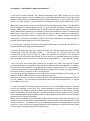
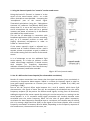
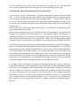
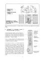
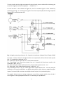
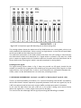
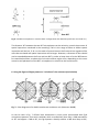
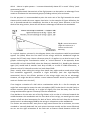
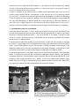
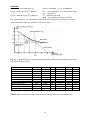
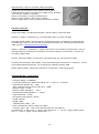
The NEVATON BPT - "Blumlein-Pfanzagl-Triple"
3-capsule Stereo- and
Surround-Microphone with Center-Zoom Function:
ready for 5.1, 7.1 and beyond …
USER MANUAL Vers. 1.3
Ser. # …………………
1
0. Preamble – “Why build a 3 capsule microphone ?”
As the name already indicates, the “Blumlein-Pfanzagl-Triple” (BPT) makes use of a third
figure-of-eight capsule, which is added to the well known Blumlein-Pair of two figure-of-8
capsules, which have an included angle of 90° and are oriented at +/- 45° towards the sound
source. The new capsule is pointed directly towards the middle of the sound source at 0°.
Why add a third capsule at all, as the Blumlein-Pair already captures 360° ? The BlumleinPair arrangement is appreciated by many as ‘very naturally sounding’ (see *Streicher and
Dooley, 1985]), which is attributed also to the fact that the signals of the two channels are
largely decorrelated (meaning: very different) also at low frequencies, which is important for
good spatial impression. This is a unique feature which is almost exclusively reserved to
crossed figure-of-eights (when it comes to ‘one-point’ or closely spaced microphone
techniques), as all other microphone patterns (with hypercardioids as an exception) do not
provide similar signal-separation for low frequencies.
As a one-point recording technique with highly directional microphones the BPT-mic is
characterized by providing precise localization.
Tomlinson Holman described this behaviour, which can also be found with figure-of-eight
microphones, with the following words: „ … The system *i.e. Blumlein-pair] aims the
microphones to the left and right of center; for practical microphones, the frequency
response at 45° off the axis may not be as flat as on axis, so centered sound may not be as
well recorded as sound on the axis of each of the microphones …” (see *Holman, 2000+).
This is of course one of the main reasons why it makes very much (sonic) sense to add a
third figure-of-eight microphone or capsule to the “Blumlein-Pair” arrangement. In addition,
this gives the sound engineer a high degree of freedom, of how broad / (i.e. ‘stereophonic’)
or narrow (‘monophonic’) he would like the sound image to be, by simply varying the level of
the Center-capsule in relation to the L and R capsule.
For normal recording applications, the level of the center microphone will usually be set
between -6 dB to -3dB in relation to the L and R microphone.
Deviations of this are – of course – possible and for some applications it might make sense to
set it at -10dB or – if it is necessary to emphasize the center of the sound-source – it may be
set to 0dB or even more.
In order to shield off unwanted signals from the rear it is preferable to place an acoustic
barrier (for example in the form of a sound-absorptive acoustic panel) behind the BPT
microphone. This helps to achieve a better direct-/diffuse sound (i.e. direct signal /reverb)
ratio and enables the sound engineer to move the system further away from the soundsource thereby usually achieving also a better balance between instruments (or instrumental
groups) in case of larger ensembles.
(Rem.: If the absorptive panel cannot be used for optical reasons, the three capsules of the
microphone can be switched to cardioid pattern and attenuate sound from the rear in this
manner. However – if possible, the use of an absorptive panel is recommended, as this will
result in a much clearer sonic image achieved in the recording, since diffuse sound arriving
from the back is being eliminated more effectively)
2
1. Using the Center-Capsule C to “zoom in” on the sound source
Rising the level of C ‘focuses’ or ‘zooms in’ to the
centre of the sound source, while – as a side
effect, desirable or non-desirable – increasing the
‘monophonic’ part of the overall signal.
Theoretical calculations (using the “Microphone
Assistant V.2” software - see [Wittek, 2002]) have
shown that if C is set at the same level as the L
and R microphone the result will be a gradual
increase and boost of volume by 3 dB towards
the middle of the sound-source.
This can be of advantage in connection with
broadcast-applications (news, location recording,
etc.), as it is common practice to work with
(highly) directional microphones in order to
create an “acoustic focus”.
If the center capsule’s signal is adjusted to a
relative level of -10dB in relation to the L and R
capsule, almost no emphasis or gain is added to
the sounds coming from the centre of the soundsource.
It is of advantage to use the additional fig-8
center-capsule, as it helps to achieve a more
stable sound-image especially if sound sources
with complex (i.e. frequency dependent)
radiation characteristics (as is the case with many
music instruments) need to be recorded.
Fig. 1: BPT-mic (normal mode)
2. Use of a HPF on the Center-Capsule (for enhanced de-correlation)
Results of various researchers have shown that low signal-correlation (cross correlation) is
necessary at frequencies below approx. 200Hz in a stereo (or binaural) signal in order to
have good spatial impression as a listener (see –among others - [Hidaka et al, 1995] and
[Griesinger, 1998]).
Due to the 90° physical offset angle between the L and R capsule, which have fig-8
characteristics, the signal of these two will be completely de-correlated over the entire
frequency response (to be precise: for diffuse sound signals, arriving from all directions).
Adding the signal of the center capsule (by mixing it in on the stereo-bus, or routing it to the
center-speaker in a 5.1 surround setup) signal perception will certainly become more
correlated over the entire frequency band. For the sake of good spatial impression,
correlation for bass-frequencies should be kept at a minimum: the simplest way to achieve
this is by setting a High-Pass-Filter (HPF) on the signal of the Center capsule, with a cut-off
frequency somewhere in-between 90 and 160Hz, depending on the frequency response of
the sound-source, the acoustics of the room, etc.
3
This can be done on the mixing desk, or already while recording by use of the High-Pass
Filter-control (fc=90Hz) on the rear of the BPT-mic set to the position on the right.
3. Choosing the right distance between BPT and sound-source
Concerning the normal “Blumlein-pair” microphone technique Tomlinson Holman stated
that “… The system makes no distinction between front and back of the microphone set, and
thus may have to be placed closer than other coincident types … “. There is certainly a point
to it, as in a normal concert situation the rear lobes of the fig-8 microphones will mainly pick
up reverb from the hall and therefore the direct/diffuse sound ratio will be affected in a
negative way.
If the natural mix of these two signal components is too reverberant, an absorptive panel
should be placed behind the BPT.
When using an absorptive panel, the soundfield of the rear hemisphere is kept away from
the BPT and therefore the critical distance (i.e. reverberation radius; see appendix) is
effectively doubled for the microphone, which means it can be moved away from the soundsource by the amount equivalent to the reverberation radius, while the direct/diffuse sound
ratio will remain the same (due to the addition of the absorptive panel behind the BPT).
A second important factor needs to be considered for the placement of the BPT microphone,
which is the physical opening angle of the L and R fig-8 capsules (angled at +/-45° relative to
the sound source). Even though the Blumlein-Pair is said to have a correct recording angle of
120° (see [Streicher and Dooley, 1985]), it is certainly preferable if the main body of the
sound source stays well within the included angle of 90°, as otherwise there is the danger
that a sound source in front on the far left might be picked up by the rear lobe of the right
fig-8 capsule of the Blumlein Pair and therefore will be replayed not only from the left side
(left capsule signal), but also from the right side, but with a phase inversion.
In [Faulkner, 1981] the question of optimal microphone positioning in order to achieve a
good balance between all instrumental groups of an orchestra in a concert location has been
discussed. As sound engineer Tony Faulkner points out the “old rule of thumb” to position
the main (stereo) microphone at a distance of about half the width of the orchestra away
from the sound-source can be enlarged to the whole width in case of highly directional
microphones, which is the case of fig-8 microphones (and even more so, if an absorptive
panel is used). Therefore a microphone position in the 6th up to the 9th row, as pictured in
fig.2, might not only be “good seat” position for a listener, but also for a Blumlein-Pair or
BPT-mic.…
4
Fig. 2: Microphone position vs. listener position in a concert hall [adapted from Faulkner,
1981]
4.
RECORDING IN SURROUND Version
The BPT in 5.1 mode (see Fig. 3 ->)
1:
As stated by audio engineer Tomlinson Holman “…
Two channel stereo can produce the sensation of
looking into a space beyond the loudspeakers;
multichannel stereo can produce the sensation of
being there ...” [Holman, 2000]
This is a strong statement for making surround
recordings and the BPT makes this quite easy, as
no external processor is needed:
If you want to create a 5.1 surround signal with
just one BPT-mic, the pattern selector needs to be
switched to total left position. In this mode the
top capsule (# 3) is in omni mode (and rotated to
+45°), while capsules #1 and #2 remain in fig-8
mode. As the 5.1 signal is going to be derived by
using MS-decoding, the BPT-mic as a whole needs
to be rotated by 45° so that the lowest capsule
(#1) becomes a figure-8, which picks up sound to
the LEFT and RIGHT of the microphone, while
capsule #2 picks up the FRONT and BACK soundfield.
5
To help visually with the right orientation of the mic-body, there is dashed line indicating the
correct 0° alignment of the microphone: ----FRONT 5.1 ----As can be seen in the scheme of figure 4, the 5.1 surround signal is then created by
combining (mixing, i.e. summing) the signals of the omni-capsule (#3) with the fig-8 capsules
(#1 and 2#) in an appropriate way.
Fig. 4: signal processing schematic for 3-capsule microphone (adapted from [Eargle, 2004])
For the 5.1 “Center-channel” the signal of the omni-capsule (#3, “W”) and front-back capsule
(#2, “X”) need to be combined: W + X
For “Front Left” all the signals W + X +Y need to be summed.
For “Front Right” the same three signals, but on Y (capsule #1) the phase needs to be
reversed by 180°: W + X - Y
For “Rear Left” (also called ‘Left Surround’ or LS) we need to perform: W – X + Y
For “Rear Right” (also called ‘Right Surround’ or RS): W – X - Y
The processing as seen in fig. 4 – which might seem complicated at first – can very easily be
achieved on a normal mixing desk: on digital mixing desks, which allow to assign the signalinput of a channel A/D-converter to multiple channel strips, this is particularly easy.
The graphic below shows a routing assignment on an 8-bus console which mixes the W, X
and Y signals on the appropriate busses for 5.1 recording or reproduction.
6
Fig. 5: BPT-microphone signal MS-decoding on an 8-bus mixing desk
The routing scheme above also makes use of the PAN function on a mixing desk, which is not
really needed if the desk allows “direct routing” to single busses. In that case all input faders
can be set to 0dB and the PAN-control at center.
The -3dB level attenuation on the fader needs to be done if for L/R-routing on stereo-busses
the PAN-control needs to be employed, as a signal which is panned in this way has a 3dB
gain in respect to signals which are routed to both bus-channels with the PAN-control set at
center (due to the ‘panning law’ which is normally employed in mixing desks).
Creating an LFE-signal:
The signal-routing layout shown in fig. 5 does not provide an LFE-signal; should this be
needed, the easiest way to generate one would be to bring up the W (omni) signal on a free
input-channel, then low-pass filter it with a cut-off frequency set somewhere between 90 120Hz, route it to bus #4 and balance it in level wise, according to taste.
5. RECORDING IN SURROUND - Version 2: two BPT’s in “Back-to-back” mode (2 x 3.0)
There is a second possibility to achieve a 5.1 surround recording with the BPT microphone,
which offers better channel separation (especially between front and rear signals) by use of
2 BPT microphones and (at least one) acoustic baffle and absorptive panel in-between.
In this case for both front and rear a BPT-mic in 3.0 mode is being used, which directly
deliver the signals for L, Center, Right (Front) and LS, RS (Rear).
This version has the advantage that no signal-processing (MS-decoding) is needed.
7
Fig. 6: Two BPT microphones in ‘Back-to-back’ configuration with absorber panels (for surround rec.)
The distance “d” between the two BPT microphones can be varied to control the amount of
spatial impression contained in the recording: if d is in the range of 50cm to 100cm spatial
impression will be less, if d is in the order of several meters the front and rear signals will be
more de-correlated and spatial impression will be larger. However, a distance of 10m should
not be exceeded between the front and rear BPT in order to keep time-of-arrival differences
for sound below 30ms, as above this limit echo effects might occur, depending on the room
acoustics and placement of the BPT- microphones in relation to the sound source.
6. Using the Figure-of-Eight pattern to “re-balance” the orchestra (and soloists)
Fig. 7: Polar diagrams of a double membrane condenser mic (Neumann KM88)
As can be seen in fig. 7 off-axis level attenuation is much more pronounced with fig-8
microphone patterns, than with cardioids: while a cardioid will have only 1-2dB attenuation
at 30° and approx. 4 dB at 60°, the fig-8 pattern already exhibits a 9dB level drop at 60°,
8
which - due to its polar pattern – increases dramatically above 60° to reach ‘infinity’ (total
attenuation) at 90°.
This strong directional characteristic of the fig-8 pattern can be used as an advantage if one
needs to re-balance the instrumental groups (including soloists) of an orchestra:
For this purpose it is recommended to point the main axis of the fig-8 towards the sound
element which needs the most support level-wise. In the example of Figure #8 below, the
mic is directed towards the woodwinds, but due to the much closer distance to the first
desks of the sting section, these will still have an advantage of 2dB over the woodwinds.
Fig. 8: vertical attenuation
(angle of incidence) as a
creative tool for level
balancing
In a typical situation, pictured in the diagram above, the microphone could be positioned
approx. 3m (9feet) above the first desks of the strings, while the woodwinds might be
approx. 9m (27 feet) away. Hence a distance ratio of 1:3 applies. As can also be seen in the
graphic concerning the “reverberation radius” or “critical distance” in the appendix, direct
sound suffers a level drop of 6dB, when the distance is doubled (2:1). Doubling the distance
again (4:1) would lead to another level drop of 6dB, so a total of 12dB attenuation; a
distance ratio of 1:3 therefore results in a level drop of 9dB.
[Rem.: usually, when miking the strings from above they might tend to sound rather bright
and sometimes aggressive, therefore a slight level-drop (and also high-frequency
attenuation) due to the off-axis position of the strings might even be an advantage.
However, we might be able to achieve a more balanced overall sound by moving the BPT
main-mic further out in the hall ]
If we imagine a situation of a hall with a reverberation radius Dcrit = 6m for example, we
might feel encouraged to move the main microphone (BPT) further back in the hall (with or
without acoustic panel behind), so it might be slightly less than 6m away from the first
strings and therefore approx. 12m away from the woodwinds.
If we decide to tilt the main axis of the fig-8 down a bit so that it is directed towards the
middle between the woodwinds and the first desks of the strings, we would get the same
amount of off-axis level attenuation for both of them, while the level drop due to distance
would result in an advantage of 6dB for the strings in comparison to the woodwinds.
The further we move the BPT away from a large sound source like an orchestra, the more
rounded or ‘naturally balanced’ the sonic picture becomes usually and the more effectively
we can use the right orientation of the main-axis to feature sound elements within the
9
sound source, who need that kind of support. In the absence of spot-microphones, soloists
in front of the orchestra next to the conductor, or a harp further back in the orchestra might be
the usual candidates which need such help ...
To give an example of the effectiveness of diffuse sound attenuation due to the use of an
acoustic panel behind the BPT microphone: in the concert hall of the Salzburg Festival
(D_crit=5,5m) – in order not to obstruct sight-lines from the balcony - the BPT mic with panel
is 12m (!) away from the conductor’s podium. Since the curved absorptive panel shades off
the rear half-hemisphere of diffuse sound, the critical distance is effectively doubled, so
even with such a large distance to the orchestra, the direct-/diffuse-sound ratio is still a
“healthy” one and provides nice-sounding results for high-quality documentary recordings ...
7. Flat absorptive panel vs. curved panel
As already mentioned above, in many recording situations the final result will benefit from
the use of an absorptive acoustic panel behind the BPT-microphone in order to re-balance
the direct- to diffuse-sound ratio (Rem.: … for use of the BPT in ‘3.0 mode’. If the BPT is used
in the ‘5.1 mode’, of course the rear side should not be covered or shielded off potential
sound sources or diffuse sound).
A curved acoustic panel will usually be more effective, as with the same surface it manages
to ‘protect’ a larger angle of the microphone from picking up unwanted sound. On the other
hand, some focusing effects may be noticed with a curved (rounded) acoustic panel, if the
absorptive materials are not fully absorptive over the whole frequency range (which is hard
to achieve sometimes if its mechanically supportive elements are made of metal).
In practical experiments it has been found that curved absorptive panels, with diameters
useful in connection with the BPT microphone (diameter approx. 40cm), may produce
unwanted reflections (and therefore sound coloration due to comb-filtering effects) in the
frequency band roughly between 500 – 700 Hz. In this case a band-filter tuned to about
600Hz with Q=3 to 5 and an attenuation of -4 to -8dB (inserted on at least the L and R BPTmic signal) will help to eliminate unwanted sound coloration artifacts.
10
APPENDIX:
Definition of “critical distance” Dcrit :
Dcrit [m] = 0.057 sqrt (V [m3] / RT60 [s])
or
Dcrit [ft] = 0.03147 sqrt (V [ft3] / RT60 [s])
with 1ft = 0.3048m or 1m = 3.2808 feet
Dcrit …. “Critical distance” (i.e. reverberation radius)
sqrt …. square root
V …. Volume of the room
RT60 … reverb time of the room in seconds
The “critical distance” (or reverberation radius) from the sound source is reached, when diffuse
sound reaches the same level (volume) as the direct sound.
Fig. 11: “Critical Distance” (D_crit): Relation between SPL and distance to sound source for directand diffuse-sound in a room
Hall
Ottobeuren (church, Germany)
Royal Albert Hall, London
Amsterdam Concertgebouw
Boston Symphony Hall
Vienna Musikverein
Teatro della Scala (opera, Italy)
Eisenstadt Castle - concert-hall
King's Theatre, London
Brahmssaal, Vienna Musikverein
Esterháza Castle - concert hall
control room (typ. rec. studio)
Volume [m3]
Volume [ft3]
Seats
RevTime [s]
D_crit [m] D_crit [ft]
130000
86650
18700
18740
14600
11252
6800
4550
3390
1530
4590300
3059612
660297
661709
515526
397308
240108
160661
119701
54024
n.a.
5080
2206
2631
1680
2289
n.a.
n.a.
604
n.a.
7,00
2,40
2,00
1,80
2,05
1,24
1,70
1,55
1,63
1,20
7,77
10,83
5,51
5,82
4,81
5,43
3,60
3,09
2,60
2,04
25,48
35,53
18,08
19,08
15,78
17,81
11,83
10,13
8,53
6,68
118
4167
n.a.
0,24
1,26
4,15
Table 1: Reverb time and resulting critical distance for performance spaces of different size
11
High Pass Filter Control on rear side of BPT-Microphone:
On the rear side of the BPT a filter-selector can be found:
A High-Pass Filter with corner frequency at 90Hz can be switched
in for all three capsules, if needed.
Switch in left position, all three capsules linear.
Switch in center position: HPF for all 3 capsules
Switch in right position: only top capsule #3 has HPF activated
Literature references:
Eargle, John (2004): „The Microphone Book“, (fourth edition), Focal Press 2004
Faulkner, T. (1981): “A Phased Array”, Hi Fi News Record Rev., pg. 44ff, July 1981
Griesinger, David (1998): ”General Overview of spatial impression, envelopment, localization and
externalization” Proc. 15th Int. Conf AES on Small Room Acoustics, pp. 136-149, Denmark Oct/Nov
1998 (see also: www.word.std.com/~griesngr )
Hidaka, T., Beranek L., and Okano, T. (1995): "Interaural cross-correlation, lateral fraction, and lowand high-frequency sound levels as measures of acoustical quality in concert halls", J. Acoust. Soc.
Am. 98 (2), August 1995
Holman, Tomlinson (2000): “5.1 Surround - Up and Running”, pg. 216, Focal Press, 2000
Streicher, Ron and Dooley, Wes (1985): „Basic Stereo Microphone Perspectives – A Review“ , Journal
of the Audio Eingineering Society, vol. 33, No7/8, pp. 548-556, July/Aug. 1985
Wittek, Helmut (2002): “Microphone Assistant V.2”(Software), www.tonmeister.de
NEVATON BPT-Mic - technical data:
- Frequency Range: 20-20000Hz
- Free Field Sensitivity at 1000Hz and 1000 Ω: 20 +/-2 mV / Pa (or better)
- Equivalent SPL DIN/IEC 651: 5 dB- Max. Sound Pressure Level [for THD 0,5% ]: 142dB
- Dynamic range: 137 dB
- Nominal output impedance: < 50 Ω
- Recommended Load Impedance: >= 1000 Ω
- Capsule diameter: 33 mm
- Microphone body diameter: 48 mm
- Length: 245 mm
- Weight: 808 g
- Phantom power (48V +/- 4V)
- Power consumption: approx. 10mA per capsule
- Connector Type: XLR, 7-pin (male connector built into microphone)
Pin assignment: 1= GND, pin 6+7 = signal „Left Capsule (#1)“ +/-, pin 4+5 = signal „Right capsule
(#2)“ +/-, pin 2+3 = signal „Center capsule (#3)“ +/-
12