1
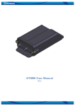
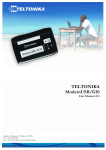
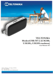
FM2100
USER MANUAL
V1.0
DRAFT
FM2100 User MANUAL v 1.0 PRELIMINAR DRAFT
Table of Contents
ATTENTION!.................................................................................................................................... 2
INSTRUCTIONS OF SAFETY ........................................................................................................ 3
LEGAL NOTICE............................................................................................................................... 4
Short description ................................................................................................................................ 5
1.1
About the document....................................................................................................... 5
1.2
Acronyms....................................................................................................................... 5
1.3
Mounting guidelines ...................................................................................................... 5
2
Package contents........................................................................................................................ 6
3
Main Features............................................................................................................................. 7
4
Mechanical features ................................................................................................................... 8
4.1
Device connectors and dimensions.................................................................................... 9
4.2
FM2100 technical specification....................................................................................... 10
4.2.1
Navigation LED ....................................................................................................... 10
4.2.2
Modem LED ............................................................................................................ 10
4.2.3
Status LED ............................................................................................................... 11
4.3
SIM card insert scheme.................................................................................................... 12
5
Connection & pinout................................................................................................................ 13
5.1
Socket 2×3 ....................................................................................................................... 13
5.2
PORT 1/NMEA ............................................................................................................... 13
6
Changes Log Sheet .................................................................................................................. 14
1
FM2100 User MANUAL v 1.0 PRELIMINAR DRAFT
ATTENTION!
Do not disassemble the device. Do not touch before unplugging
the power supply if the device is damaged, the power supply
cables are not isolated or the isolation is damaged.
All wireless data transferring devices produce interference that
may affect other devices witch are placed nearby.
The device may be connected only by qualified individuals.
The device must be firmly fastened in the predefined location.
The programming must be performed using a second class PC
(with autonomic power supply).
The device is susceptible to water and humidity.
Warning!! May explode, if a wrong accumulator is used.
Any installation and/or handling during a lightning storm is
prohibited.
FM2100 has not USB interface; it has Mini USB connector type
with physical RS232 interface.
Do not plug it to PC’s USB port.
Please use cables provided with FM2100 device.
Teltonika is not responsible for any harm caused by using wrong
cables for PC <-> FM2100 connection.
2
FM2100 User MANUAL v 1.0 PRELIMINAR DRAFT
INSTRUCTIONS OF SAFETY
This chapter contains information on how to operate “FM2100” safely. BY following these
requirements and recommendations you will avoid dangerous situations. You must read these
instructions carefully and follow the strictly before operating the device!
The device uses a 10V...30V DC power supply. The nominal voltage is 24V DC. The allowed
range of voltage is 10V...30V DC, power – not more than 12 W.
To avoid mechanical damage, it is advised to transport the FM2100 device in an impact-proof
package. Before usage, the device should be placed so that its LED indicators are visible, which show
what status of operation the device is in.
When connecting the connection (2x3) cables to the vehicle, the appropriate jumpers of the
power supply of the vehicle should be disconnected.
Before dismounting the device from the vehicle, the (2x3) connection must be disconnected.
The device is designed to mount in a zone of limited access, which is inaccessible
for the operator. All related devices must meet the requirements of standard EN 60950-1.
The device FM2100 is not designed as a navigational device for boats and aircraft.
FM2100 has not USB interface; it has Mini USB connector type with physical RS232
interface.
Do not plug it to PC’s USB port. Please use cables provided with FM2100 device.
Teltonika is not responsible for any harm caused by using wrong cables for PC <->
FM2100 connection.
3
FM2100 User MANUAL v 1.0 PRELIMINAR DRAFT
LEGAL NOTICE
Copyright © 2008 Teltonika
All rights reserved. Reproduction, transfer, distribution or storage of part or all of the contents in
this document in any form without the prior written permission of Teltonika is prohibited.
Other products and company names mentioned herein may be trademarks or trade names of their
respective owners.
4
FM2100 User MANUAL v 1.0 PRELIMINAR DRAFT
SHORT DESCRIPTION
FM2100 is a terminal with GPS and GSM connectivity, which is able to determine the object’s
coordinates and transfer them via the GSM network. This device is perfectly suitable for applications
where location acquirement of remote objects is needed. It is important to mention that FM2100 has
additional inputs and outputs, which let you control and monitor other devices on remote objects.
1.1
About the document
This document contains information about the architecture, possibilities, mechanical
characteristics of the FM2100 device.
1.2
Acronyms
PC – Personal Computer.
GPRS – General Packet Radio Service.
GPS – Global Positioning System.
GSM – Global System for Mobile Communications.
SMS – Short Message Service.
1.3
Mounting guidelines
The device is mounted in the predefined location in the object by attaching it using a two-
sided tape and additionally securing using three plastic 300x4 mm straps. If there is no possibility of
mounting the device in the predefined location as written above, alternative mounting methods may
be applied, securing the stable position of the device.
5
FM2100 User MANUAL v 1.0 PRELIMINAR DRAFT
2 PACKAGE CONTENTS
The FM2100 device is supplied to the customer in a cardboard box containing all the equipment
that is necessary for operation. The package contains:
1. The FM2100 device.
2. Input and output power supply cable with a 2x3 connection.
3. GPS antenna (optional).
4. Port 1 and GPS cables
5. Additional accessories (if ordered)
Note: the manufacturer does not supply a SIM card in the package, which is necessary for connection to the GSM
network! SIM card can be obtained from Your local GSM service provider!
If any of the components is not in the package, please contact the manufacturer’s representative
or the vendor. (www.teltonika.lt)
6
FM2100 User MANUAL v 1.0 PRELIMINAR DRAFT
3 MAIN FEATURES
9 Track your remote objects (trucks, cars) quickly and easily.
9 The device supports the following GSM bearers:
o GPRS class 10 (up to 44,8 kbps).
o SMS (text/data).
9 Quad-band:
o European (and Asian) - 900 MHz / 1800 MHz and American - 850 MHz / 1900 MHz.
9 Case of the device is very robust and perfectly suitable for installation into harsh environment
such as cars, trucks or other moving objects.
9 FM2100 has 2 digital inputs, 2 digital outputs which could be used for performing of various
tasks on remote objects,
9 FM2100 has NMEA output via RS232 that could be used for navigation purposes.
9 3 LED indicators: “Modem”, “Status” and “Navigate”.
9 An advanced solution for a very reasonable price.
7
FM2100 User MANUAL v 1.0 PRELIMINAR DRAFT
4 MECHANICAL FEATURES
8
FM2100 User MANUAL v 1.0 PRELIMINAR DRAFT
4.1
Device connectors and dimensions
All the dimensions in mm, tolerance ±0.5 mm
Figure 1. FM2100 mechanical drawing & spec ,
9
FM2100 User MANUAL v 1.0 PRELIMINAR DRAFT
4.2
FM2100 technical specification
Table 1. FM2100 technical specification
Part name
Navigation LED
STATUS LED
MODEM LED
GPS
Socket 2×3
Physical specification
LED
LED
LED
GPS antenna connector MCX
Tyco Micro MATE-N-LOK 3mm
794617-6
PORT
1/NMEA
Mini USB socket
(RS232 physical layer)
Technical details
Power supply 10...30 V DC
12W Max
Energy consumption:
GPRS:
200 mA r.m.s Max.,
Nominal:
65 mA r.m.s.,
Sleep:
32 mA r.m.s.
Operation temperature:
-25°C ... +55°C
Storage temperature:
-40°C ... +70°C
Storage relative humidity 5 ... 95% (non
condensation)
4.2.1 Navigation LED
When GPS signal is not received, the Navigation LED is switched on permanently.
When GPS signal is received, the Navigation LED is blinking as follows:
When Navigation LED is off, that means GPS antenna or connector is short circuited
4.2.2 Modem LED
When device is connected to the GPRS – Modem LED is blinking every second:
10
FM2100 User MANUAL v 1.0 PRELIMINAR DRAFT
When device is not connected to GPRS – Modem LED is blinking every 5 seconds.
4.2.3 Status LED
When device has uploaded firmware – Status LED should blink. If LED does not blink – it means
that device does not function.
11
FM2100 User MANUAL v 1.0 PRELIMINAR DRAFT
4.3
SIM card insert scheme
c
d
e
f
c
d
e
f
Open the sim holder and insert the SIM card as shown.
Close the sim holder
Push SIM holder’s top part in shown direction to clip SIM holder
Assemble device with enclosure’s top part as shown and screw the bolts.
12
FM2100 User MANUAL v 1.0 PRELIMINAR DRAFT
5 CONNECTION & PINOUT
5.1
Socket 2×3
DIN 2
3
6
OUT 2
DIN 1
2
5
OUT 1
VCC (10÷30)V DC (+)
1
4
GND(VCC(10÷30)V DC)(-)
Figure 2. 2×3 socket pinout
Pin
Nr.
Pin Name
1
2
Description
3
1
VCC (10÷30)V DC
(+)
2
3
DIN 1
DIN 2
4
GND(VCC(10÷30)V
DC)(-)
Power supply for module. Power supply range (10...30) V DC
Energy consumption: GPRS:
200 mA r.m.s Max., Nominal:
65 mA r.m.s..
Digital input, channel 1*
Digital input, channel 2*
Ground pin. (10÷30)V DC ( - )
Digital output. Channel 1. Open collector output. Max.
150mA.
Digital output. Channel 2. Open collector output. Max.
6
OUT 2
150mA.
* - digital input status 0 … ~2 V – FALSE; ~2 V … 30 V– TRUE
5
5.2
OUT 1
PORT 1/NMEA
Mini USB connector
1 2 3 4 5
PORT 1 (RS232)
Pin
Nr.
1
2
3
4
5
Description
GPS TX (NMEA)
RX
TX
GND
FM2100 has not USB interface; it has Mini USB connector type with physical RS232
interface.
Do not plug it to PC’s USB port. Please use cables provided with FM2100 device.
This port can be used as system port (to flash firmware and configuration to device) with cable
“Port1” and as GPS NMEA 0183 output with cable “GPS”.
13
FM2100 User MANUAL v 1.0 PRELIMINAR DRAFT
6 CHANGES LOG SHEET
Nr.
Date
2008 April 10.
New
version
number
1.0
Comments
Preliminar draft release.
14