1
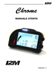
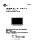
LED dashboard USER MANUAL Version 1.1 Summary 0 INTRODUCTION ...................................................................................................................................................... 2 FEATURES............................................................................................................................................................... 3 BEFORE YOU START ............................................................................................................................................ 3 BOX CONTENT ....................................................................................................................................................... 4 CHROME INSTALLATION ..................................................................................................................................... 5 GPS INSTALLATION .............................................................................................................................................. 6 CHROME INPUTS ................................................................................................................................................... 7 USE OF BUTTONS TO NAVIGATE THROUGH THE MENU.............................................................................. 9 MODIFY NUMBERS OR TEXT............................................................................................................................... 9 STARTUP SCREEN ...............................................................................................................................................10 PLUG&PLAY KIT....................................................................................................................................................10 BASIC SETTINGS ..................................................................................................................................................14 CALCULATE GEAR RATIOS................................................................................................................................15 ADD A NEW CIRCUIT............................................................................................................................................15 EXIT THE STANDBY MODE AND SHUTDOWN.................................................................................................16 SOFTWARE AND FIRMWARE UPDATE.............................................................................................................16 1. MAIN MENU ........................................................................................................................................................17 2. CHRONOMETER................................................................................................................................................17 3. VIEW LAP TIMES ...............................................................................................................................................17 4. DELETE LAP TIMES..........................................................................................................................................18 5. CHOICE OF THE CIRCUIT................................................................................................................................18 6. CIRCUIT DETAIL................................................................................................................................................18 7. DAILY DETAILS ...............................................................................................................................................189 8. EXPORT/IMPORT ..............................................................................................................................................20 9. CIRCUITS LIBRARY MANAGEMENT .............................................................................................................20 10. DISPLAY VIEW.................................................................................................................................................20 11. DATA ACQUISITION .......................................................................................................................................21 12. DOWNLOAD .....................................................................................................................................................21 13. COUNTERS ......................................................................................................................................................22 14. ANALOG AND DIGITAL INPUTS AND GEARS ...........................................................................................22 15. INPUTS SETTINGS..........................................................................................................................................18 16. AUTO CALIBRATION ......................................................................................................................................23 17. CARBURETION ANALYSIS............................................................................................................................24 18. ALARMS MANAGEMENT ...............................................................................................................................24 19. OPTIONS...........................................................................................................................................................25 QUICK GUIDE .....................................................................................................................................................26 1 Introduction The Chrome dashboard represents a real innovation in the aftermarket motorcycle dashboard field. Thanks to the combination of a 800 x 480 color display and a 400 MHz processor, Chrome is able to provide total flexibility to the designer and therefore to the end user. This new technology allows to design a suitable main screen for “STREET” or “RACE” use, leaving the proper amount of space for each indicator. The use of a color display also allows to monitor light warnings like battery problems, lack of gasoline or oil or the amount of remaining fuel. In addition this new dashboard enables to create easy and intuitive menus with a great amount of information. The display has been chosen by I2M to provide a perfect visibility in case of strong direct light too, while a special glass, treated with an anti-reflective coating, eliminates the unpleasant sunlight reflection. For an immediate reading, Chrome has 12 fully configurable ultra-high brightness LEDs, so it is possible to choose the preferred alarm configuration, either related to the RPMs (such as the classic top bar) or, for example, to a dangerously low tire temperature. An aluminum case and a gear indicator, composed of a self-controlled brightness seven segments display, complete the appearance of this new dashboard. Chrome combines dashboard, chronometer, and data acquisition functions. Using the menu it is possible to choose between 20 pre-stored circuits (that can be changed with simple export/import functions through a USB flash drive). Up to 500 laps can be stored for each circuit and each lap can be divided into three different parts (splits). For each circuit the system calculates and shows information such as the map, the best lap, the number of performed laps and the ideal lap, keeping two different historical databases for the current and the previous sessions so that the user can quickly check the trend of the day. Thanks to the graphic display Chrome shows the map directly on the screen so that the user can change the finish line and split positions just moving the cursor across the map. Chrome allows to acquire position and speed data using a 10 Hz GPS but also to read the RPMs, the front and rear speed and 8 external analog channels. Data acquisition allows the user to record up to 1 GB of data and the sampling rate up to 100 Hz per channel can satisfy any request. A practical menu enables to select the desired sessions, ordered by circuit and date and to delete or transfer them to a USB flash drive for analysis through the Danas PC software, thus drastically reducing the download time. The system has two different configurations named “STREET” and “RACE”; for each one it is possible to decide the RPM scale, what has to be shown (speed or temperature) in large font next to the RPM indicator, what has to be shown in each part of the screen [possible choices are: analog and digital channels, times, best lap and ideal lap and the spread between the latter and the actual time (so the user always knows if his time is worse or better than the best lap)]. It is also possible to choose to not display anything in a specific part of the display, in order to reduce distractions when riding. If the system is in “STREET” mode, “RACE” mode will be automatically set as soon as the finish line is crossed, then “STREET” configuration will be activated again at the end of the session. 2 Features 800x480 color display High visibility even under direct sunlight 400 MHz processor with 1GB of internal memory Aluminum case Fully configurable in two operating modes (STREET/RACE) Path and speed detection through 10Hz GPS receiver with 66 parallel channels Chronometer function with 20 pre-stored circuit (up to 500 laps can be stored for each circuit) Automatic circuit detection, with three splits Best lap and ideal lap calculations, all time best and daily lap times Easy-to-use and intuitive interface 12 fully-configurable high-brightness LED alarms 8 10-bit analog inputs 2 independent speed inputs 1 RPM input Separated inputs for water, fuel and oil, each one with a dedicated alarm Gear calculation with automatic-learning function Data download through a USB flash drive Possible connection to a two-button remote control CAN BUS compatible 1GB internal memory 3 different covered-distance counters, 2 engine-time counters and 1 total-performed-lap counter Compact design and small dimensions (172mm x 106mm x 22mm) Waterproof BEFORE YOU START Read carefully the instructions before starting to use the system. A copy of this user manual can be downloaded from the alpha Racing Online shop – LED dashboard. Install Chrome on your bike following the directions reported in the dedicated area. ATTENTION: Chrome has been designed only motorsport racetracks use, and it is not homologated for street use. ATTENTION: Since Chrome is based on the GPS technology, it needs an adequate GPS signal to work properly as chronometer and data acquisition device. For this reason, it is suggested to turn on the GPS receiver some minutes before starting to race, in order to properly receive the signal of the GPS satellites. If the circuit is one of those stored in memory, Chrome will automatically find the position, so it will not be necessary to manually set it. 3 Box content In the Chrome box you will find: - Chrome dashboard 10 Hz GPS receiver standard wire harness with GPS input and USB output (additional plug&play board, if included) connectorized cables for 5V and 12V power supply shell rubber strap with moisture protection user manual The Chrome box content is shown in Figure 1. If the plug&play kit is not included, we advise to solder signal cables and to insulate them. In fact, while Quick Slide or T-Taps connectors are fast and easy ways to join cables, on the long run the connection can fail due to vibrations or tarnishing. Fig. 1 - Box content (demonstrative image only) 4 Chrome installation The Chrome box includes a dedicated wire harness that allows to connect the dashboard to the GPS receiver, to the battery power and to the main sensors on the bike. First of all, connect the power supply to the battery without removing the fuse. The two black cables, carrying the ground reference, have to be connected directly to the battery. Connect the main connector of the wire harness to Chrome. The wire harness, on its other side, provides connectors for the USB flash drive (use only the FAT32 formatting), the GPS receiver and the input signal for external buttons. Connector A (shown in the picture) can be connected either to the generic wire harness B or to a plug&play board. When the latter is chosen, the original wire harness of the bike has to be connected to the other side of the plug&play board. If the generic wire harness is used, it is possible to manually connect the cables corresponding to water, oil, fuel and neutral sensors, RPMs and key-on voltage. Cables are labeled in order to avoid wrong signal connection (see the table below). The acquisition cable can be used to connect the different inputs to the Chrome rear connector (see the pinout scheme below) and to the CAN BUS if included (2-pin AMP connector). 5 All the inputs can be checked using the “Real time inputs view” option in the “Analog and digital inputs” menu. The first screen will show the real time value of the 8 analog inputs, speed 1, speed 2 and the RPM. Keep the DN button pressed to open the subsequent screen where the values of the voltage battery, of the water, of the oil and of the fuel are shown. Battery and water values are reported before and after elaboration (from 0 to 1023 in the first case). The converted values depend on the selected type of bike. If the generic harness is used please remember that each signal can require a pull-up resistor (connected to 12V) or a pull-down resistor (connected to ground) to be correctly read. Neutral and oil signals often require a pull-up resistor (a value equal to 2kOhm is usually enough). Do not tightly bind Chrome to those parts of the bike that are affected by vibrations, like the bike frame. Please use anti-vibrating mounts for the Chrome installation. Chrome includes some antivibrating pawl but also the original anchor systems should be used. For some type of bikes, dedicated anti-vibrating brackets are available to place Chrome in the original brackets. An improper installation will cause a continuous exposure to vibration that can damage Chrome in a very short time, leading to sporadic malfunctions. A rubber cover, to protect the connector, is included in the Chrome box. The cables have to be inserted in the cover that has to be fixed to the Chrome backside flange (use the included clamp). An adhesive tape can be used to fix all the cables and the rubber cover, this way the Chrome is protected from water and moisture. GPS installation In order to receive the best GPS signal, the GPS receiver must be positioned horizontally so that most of the sky is within the receiver field of view. Do not place any metal object near the receiver, since it could shield the satellite signals. Please attach the GPS receiver to the bike with a doublesided adhesive Velcro, thus avoiding a tight bound between the receiver and the bike. ATTENTION: The high operating frequency of the Chrome dashboard can significantly reduce the sensitivity of the GPS receiver, do not place the GPS receiver on or near the equipment. If possible, avoid even the steering plate. The ideal position is on the tail with the appropriate extension. The receiver can also be placed, always horizontal, inside the hulls verified that they are not carbon fiber, a material that would shield the signal. 6 Chrome inputs Two multilock connectors, having 16 pins and 20 pins respectively, are placed on the backside of Chrome. For each connector, the pinout scheme and the pin description are shown in the pictures below. Rear view (cables side) of the 20 pin connector Rear view (cables side) of the 16 pin connector 20-pin connector 16-pin connector 1. Speed 2 (green cable) 1. 12V power supply directly from battery 3. 12V out (orange cable) 2. Fuel (yellow cable) 4. Analog1 3. 12V key-on voltage (orange cable) 6. Analog2 4. Oil (black/white cable) 8. Analog3 5. Battery ground 9. CAN low 6. Water temperature (blue cable) 10. Analog4 7. Battery ground 11. CAN high 8. Neutral (grey cable) 12. Analog5 9. Button1 14. Analog6 11. Button2 16. Analog7 13. RPM (green cable) 18. Analog8 15. Speed1 (white cable) 20. 5V out (red cable) The 16-pin connector is also connected to the PS2 input that is dedicated to the GPS receiver and to the USB connector. Chrome works with a dual power supply: one is directly connected to the battery, while the other is connected to the key-on voltage. Once the system is turned off, none of the two power supplies adsorbs any current. The power supply directly connected to the battery allows Chrome to properly save the files during shutdown and also to keep the correct date and time. DO NOT change the Chrome power supply scheme. Chrome is designed with versatility in mind, so it can work even with no sensors connected and with the GPS receiver kept inactive. 7 Chrome includes the following connections: - 8 analog inputs - 2 speed inputs - 1 RPM input - 1 water temperature input (with a dedicated warning light that turns on when the temperature exceeds 110°C) - 1 oil level input (with a dedicated warning light) - 1 fuel level input (with a dedicated warning light) - 1 battery input (with a dedicated warning light that turns on when the battery voltage drops below 12.5V) - 5V output for powering analog sensors that are not powered by the bike - 12V output for powering digital sensors that are not powered by the bike - GPS channels ATTENTION: The 5V out and 12V out power supplies can be used to power any additional sensor that is not directly powered by the bike. DO NOT CONNECT the “5V out” or the “12V out” to any power supply provided by the bike or to any sensor that is already powered. ATTENTION: Ensure that the 5V and 12V power supply does not create a short-circuit or become shorted to ground, this could indeed damage them beyond repair leading to incorrect readings of the analog inputs. Analog 1-8: these are 10-bit, 0-5 V analog inputs, to be connected to various sensors such as throttle position, brake pressure, tire temperature, suspensions, etc... RPM: this input is specifically intended to record the engine RPMs, obtainable by tapping into the signal sent by the junction box to the dashboard. Attention: the number of pulses for each engine turn varies from bike to bike and MUST BE CONFIGURED in the dedicated menu. The system is able to receive signals up to 20V from the RPM input. Speed: connect these inputs, for example, to the speed sensors on each wheel. These can be adhoc inductive sensors or, for the rear wheel, the signal can be taken directly from a factorymounted sensor that counts the RPMs of the pinion or, in some cases, of an internal shaft directly connected to the pinion. Warning: the number of pulses for each turn varies from bike to bike and MUST BE CONFIGURED in the dedicated menu. Water temperature: 0-5V input used to read the water temperature. The system has been preconfigured for some standard sensors. 12V is the maximum voltage for this input. Oil-level: 0-5 V input used as alarm of the oil level. The alarm level must be configured in the dedicated “alarms management” menu. 12V is the maximum voltage for this input. Fuel-level: 0-5 V input used as alarm of the fuel level. The alarm level must be configured in the dedicated “alarms management” menu. 12V is the maximum voltage for this input. 8 ATTENTION: When the original dashboard is removed from the bike, some pull-up resistors can be removed too; these resistors are usually needed to read sensors like oil or fuel levels. If a plug&play wire harness is not used, check that the available signal is valid after the dashboard removal, otherwise the use of proper pull-up resistors is needed. Use of buttons to navigate through the menu Chrome provides two buttons that can be externally replicated through the dedicated connector. UP BUTTON: allows to navigate in the menu selecting the upper entry. If the button is pressed in the startup screen, the “view lap times” menu is directly shown. DN BUTTON: allows to navigate in the menu selecting the lower voices. If the button is pressed in the startup screen, the main menu is directly shown. ENTER A MENU: keep DN button pressed to enter a menu or to modify a parameter. EXIT FROM A MENU: keep UP button pressed to exit from a menu or from a parameter modification. Press and hold down the UP button on the main screen to access the quick menu and to reset any suspension potentiometers connected to analog channels (2 and 3). Press and hold down the DN button on the main screen to make a direct download on USB key of the current day data. Modify numbers or text As will be shown in the following, it is possible to give a name to a particular input or circuit, or to set a numeric value for some parameters. The procedure will be explained in details in the following paragraphs. In all these cases it is possible to modify the name or the number by changing each character. UP and DN buttons are used to change the character value. Keep DN button pressed to access the adjacent character; keep UP button pressed to exit from the selection. 9 Startup screen When Chrome is turned on, the startup screen is shown (see the figure below). The GPS indicator, in upper-left corner, is visible (about 4 seconds after the screen appearance) if the GPS receiver is connected. If the indicator is not visible, please check the connection. When the GPS indicator is red, it means that the GPS receiver is connected but a valid position has not been found yet. As soon as the GPS signal becomes valid, the indicator will show the signal power through a bar diagram. “Rec” message appears below the GPS indicator when the system is recording data. The tachometer limits and all the other items shown in the startup screen can be fully configured. The speed gauge, placed in the upper-right corner, can be configured to show alternatively the temperature (see the “display view” section). Plug&Play Kit If your bike is included in the list of motorcycles for which a Plug & Play harness is available, the Chrome will be provided with the appropriate additional board. All the kits are simply made of a board that allows to connect the wiring of the Chrome directly to the connector of the original dashboard (except for the BMW S1000RR). 10 Installing a Plug & Play kit is extremely simple, it is sufficient to connect the additional board and load the settings related to your bike. Additional board The additional board is typically a simple board to adapt the wiring of Chrome and the one of the original dashboard. In the cases listed below, the additional board also includes other connections: - - - - - Yamaha: the board also includes a male/female connector that has to be connected in series to the original speed sensor connector and a blue cable that has to be connected to the water temperature sensor. The latter comprises two wires, one connected to the ground, connect the blue cable to the other terminal (it is necessary to identify the wire connected to the ground with a tester). Suzuki: the board also includes a blue wire that has to be connected to the temperature sensor water of the bike. The latter comprises two wires, one connected to the ground, connect the blue cable to the other terminal (it is necessary to identify the wire connected to the ground with a tester). Ducati 1198: the board also provides a CAN BUS connection, the CAN BUS board connector (2-pin AMP) must be connected to the corresponding CAN BUS pins in the 20pin Chrome connector. KAWASAKI ZX10R >2010: the board also provides a CAN BUS connection, the CAN BUS board connector (2-pin AMP) must be connected to the corresponding CAN BUS pins in the 20-pin Chrome connector. BMW S1000RR <2011: the Plug & Play harness for BMW is different from the previous ones and provides an additional wiring. The additional wiring has to be connected to the DWA connector in the motorcycle tail and to the fuel level sensor under the tank (replacing the original). The other side of the Plug & Play harness has to be connected to Chrome to the corresponding CAN BUS pins in the 20-pin Chrome connector. Therefore it is necessary to make a jumper in the white connector pin 1 and 2 (see pic a) to enable the power on. In order to enable the ABS/TC button on the left block, which is the only one working in “RACE” configuration, it is necessary to restore its ground connection making a second jumper between the white connector pin 6 and the black connector pin 1 (see pic b). (a) (b) 11 - BMW S1000RR >2012 and HP4: the Plug & Play harness for BMW is different from the previous ones and provides an additional wiring. The additional wiring has to be connected to the DWA connector in the motorcycle tail and to the fuel level sensor under the tank (replacing the original). The other side of the Plug & Play harness has to be connected to Chrome to the corresponding CAN BUS pins in the 20-pin Chrome connector. Therefore it is necessary to make a jumper in the white connector pin 1 and 2 (see pic a on previous page) to enable the power on. In order to enable the ABS/TC button on the left block, which is the only one working in “RACE” configuration, it is necessary to restore its ground connection making a second jumper between the white connector pin 6 and the black connector pin 7 (as shown in pic c). (c) Setting load After the electrical connection it is necessary to load the related settings. Use the “Analog and digital inputs” menu, select “configure inputs” and choose “automatic configuration”. In the first row choose “kind of bike” among the possible choices. Select your type of bike; choose your specific model (if listed) otherwise set the brand (for Kawasaki ZX 10R> 2010 Kawasaki select Kawasaki CAN BUS). If the model of your bike is not listed and the related settings have not been preloaded, it is necessary to import the settings through a USB key. In order to accomplish this task take an empty USB key, make sure that the key formatting is FAT32, then copy in the USB key the file ChromeSettings.cfg of your bike model. Connect the USB key to the USB input of the Chrome and select "Import settings from USB" in the "Analog and digital inputs" menu. Ducati 1198 / Kawasaki ZX 10R / BMW S1000RR settings When the settings for Ducati 1198, Kawasaki ZX10R >2010 and BMW S1000RR are loaded, also additional functions will be imported. Ducati 1198 In the case of Ducati 1198, the “Real time” menu in the “analog and digital inputs” menu is changed to “Real-time input & diagnosis”. By entering this menu, the page of the analog inputs can 12 be seen, keep pressed the UP button to switch to the second page where other low level inputs such as water, gasoline and battery are present. Keep the DN button pressed to enter the screen dedicated to Ducati. At the top, the string present in the original junction box (with the name of the bike) is shown, if present it will be possible to enable the DDA and DQS; whereas in the bottom of the page the number of errors is indicated. By selecting "error code" is then possible to scroll them to read their explicit description. The Chrome configured in Ducati 1198 mode automatically acquires on channel 1 the value of the TPS from the CAN BUS. The red LED above the gear indicator takes two distinct functions: on indicates a fault in the junction box whereas flashing identifies the intervention of the TC. The level of TC can be set also in motion and the last level is retained in memory. Kawasaki ZX10R /ZX10R Race>2010 In the case of Kawasaki ZX10R> 2010 the “Real time” menu in the “analog and digital inputs” menu is changed to “Real-time input & diagnosis”. By entering this menu, the page of the analog inputs can be seen, keep pressed the UP button to switch to the second page where other low level inputs such as water, gasoline and battery are present. Keep the DN button pressed to enter the screen dedicated to Kawasaki. In this screen the sequence of the errors in the junction box is present. Errors are encoded with the error code and the original name on the workshop manual. The Chrome configured in Kawasaki ZX10R> 2010 mode automatically acquires on channel 1 the TPS value from the CAN BUS and on channel 8 the level of intervention of the TC (7 levels). The red LED above the gear indicator takes two distinct functions: on indicates a fault in the junction box whereas flashing identifies the intervention of the TC. In the “RACE” mode (to be used with race junction boxes) the front wheel speed is also acquired and the last settings of the power maps and TC are held in memory. BMW S1000RR By setting Chrome in BMW S1000RR mode, the first two red LEDs in the upper right acquire the functions of ABS and TC in exactly the same order and with the same modalities of the original instrumentation. The TPS value on the CAN BUS is shown and acquired on channel 1 whereas the red LED above the gear indicator assumes the meaning of general error. In addition to the RPMs, to the speed of the rear wheel and to the TPS, in the case of BMW S1000RR, the speed of the front wheel is acquired. 13 BMW HP4 By setting Chrome in BMW HP4 mode, the first two red LEDs in the upper right acquire the functions of ABS and TC with the same modalities of the original instrumentation. The TPS value on the Can-Bus is shown and acquired on channel 1 whereas the red LED above the gear indicator assumes the meaning of general error. In the input menu a new page, allowing to configure the parameters of the HP4 suspensions as well as to perform the calibration of the suspensions, appears. As with the original dashboard the launch control functions are still present. In addition to the RPMs, to the speed of the rear wheel and to the TPS, in the case of BMW S1000RR also the speed of the front wheel and the position of the front and rear potentiometers are acquired. BMW S1000RR HL This configuration is the same as the S1000RR one but allows to display the set value of the TC. It should be used only with suitably programmed junction boxes. Basic settings After the installation of Chrome, the instrument can be customized. The first step is to verify that the correct settings for the bike has been installed as explained in the Plug&Play kit paragraph. After uploading the bike settings, configure the inputs on the data acquisition connector (if used). Please refer to the following section for the configuration of the inputs, as a first step put the name of each channel in the “input configuration” menu of and then configure the maximum and minimum values of each channel selecting the manual mode or automatic mode. After configuring the inputs, go into the “display view” menu and choose what to display in the main screen in “STREET” mode and “RACE” mode. As a final step, configure the LED lights through the “alarms” menu. Use this menu to configure each LED. The white LEDs in the upper part of the Chrome can be quickly configured as RPM LEDs in simple steps. Turning on the “RPM” mode from the alarm management page, Chrome will automatically configure the 7 white LEDs so that they are lit throughout the RPM range set in the display view menu. What is recommended to do is: - Set in “display view” the RPM ranges for which the LEDs shall light up - Go to the “alarms” menu and disable and re-enable the RPM mode (the setting takes place only in the transition from off to on) - Return to the “display view” menu and set the preferred RPM range for the view From the “alarms” menu the overrun function can be activated. By activating this function, all the LEDs configured for the RPMs will blink if the last RPM LED threshold is exceeded. This way the overrun flash can be set by simply changing the threshold of the last RPM LED. 14 Calculate gears ratio Follow this simple procedure to configure the gears on your Chrome: - Check that speed and RPM inputs have been already configured correctly - In the “data acquisition” menu, set the following parameters for the acquisition: ACTIVE, 100Hz, autostart channel on “SPD1” and speed equal to 20km/h - Turn on your bike, then change gears keeping each one for at least 10s and making sure that the “rec” text appears below the GPS indicator - Turn off your bike, then select the “calculate gears ratio” option from the “analog and digital inputs” menu - Configure again the data acquisition as you like Chrome calculates gears referring to the sessions of the day. Therefore the procedure can be performed even simply driving the bike in the street or in the circuit, taking care that all the gears are engaged and executing all the calculations in the same place and day when data have been collected (Chrome checks both place and day). Add a new circuit If a new circuit shall be added, two different paths can be followed: 1) update the entire library using Danas 2) modify a circuit on the track Update the library through Danas To update the library, open Danas, go to the "Online" menu and select "Configure Chrome circuits”. From the left list choose 20 circuits and add them using the "+" button. Ended the choice, create the file using the enter arrow button. Move the CircuitiInOut.ccr file to an empty USB key (FAT or FAT32 formatting). Connect the USB key to Chrome and import circuits using the appropriate command in the import submenu into the “Chronometer” menu. WARNING: The selected circuits must be EXACTLY 20. Edit a circuit on the track Follow these steps: - In the “Chronometer” menu, choose “select circuit” to open the “circuits” menu, then select a circuit (keeping DN button pressed) that is FREE or a circuit that can be replaced - In the “circuit details” menu choose “update name” to set the name of the circuit - Change the finish line position by putting it in "absent" - To manually choose the finish line position, select “update finish line position” and set “UPDATE”, then press a button in the position corresponding to the desired finish line; otherwise set “AUTO” to use the automatic configuration - If “AUTO” is chosen, the system will set the finish line position when the 150km/h speed is exceeded, then it will start to measure the lap time 15 - Once the session is finished (the lap times are stored anyway), the user can move the finish line or the splits where he likes by setting “MAP” in the “update finish line position” option Exit the standby mode and shutdown If a standby time has been set, Chrome turns off the display and some peripherals (not the GPS) in order to reduce power consumption; the system will automatically turn off after the set standby time has elapsed. If you want to turn off Chrome before the standby time has elapsed: - Turn off Chrome Wait until the LED in the bottom-right corner flashes Press DN button until the red LED above the gears indicator turns on Release DN button After some seconds the upper white LEDs will flash, this means that the Chrome has been turned off Software and firmware update As a first step, check if the update is necessary: - Go into the menu and then on the “Options” menu - Check if the versions of firmware and software coincide with those present on the website (concerning the firmware version, consider the number before the hyphen: "114-7" indicates the version 114). Once determined that an update is required, proceed as follows: - Use an empty USB key, FAT, FAT32 or NTFS formatting (do not use exFAT formatting) - Download on a pc the required firmware or software upgrade (only an upgrade at a time can be done) - Unzip the file and extract the file "Cruscotto_06" or "firmwareUpdate.hex" (depending on the type of update) and copy it to the USB key - Insert the key in Chrome - Enter the menu and then the “Options” menu - Launch the update - Wait for the completion of the update: attention, remove the power supply in this phase could make the dashboard unusable - Set a stand-by time of 0 hours (if it was set otherwise) in the “Options” menu - Turn off the chrome waiting until it is completely turned off - Restart, verifying in the “Options” menu if the update was successful If necessary to carry out both updates, start with the firmware update, then delete the key and proceed with the software upgrade, in both cases according to the above instructions. 16 1. Main menu Press the DN button from the startup screen to open the Chrome main menu. This menu includes the main system functions, in particular: the chronometer, the settings of the items displayed on the screen, data acquisiti acquisition, the counters, the input configuration, the alarms and the generic options. Keep pressed the DN button to select one of these options. Keeping the UP button pressed, the startup screen will appear again. 2. Chronometer Chrome includes a GPS chronometer with a resolution of 1/100s, based on a 10Hz MTK GPS processor with 66 parallel channels. During the power on, once acquired the GPS signal, the system identifies where it is located and, among the 20 stored circuits, it looks for the coordinates of the finish inish line on the corresponding circuit. If the coordinates don't match with any of the stored circuits, the message "circuit not found" will appear on the startup screen screen. ATTENTION: the circuit search is performed only during the power on. If the dashboa dashboard is turned on before reaching the circuit, the user has to restart it or to manually set the circuit. Thanks to the "Chronometer" hronometer" menu it is possible to display the lap times, erase them and configure all the chronometer options. As for the other menus, keep the DN button pressed to enter the submenu of the selected choice, or keep the UP button pressed to return to the previous menu. 3. View lap times It is possible to display the stored lap times from the “Chronometer” hronometer” menu by keeping the DN button pressed or by pressing the UP button from the startup screen. The lap times performed in the selected circuit are shown in this menu (if no circuit is selected a blank screen appears). Lap times are automatically divided by sessions and each session lists the date and the starting time of the session itself. The displayed lap times are divided into three columns, corresponding to the three 17 split sectors of each lap, and for each lap the best speed is reported. The all-time time best lap and ideal time for the current curre circuit are shown in n the lower part of the screen. ATTENTION: If the position of the split times on the map is changed, changed, the previously stored lap times still remain referred to the old position. ATTENTION: The best and ideal lap displayed in the lower part part of the screen refers to the selected circuit and not only to the shown times. As will be discussed in the section that describes the cancellation, it is possible to delete lap times leaving the best and ideal lap stored, or vice versa. In both cases, itt would be reasonable to have no more correspondence between the all all-time best lap and the best lap in the list. 4. Delete lap times The “Delete”” menu allows to select which information has to be deleted. Indeed, it is possible to delete only the best time relative to the selected circuit, or the list of times, the ideal time or all the times stored in the memory. Keep the DN button pressed to select an option, then follow the instructions on the screen to confirm the cancellation. 5. Choice of the circuit The “Circuits”” menu shows the list of the circuits stored inside Chrome. Chrome is able to store up to 20 different circuits. For each one the best lap, the number of stored laps and the higher speed are collected in a table table. Thanks to the automatic atic identification of the circuit, Chrome recognizes the circuit where it is located. Using this menu it is also possible to choose a different circuit. Press the UP and DN buttons to scroll through the circuit circuits, keep the DN button pressed to select the circuit, c keep the UP button pressed to return to the previous menu. 6. Circuit detail In the “Circuit ircuit detail” menu the information about the loaded circuit is reported. In this menu the number of stored laps, bestt and ideal lap times and highest speed are shown. hown. 18 The maps, which are automatically generated by the system, are displayed on the left part of the screen. If there is no corresponding map stored in the memory, Chrome starts to draw the map the first time the finish line is crossed and it stops when the finish line is crossed again. If the lap is not completed, the map will not be saved. It is possible to remove the auto generated maps selecting the “remove map” function. The configurable parameters for the circuit are shown in the lower part of the screen. The name of the circuit can be changed using the first line: this option makes possible to modify each letter of the name. Keep the DN button pressed to switch character, press the UP and DN buttons to scroll through the letters and keep the UP button pressed to exit. The finish line and splits can be set by using the three subsequent entries. It is possible to select one of these options to manually set the finish line (in this case the finish line has to be crossed without stopping) or, if the map is available, to set the finish line or the splits by choosing the desired position on the map. Indeed, it is possible to move the cursor, through the map, using the UP and DN buttons until the desired position. The “Auto” option automatically sets the finish line when the 150 Km/h speed is exceeded. The first split can be set only if the finish line was stored. Similarly, the second split can be set only if the first split was stored. 7. Daily details The “Daily details” menu summarizes the current day performance. Therefore, it is possible to analyze the number of performed laps, the highest speed, the best and ideal laps and the spread between the latter and the all-time best and ideal laps. 19 8. Export/Import Thanks to this menu it is possible to manage the downloading/uploading of data collected during the chronometer function. It is possible to download the stored circuits by using a USB flash drive in order to save the new finish line in a file compatible with Danas. Similarly it is possible to load a circuit list by using a USB flash drive, replacing the circuits stored in Chrome. The file must be generated by selecting the proper option in the Danas software and then transferred using a USB flash drive. Choosing “export lap times to USB”, a .txt file, including the total and split lap times and the highest speeds, all organized in sessions, is generated. 9. Circuits library management Through the “Circuits library” menu each of the 20 circuits stored in memory can be changed. Simply choose the circuit to change in the first row. The new circuit voice allows to choose which circuit shall replace the current one. The circuit will be chosen among those in the library. The latter can be extended by simply importing it from a USB key. It is possible to download directly the update file from the download area of the website. 10. Display view Thanks to this menu it is possible to set the items displayed in the startup screen. Chrome has two different configurations: “STREET” and “RACE”. For both configurations it is possible to choose several parameters that the system will store in memory. If the system is in “STREET” mode, “RACE” mode will be automatically set as soon as the finish line is crossed, then “STREET” configuration will be on again at the end of the session. If the "Change with VEL1" is set, the transition will occur even when 60km/h are exceeded on the rear wheel. 20 Choose the preferred mode in the first line and all the possible options will be di displayed in the subsequent lines. In the upper right part of the startup screen (the position occupied by the speedometer) it is possible to place the rear wheel speed, the GPS measured speed or the coolant temperature. The speed can be visualized in Km/h scale s or in mph scale. The “RPM” option is used to set the full scale range and the minimum value of the tachometer, these two values are independently configurable to adapt Chrome to different motorcycles or simply to personalize lize the displayed information. The background color option allows to choose from three different background colors: standard, red and green. The last four options identify the four positions on the Chrome startup screen: by selecting one of them, the corresponding position on the screen screen will be highlighted, this way it is possible to choose what has to be displayed in each position. Moreover, each position can be left empty, in order to simplify the screen. The first position is the only one that can show the water temperature, that wil will be displayed together with the corresponding symbol. 11. Data acquisition Chrome features a data sampling acquisition rate up to 100 Hz per channel. Using the “data acquisition” menu it is possible to enable the recording option. The second line shows tthe occupied memory (in %). The sampling rate can be cho chosen through the subsequent line. If a high sampling rate is not necessary, it is recommended to not set values above 20 Hz to not overload the subsequent data analysis. The next two options allow to choose c when the system has to start the recording. Use the “Autostart channel” to choose between the rear wheel speed or the GPS speed, then the system will start to record when the speed will exceed the value set in “Lower “ ower speed”. Using the “Download” menu it is possible to save the data on a USB flash drive or to erase the memory. 12. Download The “download” menu shows all the files stored in the Chrome memory. Files are arranged by date and circuit. The date, the name of the circuit (if it can be identif identified by Chrome) and the file dimension are reported in n the table table, so that it is possible to choose which files have to be downloaded or deleted. Keeping the DN button pressed, it is possible to select a file that will appear 21 next to the “selected file” message. A specific menu can be opened by keeping the DN button pressed again: through this menu it is possible to save the file in a USB flash drive or to delete it, or save or delete all the files. Downloaded files can be opened with Danas, moreover, in the same folder a specific file will be stored to save all the settings. For further information, please refer to the Danas user manual. 13. Counters Chrome features three different covered-distance counters, two time-of-engine counters and a total of performed laps counter. Choose a counter and keep the DN button pressed to erase that value. 14. Analog and digital inputs and gears Through this menu it is possible to configure all the Chrome inputs. Use "configure inputs" to manually set each analog and digital input and use "automatic configuration (analogs)" to set the most common sensors for the analog inputs. "Calculate gears ratio" allows to calculate the gears. The latter are calculated by using the ratio between "speed 1" (which should be placed on the rear wheel) and the RPMs. Both inputs must be correctly configured before proceeding with the computation. The system will calculate the gears with the data that will be acquired during the day on the selected circuit. ATTENTION: do not change the circuit between the acquisition and the calculation. Therefore, it is necessary to start the data acquisition and record a session that includes all the gears for at least 10s each (see the appropriate section). It is possible to check if the chosen settings are correct looking at the “real time” menu. Entering the page of the “Real Time” inputs, it is possible to switch to the next page by keeping the DN button pressed. The second page is only a diagnostic page that allows to see the value of voltage and temperature before and after elaboration. This page also includes the absolute values 22 of the oil and gasoline inputs. The latter input can be used to display the variation of the gasoline signal level sensor when the content in the fuel tank varies. 15. Inputs settings Using this menu it is possible to configure analog and digital inputs. Select "digital input" to scroll through “RPM”, “SPD1” and “SPD2”. “RPM” needs only the number of pulses. The pulse number represents the number of signals the sensor receives for each crankshaft revolution. Usually this number is equal to 1 (e.g. Suzuki) or 2 (e.g Yamaha). For Ducati 1098 or 1198, using the signal from the pick up sensor, this number should be set to 24. Also the speed requires the number of pulses. Similarly to RPMs, this number identifies the number of pulses read by the sensor for each wheel or pinion revolution, according to the position where the sensor is placed. If the sensor is placed on the wheel, the number of teeth of both crown gear and pinion must be set to 1. If the sensor is placed on the pinion (or inside the gear) it will be necessary to set the correct number of teeth of both crown gear and pinion, to obtain the correct speed. For both speeds, the wheel circumference must be set. “SPD1” must be coupled with the rear wheel to read the correct gears. Use the option "analog input" to select one of the 8 inputs. For each input it is possible to choose the name (selecting each character), the minimum and the maximum value. The minimum value is the one shown on the display when the input is equal to 0V. The maximum value is the one shown when the input is equal to 5V. 16. Auto calibration Thanks to this menu it is possible to configure all the typical motorcycle sensors, in a very easy way. Use the first line to select the channel that has to be configured, use the second line to choose the sensor type, for example a linear potentiometer, a pressure sensor, a Throttle Position Sensor etc.. During the calibration, the system will explain all the options step by step. As an example, for the TPS calibration, the system will ask to close the throttle and confirm, than to open it and confirm. 23 Fuel calibration Among the channels that can be configured, there are also those of oil and fuel warning lights. In both cases, the system prompts to make two measurements, for example, considering the fuel level, in reserve and full tank. The software will then identify the threshold as the central value between these two values. In the case of gasoline it is recommended to use as measurements two conditions near to the reserve to set a precise value. As an example, choose as the first measurement a condition in which a liter of fuel is still missing until the original warning light switch off. Made this first step, add two liters to make the second measurement. In this way, the central value will be exactly the correct reserve level. This method is even more important for bikes which fuel level sensor is not a linear sensor. 17. Carburetion analysis Through this menu the tracing of carburetion can be enabled. Firstly, choose which channel is connected to the TPS and which to the Lambda probe. Please note: both channels must be already configured, the TPS must be between 0 and 100 with the throttle closed and open, and the Lambda probe must show the correct stoichiometric ratio or lambda value (by appropriately configuring the minimum and maximum values of the respective channel). It is then necessary to enable tracing. The analysis will be active all the time the equipment stays on. At the shutdown data will be erased. The collected data can be analyzed directly from the special screen on the Chrome "Table Display results" or can be exported and analyzed on a PC. 18. Alarms management Using the “alarms management” menu it is possible to set the behavior of each LED included in Chrome. The brightness of the LEDs can be chosen among three different levels: low, medium and high. Use the "brightness test" function to check the chosen light intensity. “RPM” mode automatically sets the upper LEDs, the system will split the range set in the “RPM” menu in equal parts. The upper LEDs will be turned on when 24 the RPMs rise, one by one, and will be completely powered on when the RPMs reach the maximum. The threshold of each LED is still configurable. Choosing the “single RPM LED”, only one LED will be on. For a low number of RPMs the LED turned on will be the one on the left, then, it will move on the right step by step when the RPMs increase. Setting the “overrun flashing” function all the LEDs set as RPMs will start to flash when the higher threshold is exceed, this function can be used as an overrun or gear alarm. Use the configuration lines on the bottom of the screen to set the alarms for each LED (if “RPM” mode is selected the upper LEDs cannot be selected). The "LED alarm" function allows to choose the LED that will be highlighted on the screen. The channel identifies the analog or digital channel coupled with that alarm LED. The “turn on direction” points out if the LED has to be turned on when the channel value is greater or lower than the threshold value. Using the "auto" function the system shows the user how to configure the threshold. If the chosen channel is a tire temperature sensor it is possible to set the "temperature" option in the "turn on direction" option so that the threshold can be directly shown in degrees. In this case, if the temperature is lower than the set degree value the LED will turn on. 19. Options The “Options” menu shows general information about the system. It is possible to see the installed firmware version, choose the language (if more than one language is installed), choose the display brightness and the time zone. Particular attention must be paid to the “standby time after shutdown” option. The system requires about 15-20 seconds to complete the power-on. This time can be reduced by switching Chrome in standby mode instead of turning it off, this way the time needed by Chrome to power on from the standby mode is reduced to zero. When the system is in standby mode it absorbs about 150mA, therefore the system can stay in standby mode for no more than 10-12 hours. In order to preserve the battery charge, use the “standby time after shutdown” option to choose the maximum standby mode time. After this time the system will be automatically turned off. The “Finish detection” option allows to enable the crossing of the finish line function, not via the GPS but via the signal from an external transponder. To read the external transponder the appropriate interface for the transponder has to be connected. 25 QUICK GUIDE ATTENTION: When using Chrome in the circuit, always wait until the GPS signal is strong enough (three/four bars) in order to measure correct lap time. Use buttons to browse the menus Chrome provides two buttons that can be externally replicated through the dedicated connector. UP BUTTON: allows to navigate in the menu selecting the upper entry. If the button is pressed in the startup screen, the “view lap times” menu is directly shown. DN BUTTON: allows to navigate in the menu selecting the lower voices. If the button is pressed in the startup screen, the main menu is directly shown. ENTER A MENU: keep the DN button pressed to enter in a menu or to modify a parameter. EXIT FROM A MENU: keep the UP button pressed to exit from a menu or from a parameter modification. Add a new circuit To add a new circuit, follow the steps below: - In the “chronometer” menu, choose “select circuit” to open the “circuits” menu, then select a circuit (keeping the DN button pressed) that is FREE or a circuit that can be replaced - In the “circuit details” menu choose “update name” to set the name of the circuit - Change the finish line position putting it in “Absent” - To manually choose the finish line position, select “update finish line position” and set “UPDATE”, then press a button in the position corresponding to the desired finish line; otherwise set “AUTO” to use the automatic configuration - If “AUTO” is chosen, the system will set the finish line position when the 150km/h speed is exceeded, then it will start to measure the lap time - Once the session is finished (the lap times are stored anyway), the user can move the finish line or the splits where he likes by setting “MAP” in the “update finish line position” option 26 Modify or add split times To modify or add split times on an existing circuit: - Make sure the circuit map is correctly drawn. To do this, choose the “chronometer” menu, then select “circuit detail” (after the circuit has been loaded), otherwise erase the map and build it again by making a complete lap on the circuit (which means crossing two times the finish line) - Hence, in the “circuit detail” menu, choose “add update split1” and select the “MAP” option, then move the splits (move the split1 first, then move the split2) in the desired position Exit the standby mode If a standby time has been set, Chrome turns off the display and some peripherals (not the GPS) in order to reduce power consumption and make the restart extremely fast; the system will automatically turn off after the set standby time has elapsed. This time can be set in the “Options” menu under "Standby Time". If you want to turn off Chrome before the standby time has elapsed: - Turn off Chrome - Wait until the LED in the bottom-right corner flashes - Press the DN button until the red LED above the gears indicator turns on - Release the DN button - After some seconds the upper white LEDs will flash, this means that Chrome has been turned off 27