1
IGNIJET 2008 (version 306)
- Detailed description
Ignijet 2008 control unit is designed to control the injection and ignition systems of spark ignition engines used for sporting
purposes. Based on updated measurements the unit calculates the volume of injected fuel, advanced ignition angle, servo
positions (e.g. including the electronic throttle control "drive by wire") and other processes necessary for smooth running of
the combustion engine. The unit includes data links used on motorcycles (K-line, CAN) for the communication between the
unit and the dashboard. Core of the unit is the high-performance 32-bit micro-controller Renesas SH 2.
The name of the controlling software is Ignijet 2008.exe.
Compared to the older version Ignijet 2007 the new one offers the possibility of user configuration of the sensor system, more
advanced setup of fuel corrections, and simple protection against undesired acceleration (launch control). The unit further
enables online setup using local control panel via CAN bus.
1. Hardware
2SM1A idle w/bk
2SM2B idle gr/b
2SM1B idle v/bk
M
M
SM1A
SM1B
SM2A
SM2B
48
47
46
45
44
43
42
41
40
39
38
37
GEAR POS. SENSOR
STPS2
INJ 1B
INJ 2B
INJ 4B
INJ 3B
2SM2A idle gr/r
FALL
CLUTCH MASTER
TACHO/LAMBDA
ATS
STPS
IAPS
TPS
CMPS
26
25
24
23
22
21
20
19
8
7
6
5
4
3
2
1
DASHBOARD
START LIMITER
BLOCK
TWS
LAMBDA
APS
SPEED SENSOR
CKPS
INJ 2
INJ 1
INJ 3
INJ 4
+12 V
COOL RELAY
IC 4
IC 3
IC 1
IC 2
36
35
34
33
32
31
30
29
28
27
GEAR SHIFT LIGHT 18
N2O 17
FUEL PUMP RELAY 16
TACHO 15
GND 14
GND 13
GND 12
POT 11
+5 V 10
SENSE GND 9
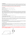
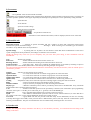
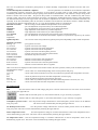
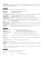
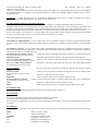
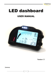
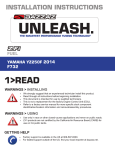
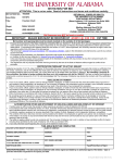
Main connector wiring (IGNIJET 2008 unit view):
The unit uses MULTILOCK connector with three sections of 20+16+12 pins, supplemented with a short bundle ended with
4pin connector. This bundle includes outputs for the stepper motor idle control. The main connector 20+16+12 pin has the
same arrangement of pins as Ignijet 2007. Cable reductions are made for individual motorbikes used between IGNIJET 2008
unit and motorbike cable bundle connector.
For some bikes the unit is made with a modified hardware (e.g. for Ducati the camshaft position sensor input is modified). For
specific applications please always contact the unit's manufacturer.
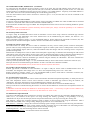
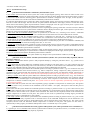
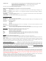
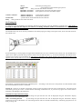
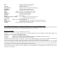
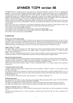
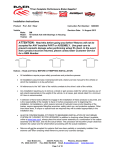
Some frequently used peripheries of the unit are brought out of the connecting bundle to 9-pin connector.
1
2
3
4
5
6
7
8
9
GEAR SHIFT LIGHT
N2O
START LIMITER
POT
+5V
CLUTCH MASTER
TACHO/LAMBDA
LAMBDA
SENSE GND
Description of pins:
1. Crankshaft position sensor CKPS.
An input is ready for standard inductive pickup sensors used on motorbikes as CKPS. One outlet of the CKPS will be
connected to connector (1) and the other outlet will be connected to SENSE GND (9). Polarity of the sensor is important for
proper function of the pickup system. Standard polarity is the one where the sensor produces in CKPS input positive voltage
when approaching the projection, and negative when moving away from it. Reverse polarity can be set using Ignijet 2008.exe
software on Synchro tab.
This input is made as standard for systems commonly used on motorcycles, always consult the possibility to use a different
pickup system with the manufacturer!!!
2. SPEED SENSOR
An input is ready for standard Hall speed sensors used on motorbikes. SPEED SENSOR is powered by reference voltage + 5 V
(10) and SENSE GND (9). Sensor outlet will be connected to connector (2). Configuration of speed measurement can be done
on "Gear" tab.
3. Air pressure sensor APS
An input is ready for standard types of atmospheric pressure sensors used on motorbikes. It is designed to bear voltage of 0 to
5 V. Correct sensor selection is based on motorbike type selection using the software, tab "Motorbike". The sensor
characteristics can be modified using the software, tab "Sensors".
APS is powered by reference voltage + 5 V (10) and SENSE GND (9). Sensor outlet will be connected to connector (3).
This input can also be switched off using the software. In such a case the AP correction is set as a default atmospheric pressure
of 100 kPa. Where APS is missing in the motorbike system (e.g. defect of sensor, pickup off), the function of atmospheric
pressure detection is taken over by the pressure sensor in IAPS (Intake Air Pressure Sensor measuring the pressure when the
engine is idle). In case there is neither APS nor IAPS, the unit will set the air pressure value to 100 kPa.
4. LAMBDA
An input is ready for standard lambda sensors (voltage for stoichiometric air–fuel mixture: 0.4 to 0.8 V), and for linear lambda
sensors with convertor (UEGO, Wideband). It is designed to bear voltage of 0 to 5 V. The voltage from the lambda sensor can
be used for the purpose of lambda-regulation of the mixture in the self-tuning mode, to display the lambda sensor voltage using
the software, or to display using the tachometer.
One LAMBDA sensor output is connected to connector (4) and the other output is connected to SENSE GND (9). The sensor
characteristics can be modified using the software, tab "Sensors".
5. Engine temperature sensor TWS
An input is ready for standard engine temperature sensors used on motorbikes. Correct sensor selection is based on motorbike
type selection using the software, tab "Motorbike". The sensor characteristics can be modified using the software, tab
"Sensors". Engine temperature value is used to configure the volume of fuel and advanced ignition.
With some motorbikes the unit also sends the data using K-line or CAN to the dashboard for display.
One outlet of TWS will be connected to connector (5) and the other outlet will be connected to SENSE GND (9).
This input can also be switched off using the software. In such a case the default temperature will be set to 80° C.
For the internal wiring of the input see the figure below:
6. Inhibit input BLOCK
One outlet of BLOCK signal (e.g. from stand switch and neutral switch) will be connected to connector (6) and the other will
be connected to SENSE GND (9) or GND (12, 13, 14). If BLOCK input is not grounded, the unit will be blocked. Grounding
on motorbikes is executed either by side stand switch (position "ride"), or by NEUTRAL switch connected via diode. The
blocking can be activated or deactivated on "Motorbike" tab.
7. START LIMITER input
One outlet of the Start limiter switch will be connected to connector (5) and the other outlet will be connected to SENSE GND
(9) or GND (12, 13, 14). Reverse polarity of the Start limiter switch can be configured using the software, tab "Motorbike".
If you activate the start limiter switch, the unit will either activate the "Start limiter" function, or "Pit speed control" function.
The setup of launch rev limiters is on the "Launch control" tab. When the start limiter switch is deactivated, the Post-start
limiters are activated ("Launch control" tab), or N2O injection delay (N2O tab).
8. DASHBOARD
Connection between the unit and the dashboard using K-line type serial communication. Some operational information is sent
to the dashboard using the serial communication (engine temperature - SUZUKI and YAMAHA bikes, speed - YAMAHA
bikes, gear engaged - Suzuki, Kawasaki bikes). The data are then displayed on the dashboard. Correct communication type
setup is based on motorbike type selection using the software, tab "Motorbike". Different communication type can be selected
using the "Motorbike" tab. DASHBOARD (pin 8) output should be connected following the chart.
To ensure proper display function the immobiliser reader must be disabled for Yamaha motorbikes!!!
9. SENSE GND
SENSE GROUND (9) is used for connection and supply of sensors.
10. Reference voltage + 5 V
Reference voltage +5V (pin 10) is used for the power supply of sensors.
11. Correction potentiometer POT
Voltage from the correction potentiometer can be used either to adjust the fuel or advance maps or to set the start limiter
value, or to adjust the acceleration limiter sensitivity (Launch control). The correction voltage can be between 0 and 5 V.
Linear potentiometer must be used with 1 - 10 kOhm values. Specific correction setup can be done using the software, tab
"Sensors". Voltage dependence of correction is linear with zero in the middle of the potentiometer scale (for 2.5 V voltage no
correction is set). POT is powered by reference voltage + 5 V (10) and SENSE GND (9). Potentiometer outlet will be
connected to connector (11).
12. 13. 14. ground (GND)
The power grounding (GND) will be connected to the outlets (12, 13, 14).
15. Revolution indicator output TACHO
The revolution indicator output is compatible with majority of dashboards used on motorbikes. Pulse number for one
revolution and possible corrections are set using the software, tab "Motorbike". TACHO output will be connected to connector
(15).
When AFR function is activated, the air-fuel ratio can be displayed on the tachometer, re-calculated from the lambda sensor
voltage. AFR display parameters on the tachometer are set on Motorbike tab. AFR function can be activated using SWITCH
multifunction input. SWITCH input has more functions defined on "Tuning" tab.
16. FUEL PUMP RELAY output
Fuel relay activates for about 4 s after the unit is switched on and remains active while the engine is running. One fuel pump
relay outlet will be connected to connector (16) and the other one will be connected to the switched + 12V. Connect the
switched fuel pump relay circuit following the diagram. Be careful about the fuel pump polarity!!!
17. N2O injection output
Maximum N2O injection valve output current can be 10 A (for a short period of about 30 sec). N 2O injection is conditioned
upon the power output 2 setup 2 (pin 17) as N2O ("Power out" tab), and N2O function must be activated (N2O tab), plus TPS
min and RPM min conditions must be met ("N2O" tab).
Setup of N2O launch, delay of N2O after ignition, advance retard and its delay settings after ignition are adjusted using the
software, N2O tab.
One N2O injection valve (relay) outlet will be connected to connector (pin 17) and the other one will be connected to the
switched + 12V.
WARNING!!! WHERE THE ELECTROMAGNETIC VALVE IS CONNECTED DIRECTLY TO THIS OUTPUT, IT
IS ALWAYS NECESSARY TO BRIDGE IT USING SO-CALLED ZERO DIODE WITH CURRENT VALUE OF AT
LEAST 5 A!!! SEE THE FIGURE BELOW:
18. GEAR SHIFT LIGHT, POWER OUT 1, 2 indicator
To control the gear shift indicator the power outputs 1 and 2 can be used. The gear shift indicator output can bear max. 5 A
current (bulb of up to 50 W) for a short period of time (tens of seconds). Permanent load is possible to max. 2 A. Gear shift
indicator function is conditioned upon the setup of power output 1 or 2 as Shift indicator. Frequency of the Shift indicator is
set on "Race" tab in two levels (the first blinking, the second shining permanently).
One Gear shift indicator outlet will be connected to connector (pin 17 or 18) and the other one will be connected to the
switched + 12V.
19. Camshaft position sensor CMPS
An input is ready for standard inductive pickup sensors used on motorbikes as CMPS. One outlet of CMPS will be connected
to connector (19) and the other outlet will be connected to SENSE GND (9).
Some motorbikes use Hall sensor type as CMPS. The unit adjustment for these sensors uses the connecting bundle for specific
motorbike.
This input is made as standard for systems commonly used on motorcycles, always consult the possibility to use a different
pickup system with the manufacturer!!!
20. Throttle position sensor TPS
An input is ready for standard TPS sensors used on motorbikes. Correct sensor setup is based on motorbike type selection
using the software, tab "Motorbike". The sensor characteristics can be modified using the software, tab "Sensors". It is
designed to bear voltage of 0 to 5 V.
TPS is powered by reference voltage + 5 V (10) and SENSE GND (9). Sensor outlet will be connected to connector (20). This
input can also be switched off using the software. In such a case IAPS sensor should be available.
21. Intake air pressure sensor IAPS
The IAPS sensors are usually the same as APS on motorbikes, but they read air intake pressure instead of atmospheric
pressure. There is always underpressure in the atmospheric engines' air intake system. There is underpressure in the air intake
system of turbocharged engines (idle run, small and medium load) that changes with the increasing load to overpressure
(medium and high load).
Measurement of underpressure in the air intake of the atmospheric engines helps to determine the fuel dosage for idle run and
small load or in the cases where TPS is missing in the system. In turbocharged engines it helps to determine the fuel dosage for
the entire engine load range. In case there is no IAPS in the system, the unit determines the dosage using TPS only.
Correct sensor selection is based on motorbike type selection using the software, tab "Motorbike". The sensor characteristics
can be modified using the software, tab "Sensors".
IAPS is powered by referential voltage + 5 V (10) and SENSE GND (9). Sensor outlet will be connected to connector (21).
This input can also be switched off using the software. In such a case TPS sensor should be available.
Where there are no TPS and IAP sensors, the unit will set the base injection time 2mS!!!
22. Secondary throttle position sensor STPS
Exhaust pipe throttle is installed in some motorbikes. An input is ready for sensors used in standard throttle servos on
motorbikes. It is designed to bear voltage of 0 to 5 V. Servo can be adjusted using "Servo" tab - "Servo EX".
STPS is powered by reference voltage + 5 V (10) and SENSE GND (9). Sensor outlet will be connected to connector (22).
Exhaust throttle engine conductors are led to 47 and 48 pins.
23. Air temperature sensor ATS
An input is ready for standard thermo sensors used on motorbikes. Resistance/temperature dependency is usually the same as
with water temperature sensors. Correct sensor selection is based on motorbike type selection using the software, tab
"Motorbike". The sensor characteristics can be modified using the software, tab "Sensors".
One outlet of ATS will be connected to connector (23) and the other outlet will be connected to SENSE GND (9).
This input can also be switched off using the software. In such a case the default AT correction for air temperature will be set
to 50° C.
WARNING!!! Kawasaki ZX12R uses different air intake temperature sensor - it is necessary to replace it with a different one
(from different type of motorbike), or not to use it (to disconnect it or switch it off).
24. Multifunction input SWITCH
One outlet of the SWITCH will be connected to connector (24) and the other outlet will be connected to SENSE GND (9) or
GND (12, 13, 14). Function of this input is set using "Tuning" tab. Polarity (grounding or de-grounding) is set sing
"Motorbike" tab. If you activate the input, the unit will perform the function you can pre-set using the "Tuning" tab.
AFR function - changes the revolution measuring signal to display of current air-fuel ratio using the tachometer. AFR is
determined from lambda sensor voltage reading. Display proportions are set on "Motorbike" tab.
AFR function + Autotuning - changes the revolution measuring signal to display of current air-fuel ratio using the tachometer.
AFR is determined from lambda sensor voltage reading. Display proportions are set on "Motorbike" tab. Autotuning function
will be activated simultaneously. Autotune proportions are set using "Tuning" tab.
Autotuning function - only the Autotuning function will be activated.
Block launch control function - will block the Launch control function.
25. CLUTCH MASTER input
One outlet of the CLUTCH MASTER will be connected to connector (25) and the other outlet will be connected to SENSE
GND (9) or GND (12, 13, 14). If you activate CLUTCH MASTER switch, the unit will reduce the engine power for certain
period of time to allow easier changing up. The power reduction is performed by switching off the ignition, or by lowering the
advance angle, or by switching off the injection. This process provides for higher gear shift without clutch and throttling down,
thus minimizing the time losses during gear shifting. The blocking time for individual gears can be set using the software,
"Race" tab. Reverse polarity of the CLUTCH MASTER switch can be configured using the software, "Motorbike" tab.
26. FALL SENSOR
One outlet of the Fall sensor will be connected to connector (26) and the other outlet will be connected to SENSE GND (9) or
GND (12, 13, 14). When the Fall sensor is activated, the unit will block the ignition with a 1.5 s pause. Reverse polarity of the
Fall sensor can be configured using the software, "Motorbike" tab. The Fall sensor can be activated or deactivated on
"Motorbike" tab.
Honda motorbikes do not have the Fall sensor included in the unit, but the sensor is controlled via power supply relay.
27. 28. 29. 30. Ignition coils IC1, IC2, IC3, IC4
Ignition coils' outputs are ready for standard types, designed for inductive ignition and used on injection-type motorbikes
(primary coil resistance approx. 1 to 2 Ohm).
One outlet of the ignition coil will be connected to key switched + 12 V, and the other one will be connected to the
corresponding connector pin - IC1 (28), IC2 (27), IC3 (29), IC4 (30).
In line engine configuration applies only to motors with cylinder order 4-3-1-2. For double cylinder motors IC 1 and IC 4
represent the front cylinder and IC 2 and IC 3 the rear cylinder.
31. COOL RELAY fan switch output
The fan switch output will be connected to the cooling relay following the wiring diagram. Relay inlet will be connected to
cooling output COOL RELAY using one outlet (31), and the other outlet will be connected to key switched + 12V. Connect
the switched relay circuit following the diagram. When the unit is switched on this output will switch on for about 1 s and
make the fan turn. This serves the purpose of fan function check. Reverse polarity of the fan switch can be configured using
the software, "Motorbike" tab.
32. Supply voltage +12 V
Nominal supply voltage is 14 V. It must be within 8 - 16 V range. In this range the unit is able to provide optimal control of all
the processes. Supply voltage is connected to outlet +12 V (32).
33. 34. 35. 36. Main injectors INJ1, INJ2, INJ3, INJ4
Injector outputs are ready for standard injector types used on motorbikes (coil resistance approx. 13 Ohm). One outlet of
injectors will be connected to key switched + 12 V, and the other one will be connected to the corresponding connector pin
INJ1 (35), INJ2 (36), INJ3 (34), INJ4 (33).
In line engine configuration applies only to motors with cylinder order 4-3-1-2. For double cylinder motors INJ 1 and INJ 4
represent the front cylinder and INJ 2 and INJ 3 the rear cylinder.
37. 38. 39. 40. Secondary injectors INJ1B, INJ2B, INJ3B, INJ4B
Injector outputs are ready for standard injector types used on motorbikes (coil resistance approx. 13 Ohm). One outlet of
injectors will be connected to key switched + 12 V, and the other one will be connected to the corresponding connector pin
INJ1B (40), INJ2B (39), INJ3B (38), INJ4 (37).
In line engine configuration applies only to motors with cylinder order 4-3-1-2. For double cylinder motors INJ1B and INJ4B
represent the front cylinder and INJ2B and INJ3B the rear cylinder.
41. Secondary throttle position sensor STPS2
This input is designed for voltage reading of the secondary throttle position. It is usually installed between the main throttle
and the suction branch, driven by either stepper or DC motor.
An input is ready for sensors used in standard servos on motorbikes. It is designed to bear voltage of 0 to 5 V. Suction servo
can be adjusted using "Servo" tab - "Servo IN".
STPS2 is powered by reference voltage + 5 V (10) and SENSE GND (9). Sensor outlet will be connected to connector (41).
Servo motor conductors are led to 43, 44, 45, and 46 pins.
42. GEAR POSITION SENSOR
Serves the purpose of identification of engaged gear (Suzuki, Kawasaki). An input is ready for standard sensors used on
motorbikes. Correct sensor selection is based on motorbike type selection using the software, tab "Motorbike". The sensor
characteristics can be modified using the software, tab "Gear".
One outlet of the GEAR POSITION SENSOR will be connected to connector (42) and the other outlet will be connected to
SENSE GND (9).
For the internal wiring of the input see the figure below:
43. 44. 45. 46. Air throttle servo outputs SM1A, SM1B, SM2A, SM2B
Outputs are ready for DC motor (43, 44) or stepper (one coil outputs 43, 44 and the other coil outputs 45, 46), or combination
of two DC motors (e.g. Yamaha R6 2008 - electromotor-controlled throttle + extended and reduced suction branches - intake
port).
47. 48. Outputs for exhaust throttle servo
The outputs are ready for DC motor.
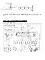
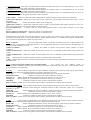
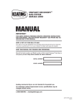
Standard wiring of injection system using IGNIJET 2008 unit:
2. IGNIJET 2008 Software
1) Pull down menus
File
New
- default settings (serial adjustment)
WARNING!!! Clicking New results in automatic default settings of all parameters (serial adjustment) for the motorbike. Even
though this default setup will adjust most parameters of the motorbike concerned correctly, but it does not guarantee optimum
operation of the engine. Especially the fuel maps will probably have to be optimized.
New for current tab
Open
Open from exe dir
software is located.
- default data settings (serial adjustment) only for the current tab.
- opens data file.
- opens the data file in the directory, where the running IGNIJET2008.EXE control
Open for current tab
Save
Save to exe dir
is located.
- opens data file for the current tab only.
- saves data file.
- saves the data file in the directory, where the running IGNIJET2008.EXE control software
Print
Exit
- prints the current settings.
- exits the program.
Port
Com disconnected
Com Auto
Com 1...
- disconnects the serial port concerned.
- automatically detects the relevant Com port, provided active unit is connected to it.
- manual setup of the communication port (only the ports existing in PC are displayed).
Ignition
Read
Verify
Program
Reset
- reads data from the unit.
- compares data in PC with data in the unit.
- sends data to the unit and performs verification.
- activation results in HW reset (restart of the unit).
Injection 1234
Separate
Locked
1=2=3=4
- includes options of TP maps control settings mode.
- separate map control for cylinders 1, 2, 3, 4.
- locked map control for all cylinders using Map 1.
- equality of the maps - Map 1 is used (all the maps are the same as Map 1).
Auxiliary
Minus
- minus one unit of the parameter.
Plus
- plus one unit of the parameter.
Back
- one step back.
Again
- one step forward.
On - off tuning - autotuning on / off.
Interpolation
- performs interpolation (linear arrangement) of the marked cells in the active map or curve.
External monitor
Display monitor
- displays the external monitor.
Upload monitor
- opens dialogue window to upload monitor from file.
Save monitor
- opens dialogue window to save monitor settings to file.
Set 1- 3
- activates monitoring set 1-3 (described in the External monitor manual).
Empty
- activates custom monitoring set (described in the External monitor manual).
The external monitor is described in a separate document: Ignijet_2008 – External monitor.
Language
English
German
Czech
Help
Help
- opens Installation guide from the internet (this file).
About the program
- data on the software (version, date).
2) Icon menu
- sets up default values for the selected motorbike.
WARNING!!! Even though this default setup will adjust most parameters of the motorbike concerned correctly, but it does not
guarantee optimum operation of the engine. Especially the fuel maps will probably have to be optimized by tuning the brake.
- opens data file.
- saves data file.
- prints the current settings.
- Back and Again commands.
- see pull down menu Device.
- information on the communication status, if this is displayed, the unit is not connected.
3) Motorbike tab
Motorbike selection
- - selection of specific motorbike that sets a number of values and connections between them
related to the specific motorbike settings.
Warning!!! When selecting new motorbike type the software
will offer to set up default values for all parameters.
Special settings
- by ticking this box "Synchro" tab will become visible that allows modifications of the sensor
system configuration and its parameters, and changes to induction coils' excitation.
Modify the settings only in the case you are completely sure you know what you're doing, or after consultation with the
manufacturer.
Note
- field for user remarks.
Fall sensor
- defines whether the fall sensor will be used or not.
Blocking allowed
- defines whether the blocking from side stand will be used or not.
Switch activation
- input logic setup. If the box is checked, the related function is activated by switching on input to
ground. If the box is not checked, the function is activated by switching off input from ground.
The above-mentioned information means that unchecked box automatically activates the function, until the related input is
connected to ground!!!
Limiters
- selection of value settings for rev limiters.
Ignition limiter
- rev value, above which the rev limiter using ignition cut will be activated.
Injection limiter
- rev value, above which the rev limiter using injection cut will be activated.
Ignition delay limiter
- rev value, above which the rev limiter using advance cut will be activated.
Ignition delay
- proportion of advance reduction above the value of rev limiter using advance cut.
Cooling
- temperature value, above which the output for switching engine cooling fans will be activated.
RPM
- selection of mode and setup of tachometer output correction.
Lambda on RPM
- setup of sensitivity of display for air-fuel ratio using the tachometer.
Display type
- definition what data protocol will be provided by K-line bus to the dashboard. Every motorbike
mentioned here has a specific K-line bus protocol.
CAN
- definition what data protocol will be provided by CAN bus (CAN connected to 9pin programming
connector canon (pin 8 - CAN HI, pin 6 CAN LOW, pin 5 - ground). CAN is HI SPEED type.
Display type
Every motorbike mentioned here has a specific CAN bus protocol.
Speed
- here different communication speed of CAN bus can be selected. However, be aware that this is
not possible in the event you use original dashboards, because they would not work.
No record
- Ignijet 2008 unit does not provide CAN data solely for the dashboards, but also for recording
(currently data loggers from AIM). These processes have a different data protocol, but they share the communication speed
with the given dashboard. This part of communication can be switched off by checking the box "No record".
4) Synchro tab
Synchro tab settings are always included in the delivery. If not absolutely necessary, we recommend not intervening in the
setting on this tab!!!
- The tab is divided in five parts.
Part 1 - Synchronization setup
1.
- pull down menu that defines crankshaft synchronization system.
a) min 2 lobes out means that the sensor system has n lobes of equal angular spacing, and at least two lobes are left out in
defined place. Every lobe has its initial and end edge. The unit searches for phase (distance between the same edges), which is
at least twice shorter than the following phase. Synchronization condition is displayed in the far right, section Synchro 1
special. Lobe number one is the first lobe after the identified synchronization condition.
b) 1 lobe out means that the sensor system has n lobes of equal angular spacing, and one lobe is left out in defined place. Every
lobe has its initial and end edge. The unit searches for phase (distance between the same edges), which is at least three times
shorter than 2x the following phase. Synchronization condition is displayed in the far right, section Synchro 1 special. Lobe
number one is the first lobe after the identified synchronization condition.
c) 1 lobe out ver 2 means that the sensor system has n lobes of equal angular spacing, and at least one lobe is left out in defined
place. The unit searches for more synchronization conditions that are displayed in the far right, section Synchro 1 special. Lobe
number one is the first lobe after the identified synchronization conditions.
d) Cam means that the crankshaft reading system is symmetrical (no lobe left out) , consisting of two sensors - crankshaft
(CKPS) and camshaft (CMPS). Lobe number one is marked the one that follows the first after CMPS lobe in real time.
e) Cam Honda means that the crankshaft reading system is symmetrical (no lobe left out) , consisting of two sensors crankshaft (CKPS) and camshaft (CMPS). Lobe number one is marked the one that follows the first after two CKPS lobes
inserted between two adjacent CMPS lobes in real time. This system is used only by Honda (and not always).
f) 1 inch means that the synchronization for ignition and injection is executed only by one lobe on crankshaft or camshaft, and
the unit is just searching for initial and end edge of the lobe, or vice versa.
g) shifted inch means that the sensor system has n lobes of equal angular spacing, and one of the lobes is angle-shifted against
the other lobes. Synchronization conditions are displayed in the far right, section Synchro 1 special. Lobe number one is the
first lobe after the identified synchronization conditions.
h) inserted lobe means that the sensor system has n lobes of equal angular spacing, and one synchronization lobe is inserted
between the lobes in defined place. Synchronization conditions are displayed in the far right, section Synchro 1 special. Lobe
number one is the first lobe after the identified synchronization conditions.
i) special synchronization settings - this option enables any changes to the synchronization conditions (see Part 5).
2.
- pull down menu that defines camshaft synchronization (whether the system will be fully sequential, and how
this will be achieved.
a) Synchro 1 solved means that the system is fully sequential already by setting the pull down menu 1. (e.g. system Cam or
Cam Honda).
b) Cam means that the system defines the crankshaft position according to pull down menu 1 (e.g. min 2 lobes left out), and
becomes fully sequential by detecting lobe on the cam with every second rev. Lobe number one is marked the first tooth after
the gap on the crankshaft, whereas in the same (or previous) revolution CMPS signal was detected.
c) Swing means that the system defines the crankshaft position according to pull down menu 1 (e.g. min 2 lobes left out), and
becomes fully sequential when selected sections (e.g. before compression, during compression, during expansion) on the
crankshaft will be time-measured and compared. The mutual length of the sections will determine whether compression or
exhaust rev took place. This system cannot be used for sequentially symmetrically working engines (e.g. inline four-cylinder).
c) Swing 1 cylinder means that the system defines the crankshaft position according to pull down menu 1 (e.g. min 2 lobes left
out), and becomes fully sequential when selected section on the crankshaft will be time-measured in one revolution, and the
same section will be measured again in the following revolution. Time comparison of the sections will determine whether
compression or exhaust revolution took place. This system cannot be used for sequentially symmetrically working engines
(e.g. inline four-cylinder).
e) None means that the system will work semi-sequentially (group), regardless of compression or exhaust cycle. The ignition
system will work at every revolution of the crankshaft (even into exhaust - lost spark). The injection will also take place at
every revolution.
f) IAP means that the system defines the crankshaft position according to pull down menu 1 (e.g. min 2 lobes left out), and
becomes fully sequential when in selected sections of the crankshaft (e.g. section before suction, during suction, after suction)
underpressure in the air intake of one cylinder will be measured. The values will be compared, and the result will determine
whether compression or exhaust rev took place. The system can also work on symmetrically working engine, provided the
underpressure sensor is connected only to one cylinder.
g) IAP single cylinder means that the system defines the crankshaft position according to pull down menu 1 (e.g. min 2 lobes
left out), and becomes fully sequential when in selected section on the crankshaft underpressure will be measured in one
revolution, and in the same section air intake underpressure will be measured again in the following rev. The values will be
compared, and the result will determine whether compression or exhaust rev took place. The system can also work on
symmetrically working engine, provided the underpressure sensor is connected only to one cylinder.
3.
- pull down menu that defines how many ignition and injection cycles will be performed in one crankshaft rev.
a) 1 ignition per 2 revs (camshaft) means that the synchronization condition (see pull down menu 1) is recorded once per two
revs of the crankshaft, the system being implicitly sequential.
b) 1 ignition per 1 rev means that the synchronization condition (see pull down menu 1) is recorded once per one rev of the
crankshaft, the system being either sequential or semi-sequential.
b) 2 ignitions per 1 rev means that the synchronization condition (see pull down menu 1) is recorded twice per one rev of the
crankshaft, the system being either sequential or semi-sequential.
d) 3 ignitions per 1 rev means that the synchronization condition (see pull down menu 1) is recorded three times per one rev of
the crankshaft, the system being either sequential or semi-sequential.
Value transfer - defines on which lobe of the reading disk the measured values will be transferred for calculation.
Synchro max rpm [rpm] - defines up to how many revs per minute the synchronization from pull down menu 1 will be
performed.
Number of lobes
- defines the number of lobes on the reading disk.
Ignition after synchro 1 - enables fully sequential system to work in semi-sequential mode (ignite and inject at every rev).
This option mostly makes easier the start of fully sequential system.
Every 2nd injection out - in specific cases (e.g. when semi-sequential system is used) allows omission of every other
injection.
Reverse polarity of crank sensor - defines the polarity of crankshaft sensor.
Reverse polarity of cam sensor - defines the polarity of camshaft sensor.
Standard polarity means that when lobe approaches the sensor the latter will produce positive voltage to the unit, and when
moving away from the sensor it will produce negative voltage (CKPS input pin 1), or CMPS (pin19) against SENSE GND
(pin 9). With reverse polarity the voltages are also reversed.
Part 2 - Channels
- this section defines the number of cylinders, the number of left out, or shifted lobes on the
distributor disk, an assignation of individual channels 1 - 4 to the distributor disk lobes, and their location at the beginning or at
the end of a lobe. Parameters to be set:
Number of cylinders
- defines the number of ignition and injection outputs (number of engine
cylinders).
Number of lobes left out - defines the number of lobes left out in the case of crankshaft synchronization using left out lobe
system.
Number of shifted lobes - defines the number of lobes shifted in the case of crankshaft synchronization using shifted lobe
system.
Lobe - defines the lobe, on which the ignition advance of related cylinder will be made.
2. Edge - defines edge of the lobe, on which the ignition advance of related cylinder will be made. Checking means use of end
edge of the lobe.
Part 3 - Swing, Swing single cylinder, IAP, IAP single cylinder
- this section has four different modes of
synchronization of camshaft, according to the selected synchronization in pull down menu 2 in Part 1 - Synchronization setup.
Every mode has its own parameters.
a) Swing
- allows finding synchronization of the camshaft by analysing uneven operation of the engine. Times of three
selected sections during the crankshaft rotation are compared. Parameters to be set:
Midsection
- defines whether the midsection will be the longest or the shortest of all three.
Monitored sections
- defines the sections to be monitored (numbers of lobes).
Previous rev
- defines whether the monitored section was in the previous or in the current rev.
Meeting rev
- defines whether the synchronization condition is met by even or odd rev.
Min RPM
- minimum revolution to search for the synchronization condition.
Min rev number- number of revs from ignition, after which the synchronization condition will be searched.
b) Swing single cylinder - allows finding synchronization of the camshaft by analysing uneven operation of the engine.
Time of selected section during the crankshaft rotation in three consecutive engine revs is compared.
Parameters to be set:
Midsection
- defines whether the section in middle rev will be the longest or the shortest of all three compared.
Monitored section
- defines the section to be monitored (numbers of lobes).
Meeting rev
- defines whether the synchronization condition is met by even or odd rev.
Min RPM
- minimum revolution to search for the synchronization condition.
Min rev number- number of revs from ignition, after which the synchronization condition will be searched.
c) IAP
- allows finding synchronization of the camshaft by analysing pressure changes in the air intake. Pressure in
three selected sections during the crankshaft rotation are compared. Parameters to be set:
Mean value
- defines whether the midsection pressure will be the highest or the lowest of all three compared.
Monitored sections
- defines the sections to be monitored (numbers of lobes).
Previous rev
- defines whether the monitored section was in the previous or in the current rev.
Meeting rev
- defines whether the synchronization condition is met by even or odd rev.
Min RPM
- minimum revolution to search for the synchronization condition.
Min rev number- number of revs from ignition, after which the synchronization condition will be searched.
b) IAP single cylinder
- allows finding synchronization of the camshaft by analysing pressure changes in the air intake.
Pressure in selected section during the crankshaft rotation is compared in three consecutive engine
revs. Parameters to be set:
Midsection
- defines whether the section in middle rev will be the longest or the shortest of all three compared.
Monitored section
- defines the section to be monitored (numbers of lobes).
Meeting rev
- defines whether the synchronization condition is met by even or odd rev.
Source
- defines the sources of underpressure measurement after the synchronization. Whether the source
will be intake air underpressure reading input (IAP - pin 21), or atmospheric pressure reading input (AP - pin 3). In the case of
AP the atmospheric pressure will be measured, as well as when AP sensor is missing - by IAP reading when the engine is off.
Min RPM
- minimum revolution to search for the synchronization condition.
Min rev number- number of revs from ignition, after which the synchronization condition will be searched.
Part 4 - Excitation
In this part the ignition coil excitation parameters are set. For the ignition coils with lower
resistance 1-2 ohm the excitation time is usually set to 1500 - 2000 µs, for the ignition coils with resistance 2-4 ohm it is
usually 2500 - 4000 microseconds.
Dynamic excitation component %
- equals per cent angle increment (how many angle per cent from one rev) to the
base excitation time.
Max rpm for thumb excitation - defines the number up to which the excitation will it be calculated, but derived
physically from the reading system lobes.
It is always necessary to follow the ignition coil manufacturer's instructions. Failure to observe the prescribed time may result
in destruction of the control unit or ignition coil.
Part 5 - Synchro 1 special
- In this part it is possible to freely adjust synchronization conditions for the crankshaft in
Special synchro setup mode, pull down menu 1 - Synchronization setup.
Evaluation edge - defines the edge where the synchronization condition is evaluated. 1. means initial edge and 2 means the
end edge of a lobe.
Number of monitored edges
- defines whether only one edge, or both edges of a lobe will be used to define the sections
for the purpose of evaluation of synchronization condition.
5) General instructions regarding the setup maps
The maps are controlled very similarly to spreadsheets (MS Excel, Open Office Calc). Standard marking, copying and
inserting individual cells and entire map sections are available. Highlighted cells can also be inserted in other parts of the map,
or into a spreadsheet using CTRL+C and CTRL+V commands.
Corners of highlighted cells include green triangles that serve the cursor-activated interpolation function (linear fit) between
the left, or the upper left cell, and the right, or lower right cell; the action has to be confirmed by clicking into the triangle, or
using CTRL+I command.
Move the cursor to the lower right edge - cross will appear. After activation by left-click the selected cell(s) can be copied into
the neighbouring space to any direction. Individual cells or selected fields can be upsized or downsized using the scroll wheel,
by arrows near the cursor, by double-arrow over the map or F4 (less), or F5 (more) keys.
One step on the advance map equals 1° of the advance, for fuel maps it is always one per cent from the currently displayed
value. Where the display is switched to curves, it is possible to change the shape of the curve using cursor directly. When the
engine is running and PC connected with the unit, active segment in the fuel map is highlighted. When the engine is running
the active segment can be upsized or downsized using F4 and F5 keys. If the goal is to program the values into the unit with
every parameter change, Programming after change box should be checked.
6) Advance tab
Map includes 15 adjustable revolution options x 10 options for throttle position.
Base advance
-defines mechanically established basic (minimum, ignition) advance.
Correction for cylinder 1,2,3,4 - serves to adjust the advance of individual cylinders.
Pick-up correction
- serves to phase-frequency adjustment of the pickup system. Reading input of the crankshaft
depends on the frequency. If the input is not correctly configured, it displays deviation depending on the revs for the set and
actual advance value. Frequency dependence for pickup system with a small number of lobes is different from pickup system
with a high number of lobes.
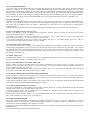
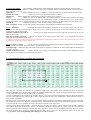
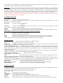
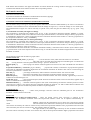
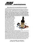
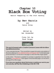
7) Tabs Injection 1, Injection 2, Injection 3, Injection 4
TP map serves the purpose of setting the fuel supply in medium and high load range (area C on the figure below). IAP map
serves the purpose of setting the fuel supply in medium and high load range (area A). Transition area B is defined by four
values (TPS min, TPS max, RPM min and RPM max). In the transition area both the maps with weighted average are used to
set the fuel supply.
RPM [1/min]
0
1000
2000
3000
4000
5000
6000
7000
8000
9000
10000
0
1
2
TPS [%]
3
4
5
6
7
8
9
10
IAP map provides for fuel dosage supply in the whole range ÷ 100 % TPS in case the IAPS is not connected. Setting the fuel
supply in this area using TP map displays more stable parameters than setting by IAP map.
TP map includes 15 adjustable revolution options x 10 options for throttle position.
8) Tab Injection B
Map B provides for the setup of fuel supply ratio using the main and the secondary injector. Value 0 to 100 [%] in the
individual cells defines what portion of the entire fuel dose will be realized by the secondary injector.
9) Tab Injection IAP
IAP map serves the purpose of setting the fuel supply in low load range and idle run. Low load area is defined on Injection 1
tab. IAP map provides for fuel supply settings in the entire working range in case the TPS is not connected. Idle run setting by
IAP map usually displays more stable parameters than setting by TP map.
10) Position tab
Here the injection position is defined. The curve includes 15 adjustable position points related to the revs. The position is
defined by the angle before TDC compression stroke. The position of beginning, middle or end of injection can be selected.
The position can be defined separately for both the injector groups.
To set the curves the same options apply as for the advance or fuel maps.
11) Corrections tab
Corrections after ignition
- post-ignition enrichment at "cold" start can be defined. Both the time and enrichment
value curves can be modified. The post-ignition enrichment values are set for water temperature -10 °C. For higher
temperatures the post-ignition enrichment values are linear-decreased, and for water temperature higher than 80 °C they equal
100% (no enrichment).
Acceleration plus-injection
- when the throttle is opened too fast, the pressure in the air intake increases dramatically.
Fuel supplied by synchronous injections is deposited on the suction pipe surfaces more intensively due to the higher pressure.
The result is poorer quality of the supplied mixture. Therefore at the moment of acceleration (when the throttle is opening fast)
asynchronous additional injections are performed into all cylinders.
Acc. threshold [%/s]
- minimum throttle movement speed needed to activate the acceleration plus-injection. It is
defined by the curve related to the throttle position.
Size
[ms]
- the map of size (time) of acceleration plus-injections repeated with 10 ms periodicity. These plusinjections are performed for the time of movement of the throttle, until the throttle movement speed is higher than Acc.
threshold value. The map is defined by revs versus throttle position.
The size of asynchronous acceleration plus-injections is further thermally compensated on thermal correction tabs (Acc.
injection).
Acceleration injection enrichment / depletion
- here the parameters are defined for the acceleration adjustment
of synchronous injections (sensitivity and response) at swift change of engine load (at swift throttle movement), and
immediately afterwards. The situation at abrupt opening of the throttle is described above. The situation at abrupt closing of the
throttle is similar with reverse effect - the pressure drop results in enriched mixture. The new conditions may take several
seconds to settle. The purpose of the acceleration corrections is to adjust these undesirable dynamic changes. These phenomena
are demonstrated mainly in lower engine loads. The acceleration adjustments are made at the time of throttle movement, but
especially at the time immediately after the movement is finished. The acceleration enrichment volume is further thermally
compensated on thermal compensation tab Acc. cor. (only the enrichment values are compensated).
Thermal corrections
- tabs for settings of individual thermal adjustments for air and coolant.
Injection
- per cent adjustment of injection time by the coolant temperature.
Injection/V.
- per cent adjustment of injection time by the air intake temperature.
Advance
- angle adjustment of the advance by coolant temperature.
Advance/V.
- angle adjustment of the advance by air intake temperature.
Acc. injection
- per cent adjustment of asynchronous plus-injection by the coolant temperature.
Acc. cor.
- per cent adjustment of acceleration enrichment / depletion of synchronous injection by the coolant
temperature.
Ignition injection
- curve of time values of asynchronous ignition plus-injection depending on the coolant temperature.
Injection corrections:
Starting corr.
U correction
TW correction
AT correction
AP correction
POT correction
ACC correction
Advance corrections:
TW correction
AT correction
POT correction
IDLE correction
- post-ignition correction.
- injection correction from voltage.
- injection correction from water temperature.
- injection correction from air temperature.
- injection correction from atmospheric pressure.
- injection correction from correction potentiometer.
- acceleration injection correction.
- advance correction from water temperature.
- advance correction from air temperature.
- injection correction from correction potentiometer.
- advance correction from the idle rev regulator.
Other corrections are displayed on the tab that can be used to monitor the unit's operation, namely in the acceleration processes
and temperature changes.
Threshold
- current value Acc. threshold depending on the current position TPS [%/s].
ACC corr
- current value of the acceleration correction of synchronous injections after temperature correction
[%].
Size
- current asynchronous injection value after temperature correction [ms].
Start inj.
- current asynchronous ignition plus-injection value [ms].
ACC TW corr
- current value of synchronous injection enrichment after temperature correction (Acc. cor.).
ACC Inj. corr
- current correction after start after temperature correction [%].
12) Sensors tab
TPS
- here the extreme values of TPS voltage [mV] for 0 % and for 100% can be set. The sensor can be switched
off by checking the upper left box.
- measures and sets 0% TPS (power on, unit connected with PC, no gas, necessary to program)
- measures and sets 100% TPS (power on, unit connected with PC, no gas, necessary to program)
Atmospheric pressure sensor - here the pressure-voltage characteristics of the atmospheric pressure sensor can be defined
using two points.
The sensor can be switched off by checking the upper left box.
Air intake pressure sensor
- here the pressure-voltage characteristics of the air intake pressure sensor can be defined
using two points. The sensor can be switched off by checking the upper left box.
Water temperature sensor
- here the temperature-voltage or resistance characteristics of the water temperature sensor
can be defined using 9-point curve. The sensor can be switched off by checking the upper left box.
Air temperature sensor - here the temperature-voltage or resistance characteristics of the air temperature sensor can be
defined using 9-point curve. The sensor can be switched off by checking the upper left box.
Lambda sensor
- here the characteristics of the lambda sensor can be defined using 6-point curve (AFR voltage).
- Default UEGO (linear wideband lambda sensor – Ignitech WB1 and Bosch LSU4.9).
- Default Standard (standard lambda sensor)
- Default CAN ID 802, AFR value is read from CAN bus in ID 802 process.
The sensor can be switched off by checking the upper box.
POT - selection of the mode and size of maximum correction from the potentiometer
Unused
- no correction.
Injection
- injection correction. Voltage 0 to 5 V corresponds to the fuel correction within -Range to +Range [%]. For
2.5 V the correction is zero.
Advance
- advance correction. Voltage 0 to 5 V corresponds to the advance correction within -Range to +Range [°].
For 2.5 V the correction is zero.
Start limiter
- Start limiter correction. Voltage 0 to 5V V corresponds to the Start limiter correction within -Range to
+Range [RPM], for 2.5 V the correction is zero.
Launch control - for Launch control correction see the Launch control tab.
12) Suction servo tab
Servo allowed - software activation of servo controller.
Per cent
- here you can select whether the servo will follow the required voltage or per cent opening. For per cent
mode the servo stops have to be defined.
Map mode
- map mode selection.
- revs and TPS.
- revs only.
- TPS only.
Hysteresis
- here you can select the accuracy of servo run. !!!Warning!!! - In case you set too low value there is a risk of
servo oscillation (under 200 not recommended).
Stepper
- here you can select whether the intake servo uses stepper or DC motor.
Period
- selection of stepper speed (higher number means lower speed), displayed only when the stepper is selected.
PID regulator - PID parameters are displayed only when the stepper is not selected.
1/P
- proportional contribution of PID regulator - reverse value.
I
- integration contribution of PID regulator.
D
- derivation contribution of PID regulator.
I Off
- millivolt value of approach to the set value, under which the I component will be switched off.
D Off
- millivolt value of approach to the set value, under which the D component will be switched off.
O
- per cent power shift for one direction of DC motor.
Polarity this option enables servo direction setup.
Plus drive moves in one direction regardless of whether the feedback increments have equal direction.
Minus - the drive moves in reverse direction compared to plus option, regardless of whether the feedback increments have
equal direction.
Auto - the drive goes in one direction looking for maximum, then in the other direction looking for minimum; where the
direction and increments are opposed, the output polarity is automatically switched so that the feedback direction and
increments are equal. The polarity is saved in the data memory of the control unit for the next start.
"Drive by wire" function
- intake servo is in specific cases used to control the main throttle. This can be
achieved by selecting specific machine on "Motorbike" tab. These are the motorbikes with original system (YZF-R1 from
2007 and YZF-R6R from 2006). This motorbike has no mechanical connection between the gas handle and the throttle. The
throttle movement is realized by servo, following the request from the gas handle potentiometer, according to the voltage
request map on Servo IN tab, or from Idle run tab. The higher value of the two will be realized. The above-mentioned means
that the requested angle of flaps is not necessarily equal to the gas handle angle.
Setup example:
1) Voltage extremes are set on "Sensors" tab from the potentiometer for zero angle of gas handle, and for fully open gas
handle.
2) Map or curve of voltage requests is set on Servo IN tab that corresponds to the user's requirements. This can be for example
smaller opening of flaps at lower revs (softer power launch), or opening flaps when decelerating (engine-braking at
deceleration can be modified) etc. Further it is necessary to check whether the highest requested voltage in the ma corresponds
to fully open flaps. If the request is smaller, the flaps will not fully open, if bigger than the maximum the flaps will hit the
stops, and the unit will be current-overloaded!!!
Further it is necessary to remember that the voltage request at zero load on Servo IN tab should have lower value than the
requirement on "Idle run" tab, because of those two requests the higher value is always realized.
PID regulator constants must be set so that the drive has the fastest possible overrun without overshooting.
3) Voltage requirements of the main throttle for idle run for various temperatures are set on "Idle run" tab.
The voltage of servo potentiometer is displayed at TPS position on the online values monitor. Separate bar chart and scale are
made for the system to display the status of the setup potentiometer.
Intake port - expansion or reduction of suction branches is a device defined for some motorbikes, e.g. YZF-R6R 08. It
enables changes to the length of suction branches when the engine is running. This happens by moving the branches towards
the flaps (extended branches), or away from the flaps (short branches). The suction branches are pushed against the flaps by
short servo run after the start. They remain there until the "Suction branch" rev value is reached on "Motorbike" tab.
Afterwards they are moved away by short servo run, and remain there until the revs fall under the above-mentioned value.
During the installation always check if the branches are resting on the flaps after the unit is switched on. If not, the servo
polarity in the cable bundle has to be changed!!!
13) Exhaust servo tab
Servo allowed - software activation of servo controller.
Per cent
- here you can select whether the servo will follow the required voltage or per cent opening. For per cent
mode the servo stops have to be defined.
Map mode
- map mode selection - revs and TPS.
- revs only.
- TPS only.
Hysteresis
- here you can select the accuracy of servo run. Warning!!! - In case you set too low value there is a risk of
servo oscillation (under 200 not recommended).
Stepper
- here you can select whether the intake servo uses stepper or DC motor.
Period
- selection of stepper speed (higher number means lower speed), displayed only when the stepper is selected.
PID regulator - PID parameters are displayed only when the stepper is not selected.
1/P
- proportional contribution of PID regulator - reverse value.
I
- integration contribution of PID regulator.
D
- derivation contribution of PID regulator.
I Off
- millivolt value of approach to the set value, under which the I component will be switched off.
D Off
- millivolt value of approach to the set value, under which the D component will be switched off.
PID constants must be set so that the drive has the fastest possible run without overshooting.
14) Idle run tab
Idle run regulation
- here you can select the idle run rev regulation method.
None
- no regulation of idle run air circulation takes place.
Intake servo
- regulation is performed using the servo of secondary air flaps. In this mode the requirements of the
secondary flaps for individual coolant temperatures must be defined.
Stepper without potentiometer - the stepper regulates the volume of circulating air using choke valve so that the engine
runs in the requested revs. Target revs are set according to the coolant temperature. For this mode conditions must be defined
under which the idle run regulation is not performed (from certain TPS and rev value). The regulation takes place only when
the motorbike speed is zero.
Stepper sets TPS min
- in this mode the stepper either moves the choke throttle stops, or choke valve of the circulating air.
Number of steps of the servo for individual temperatures must be defined here.
Inverse operation of the motor
- changes the rotation direction of the stepper.
Stepper period - stepper speed setup.
Start
- time, during which the stepper is running after switching on the unit (slightly more air at
the start). Functional in the stepper without potentiometer mode only.
Idle run regulation by advance - here you can regulate the idle run by changing the advanced ignition. Target revs are set
according to the coolant temperature. For this mode conditions must be defined under which the idle run regulation is not
performed (from certain TPS and rev value). The regulation takes place only when the motorbike's speed is zero.
Range [rpm]
- rev value up to which the idle run regulation takes place.
Regul range TPS x10 [%]
- rev value in tenths of % TPS up to which the idle run regulation takes place.
Hysteresis [rpm]
- defines the range of insensitivity to the regulation deviation.
15) Power out tab
Power output 1
- Multifunction output (type open collector) that can be set using the software to perform one of the pre-defined functions. One
terminal of the appliance will be connected to outlet 18 and the other to +12V.
Power output 1 is pre-defined as gear shift indicator switch by default.
Power output modes:
Off
- power output will not be activated.
Lambda heat - power output will heat the lambda sensor.
Pilot light
- power output will be active if revs are higher than the set value.
Special
- power output will be active according to the truth table, two TPS levels, three rev levels.
Hysteresis
- range of insensitivity to rev change that has to be overcome for the output to return to the previous status.
Power output 2
- Multifunction output completely equal to output 1, but with additional function for N2O control. One terminal of the
appliance will be connected to outlet 17 and the other to +12V. WARNING!!! When used for N 2O je the output must be
protected - see the section Hardware - pin 17.
16) Race tab
Clutch mode
- defines clutch master mode (skipped ignition or lower advance).
Min clutch RPM
Clutch inj.
Clutch advance
- minimum rev above which clutch master is activated.
- per cent fuel during clutch master.
- advance during clutch master.
Setup according to the gear engaged
- here you can set the values of several parameters depending on the gear engaged.
Gear shift indicator
- two-level gear shift light (blinks with the first revs, and shines with the second).
Clutch master
- clutch master time setting.
Clutch master pause
- the time after activation, during which the clutch master cannot be activated again.
Motorbike display - for the elected types (where K-line is used to communicate with the dashboard) it is possible to display
temperature instead of speed.
Pit speed control
- here you can set the speed regulator by reducing the advance when passing through the pit.
This function is activated by Start limiter input (functional only when the value "Maximum speed for launch
control", set on "Launch control" tab, is exceeded).
Speed
- maximum speed required.
Advance reduction P
- Proportional regulator gain (by how many steps per 1km/h of exceeding the required
speed the advance should be reduced).
Advance reduction I
- Integration regulator gain (by how many steps per second the advance should be reduced when
exceeding the required speed).
Min advance
- Minimum allowed advance when Pit speed control function is active ( -20° means 20° for TDC).
Min RPM
- Minimum revs, under which Pit speed control function will not be active.
17) Gear tab
Gear shift determination
Voltage
RPM/speed ratio
Automatic RPM/speed ratio
- defines the method of engaged gear determination.
- determination by sensor (GPS - gear position sensor).
- determination by calculation of RPM/speed ration with manual entry.
- determination by calculation of RPM/speed ration with automatic search.
Number of gears
- here it is necessary to enter the number of gears on the motorbike (except neutral).
GPS voltage
voltage values.
- GPS voltage entries for individual gears, setup fields on the right are for manual reading of the
RPM/speed ratio
ratio values.
- RPM/speed ratio entries for individual gears, setup fields on the right are for manual reading of the
Automatic RPM/speed ratio
- parameters for automatic RPM/speed ratio lookup.
Speedometer
- speed sensor settings.
Number of pulses
- number of pulses per 1s for 100 km/h (suitable for higher number of pulses - e.g. sensors in the
transmission).
Distance
- distance between the individual pulses in mm (suitable for lower number of pulses - e.g. one per wheel
rotation).
Corrections
- depending on the gear engaged it is possible to adjust the advance and injection, and acceleration threshold
for the acceleration limiter (Launch control tab).
18) N2O tab
This tab is visible only if N2O function is activated on Power out tab, pin 17.
N2O allowed
N2O
- software activation of N2O dosage controller.
N2O 1
- initial N2O percentage flow.
N2O 2
- final N2O percentage flow.
Launch time
- period between initial and final gas injection.
Delay
- delay period for start limiter activation.
Injection 1 correction - initial injection correction from N2O request.
Injection 2 correction - final injection correction from N2O request.
Advance reduction
Advance reduction 1
- initial advance reduction.
Advance reduction 2
- final advance reduction.
Launch time
- period between initial and final advance reduction.
Delay - delay period for start limiter activation.
19) Tuning tab
It is designed to set the parameters for automatic adjustment of fuel maps using the feedback to lambda sensor. This mode is
used only to adjust the fuel maps on test bench or on running motorbike. Under no circumstances it is recommended
for permanent motorbike operation!!!
The lambda sensor has to be correctly installed in the exhaust piping according to the figure below, about 300-700 mm from
the exhaust valve.
For the autotuning to work properly the signal from lambda sensor has to be connected to the control unit. The lambda sensor
signal can be further processed using connector between the unit and the sensor, e.g. for UEGO wideband). The lambda sensor
type has to be correctly set on the Sensor tab. The values in "Standard" and "UEGO" defaults must be adjusted according to the
specific sensor used to make sure V and AFR values are true. Where AFR signal is supplied by CAN bus ID 802, there are no
conversion issues, because the data are already in AFR format.
"Requested AFR" map is located on the right side of the tab.
Interpolation is performed between the individual points. According to the current revs and position of choke throttle (TPS)
the current demand for air/fuel is calculated.
Tuning on - if this box is checked, "autotuning" function will be activated in the unit when connected to PC. The same will be
achieved by pressing F6 on PC. T deactivate the autotuning uncheck the box, or press F6 key again. The current status is
marked by red highlight of the field name.
Multifunction input SWITCH settings
AFR function
- by activating the input the fuel ratio will be displayed using the tachometer. Display
proportions are set on "Motorbike" tab.
AFR + Autotuning function
- by activating the input the fuel ratio will be displayed using the tachometer. Display
proportions are set on "Motorbike" tab. Autotuning function will be activated simultaneously. Autotuning proportions are set
using "Tuning" tab.
Autotuning function
- by activating the input only the autotuning function will be engaged. Autotuning proportions are
set using "Tuning" tab.
Launch control blocking function
- by activating the input all the launch control functions will be deactivated
(Launch control tab).
Tuning method In points
In this mode the tuning deals only with one point in the active fuel map, provided none of
the conditions is met (see below).
Everywhere
- In this mode the tuning deals with four adjacent points in the active fuel map,
with the proportion corresponding to the point approaching actual value, and provided none of the conditions is met (see
below). "RPM tolerance" and "TPS, IAP tolerance" conditions are not used in this mode (invisible).
Limiting conditions
- The autotuning can be limited by several conditions:
.
RPM tolerance - where the engine revs are distant from the active rev column by more than the value (in our case 200 RPM),
the autotuning will not be performed. This limitation applies only for the "In points" tuning method.
TPS, IAP tolerance
- if TPS, or IAP pressure (absolute pressure in the intake) is distant by more than the value (in our
case 2%, or 2 kPa), the autotuning will not be performed. This limitation applies only for the "In points" tuning method.
AFR tolerance - value of deviation of the current AFR from the requested AFR (tenths of AFR), where the tuning is
already off (hysteresis).
Acc cor . max - where the acceleration correction value (see "Correction" tab) is higher than the value set (in our case 10%),
the autotuning will not be performed.
AFR min
- if the current AFR value is lower than (in our case 10 AFR), the autotuning will not be performed.
AFR max
- if the current AFR value is higher than (in our case 20 AFR), the autotuning will not be performed.
TPS min
- if the current TPS value is lower than (in our case 0%), the autotuning will not be performed.
RPM min
- if the current engine revs are lower than (in our case 800 RPM), the autotuning will not be performed.
Temperature min
- if the current engine temp value is lower than (in our case 40°C), the autotuning will not
be performed. Temperature max - if the current engine temp value is higher than (in our case 105°C), the autotuning will not
be performed.
Regulation proportions
Revs per step - this value says after how many engine revs the regulation interventions in fuel maps will be made. In our
case the regulation will be made always after 20 revs. From practical viewpoint the rule of thumb applies that step of 10-30
revs can be used where the lambda sensor is located in the exhaust collector. Where the lambda sensor is plugged using intake
tube in the exhaust end piece, the operation delay of the measured gas should be considered, and the value set within 40-100
revs. The end piece measuring tube arrangement is not exactly suitable, because it prolongs the time necessary to set the fuel
maps, and represents risk of undesirable influence over AFR reading from the environment, especially for the single and
double cylinder engines of large volume in low revs. Further you should remember that too small a number of revs per step
will result in "oscillation" of the tuning process, and too high a number of revs per step will result in a lengthy tuning process.
Step [%/AFR] - this value says by how many per cent for one AFR difference correction for one step will be made. In our
case the value is 6% for one AFR difference. The above-mentioned means that the larger the deviation, the larger the jump.
This results in considerably faster setup process.
For instance when the requested AFR value is 13 and the current AFR value is 14, in the next tuning step in the respective cell
of the fuel map 6% of the injection time will be added.
Or other example - when the requested AFR value is 13 and the current AFR value is 12.5, in the next tuning step in the
respective cell of the fuel map 3% of the injection time will be deducted (difference -0.5 AFR x 6% = -3%).
In practice: constant Step [%/AFR] will be within the range 3-6% / AFR. Theoretical maximum value is 7% / AFR. You
should remember that too small a value of "Step" constant will result in a lengthy tuning process, and that too high a value will
result in "oscillation" of the tuning process.
Tuning of maps for individual cylinders - system of automatic tuning of fuel maps also enables map settings for individual
cylinders. In the header "Injection 1234" it is necessary to set "Separate injection", then in the "Tuning" tab under the Step
field another field "Channel" will appear that defines for which channel the "Tuning" function will apply. It is necessary to
remember that lambda sensor shall be located in the corresponding exhaust.
20) Launch control tab
This tab has two basic sections:
A) Functions related to the elimination of undesirable acceleration (slippage).
B) Other functions related to controlled acceleration.
A) Functions related to the elimination of undesirable acceleration
The unit allows setup of two types of protection against undesirable acceleration differentiated by the source of acceleration
evaluation. The acceleration can be assessed either from the change of engine revs, or from the change of rear wheel speed.
The method based on engine revs can be used only in specific cases, when the gears are shifted only up (e.g. sprint - drag
races).
a) Acceleration assessed by the engine rev change
The acceleration is measured and evaluated every 50 ms. If the "Acceleration threshold" boundary [RPM/s] is crossed,
intervention is made that results in the reduction of the torque (reduced advance). The advance change is directly proportional
to the difference between the current acceleration and the Acceleration threshold values. Further it is directly proportional to
the "Proportional influence" value [°/1000RPM/s].
b) Acceleration assessed by the rear wheel speed change
The acceleration is measured and evaluated every 50 ms. If the "Acceleration threshold" boundary [km/h/s] is crossed,
intervention is made that results in the reduction of the torque (reduced advance). The advance change is directly proportional
to the difference between the current acceleration and the Acceleration threshold values. Further it is directly proportional to
the "Proportional influence" value [0.1°/km/h/s].
If the acceleration decreases under the "Acceleration threshold" boundary, controlled return to advance by the "Return speed"
[°/s] follows down to the value requested in the advance map, or until the time when acceleration higher than the "Acceleration
threshold" is reached.
The acceleration limiter has the following input values:
Launch control tab
Acceleration threshold [RPM/s] or [km/h/s]
- is the acceleration value, under which the advance is not reduced.
This value can be corrected using percentage for individual gears in Transmission
tab,
or using absolute Correction potentiometer settings - preset in "Sensors" tab.
Return speed [°/s]
- value saying how fast the advanced ignition will return to the value calculated from the advance
map.
Proportional influence [°/1000RPM/s] or [0.1°/km/h/s]
- proportional constant, to which there is proportional regulation
intervention at undesirable acceleration higher than the Acceleration threshold. Its absolute value can be corrected using the
Correction potentiometer - "Sensors" tab.
TPS min [%]
- percentage of TP throttle, under which the acceleration limiter will not be activated.
TPS max [%]
- percentage of TP throttle, above which the acceleration limiter will not be activated.
RPM min [RPM]
- value of revs, under which the acceleration limiter will not be activated , applied only if source to
evaluate the accelerated engine revs.
Speed min [km/h]
- value of measured speed, under which the acceleration limiter will not be activated , applied only if
source to evaluate the accelerated speed.
Minimum advance [°] - minimum advanced ignition value (TDC related) during the advance reduction period in Launch
control process. Caution - most engines have the combustion boundary at about 20 ° for TDC. Further advance reduction will
result in failure to ignite the mixture and possible oscillation of speed regulation.
Transmission tab
Acceleration threshold [%]
- column with percentage correction values for individual gears for the Acceleration
threshold constant (Launch control tab).
Sensors tab
The potentiometer in charge of Launch control - where the launch control value correction is selected by the
potentiometer, the Acceleration threshold values and Proportional influence values can be adjusted simultaneously or
separately.
Medium voltage from the potentiometer (2.5V) means zero correction for both the
values.
The left extreme (0.0V) means lower sensitivity for the Acceleration threshold (the
value will be increased by the value set in Sensors tab), and for the Proportional influence lesser proportional intervention (the
value lowered by the value set in Sensors tab). The resulting values are opposed.
The right extreme (5.0V) means higher sensitivity for the Acceleration threshold
(the value will be lowered by the value set in Sensors tab), and for the Proportional influence higher proportional intervention
(the value increased by the value set in Sensors tab).
The resulting values are opposed
again, but in reverse order.
The above-mentioned means that if one of the presets (Sensors tab) equals zero, potentiometer correction will not be made for
the parameter. Further - it is possible to set numerically different constants, and consequent different influence on the values by
the potentiometer.
Tuning tab
- using the Tuning tab you can define the Multifunction input (pin 21) so that its activation will result in
blocking the acceleration limiter function. For details see the "Tuning" tab.
B) Other functions related to controlled acceleration.
The unit changes some of its features when the "Start limiter" function is activated, immediately after the activation.
The Start limiter function can be activated by an input of the same name. This input can be activated by grounding or degrounding (read carefully the "Motorbike" tab). It has two functions that do not collide - Start limiter and Pit seed control - see
the Race tab. Whether the input activates Start limiter or Pit speed control function depends on the current speed value.
If the current speed is lower than the set constant "Maximum seed for launch control" (Launch control tab), the Start limiter
function is executed. if the contrary is true, the Pit speed control function is executed.
Start limiter has the following settings:
Start limiter by skipped ignition - rev per minute value; when exceeded the ignitions will be off, provided the start limiter
function is active. Start limiter behaviour by skipped ignition is equal to the " limiter by ignition" function, see "Motorbike"
tab.
Star limiter by advance - revs per minute value; when exceeded advance size will be modified with proportion according to
the constant "Ignition delay" [°/100rpm] on "Motorbike" tab. Start limiter behaviour by advance is equal to the " limiter by
advance delay" function, see "Motorbike" tab.
Maximum speed for launch control
- speed value; when exceeded the "Start limiter" function will not be executed, and
the "Pit speed control" will be activated.
Minimum advance
- minimum value of advanced ignition during the Launch control functions.
IN servo settings with Start limiter
- here the servo position of the intake throttle can be set to the value requested
when the "Start limiter" function is active.
EX servo settings with Start limiter
- here the servo position of the exhaust flap can be set to the value requested when
the "Start limiter" function is active.
Post-start limiter
- here two curves that change the unit's behaviour after the "Start limiter" function
is off.
Post-start retard
- timeline, where the advance retardation timing after start can be selected (after
the "Start limiter" function is off).
Time
- timeline to set the Post-start retard values.
Reduction
- values of advance reduction for individual periods of time.
Post-start limiter by advance
- timeline, where the Post-start limiter by advance timing after start can be selected (after
the "Start limiter" function is off).
Time
- timeline to set the Post-start limiter by advance values.
RPM
- values of the Post-start limiter by advance for individual periods of time.
21) Monitor tab
The "Monitor" tab displays individual action values, input statuses, function statuses etc.
22) Tests tab
The "Tests" tab enables testing of action elements, provided the unit is online.
Action elements can be tested only when the engine is not in motion!!!
Be careful, for most motorbikes the injection valves and possibly even the ignition coils are powered only when the fuel pump
is running.
23) Monitor
Monitor is located on the lower side of the screen - sensor values and engine's operational characteristics can be observed here.
RPM
TP
LAMBDA
TW
AT
AP
- motor revolution [1/min]
- Throttle position [%]
- measured air-fuel ratio[AFR]
- temperature of motor [°C]
- Induction air temperature [°C]
- atmospheric pressure [kPa]
IAP
- induction tube air pressure [% AP]
U
- Supply voltage of injectors [V]
Advance
- Ignition advance [°]
Max injection
- injection cycle time performance display [%]
Injection A
- primary injector action time [µs]
Injection B
- secondary injector action time [µs]
CKPS
- detection of pulses of crankshaft position sensor
CMPS
- detection of pulses of camshaft position sensor
Fall sensor
- fall sensor activation signal
Blocking
- blocking activation signal
Speed
- current speed display
Programming after a change
- automatic unit programming option
No reading
- option disabling reading from the unit
Gear
- display if the currently engaged gear
Intake servo
- required/measured value on intake servo position sensor [mV]
Exhaust servo
- required/measured value on exhaust servo position sensor [mV]
Cooling
- display of current status of cooling output
24) Additional information regarding installation on various motorbike types:
When IGNIJET 2008 unit is used on YAMAHA motorbikes, it is necessary to disconnect the immobiliser reader in order to
enable display of some parameters on the dashboard (engine temp, revs, speed etc.).
25) User versions:
The unit is made in several version with different accessories:
Version A
- does not include racing functions (CLUTCH MASTER, START LIMITER, GEAR SHIFT LIGHT, PIT
SPEED CONTROL, LAUNCH CONTROL, N2O).
Version B
- includes CLUTCH MASTER function.
Version C
- includes CLUTCH MASTER, GEAR SHIFT LIGHT a PIT SPEED CONTROL functions.
Version D
- includes all the functions described in this document.
Individual versions differ only by the software - the unit can be upgraded against payment of price difference between the
versions. For upgrade of the unit it is necessary to send the product to the manufacturer for firmware reload.
In the previous versions of Ignijet 2008 unit (software versions lower than 306) the maximum adjustable revs for individual
bikes were limited, and the unit did not include Launch control function. From version 306 on the revs are freely adjustable
(for all versions), and the unit includes Launch control function (version D).
Units made from 1/1/2011 include so-called "bootloader". With these units the firmware can be user-reloaded. With the units
made before the date the firmware can be reloaded only at the manufacturer. By replacing the firmware the unit version
(A,B,C,D) is not affected.