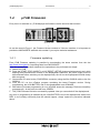
1
ALPHANUMERIC
DISPLAYBOARD
µTAB Light
User Manual
Version 1.1
Microgate S.r.l.
Via Stradivari, 4
I-39100 BOLZANO - ITALY
http://www.microgate.it
µTAB Displayboard
User Manual
⎯⎯⎯⎯⎯⎯⎯⎯⎯⎯⎯⎯⎯⎯⎯⎯⎯⎯⎯⎯⎯⎯⎯⎯⎯⎯⎯⎯⎯⎯⎯⎯⎯⎯⎯⎯⎯⎯⎯⎯⎯⎯⎯⎯⎯⎯⎯
2
µTAB Displayboard
User Manual
3
⎯⎯⎯⎯⎯⎯⎯⎯⎯⎯⎯⎯⎯⎯⎯⎯⎯⎯⎯⎯⎯⎯⎯⎯⎯⎯⎯⎯⎯⎯⎯⎯⎯⎯⎯⎯⎯⎯⎯⎯⎯⎯⎯⎯⎯⎯⎯
INDEX
1
ALPHANUMERIC DISPLAYBOARD µTAB LIGHT (MICROTAB) .................................... 4
1.1
1.2
1.3
1.3.1
1.4
1.4.1
2
C ONTROL P ANEL ......................................................................................................... 5
C ONNECTIONS ............................................................................................................. 6
P OWER S UPPLY ........................................................................................................... 7
Battery Recharge .................................................................................................... 7
µTAB F IR MWAR E ........................................................................................................ 9
Firmware updating .................................................................................................. 9
PROGRAMS .................................................................................................................... 10
2.1
2.2
2.3
2.4
2.5
P ROGRAM 0 (N ORMAL )............................................................................................... 11
P ROGRAM 1 (C HRONOMETER ) ..................................................................................... 12
P ROGRAM 2 (I NTER NAL C LOCK ) .................................................................................. 14
P ROGRAM 3 (T EST ) .................................................................................................... 15
D EFAULT VALUES OF EDITABLE PARAMETERS ................................................................ 16
µTAB Displayboard
User Manual
⎯⎯⎯⎯⎯⎯⎯⎯⎯⎯⎯⎯⎯⎯⎯⎯⎯⎯⎯⎯⎯⎯⎯⎯⎯⎯⎯⎯⎯⎯⎯⎯⎯⎯⎯⎯⎯⎯⎯⎯⎯⎯⎯⎯⎯⎯⎯
1
ALPHANUMERIC
DISPLAYBOARD
µTAB LIGHT
(MICROTAB)
4
µTAB Displayboard
5
User Manual
⎯⎯⎯⎯⎯⎯⎯⎯⎯⎯⎯⎯⎯⎯⎯⎯⎯⎯⎯⎯⎯⎯⎯⎯⎯⎯⎯⎯⎯⎯⎯⎯⎯⎯⎯⎯⎯⎯⎯⎯⎯⎯⎯⎯⎯⎯⎯
1.1
C ONTROL P ANEL
1
2
3
TIMING
4
SERIAL
ON
5
SUPPLY
6
7
1
2
3
4
9
10
5
Green START STOP (MODIFY DISCHARGE/CHARGE) button used for:
• manual START and STOP signals
• editing values of program settings (keep pressed down for fast forward)
• selection of battery discharge and recharge
6 pole Amphenol START-STOP-LAP INPUTS connector for START STOP and LAP signals
Yellow LAP RESET (SETUP DIRECT CHARGE) button used for:
• manual LAP signals and displayboard RESET
• confirmation of program settings
• selection of immediate battery charging
6 pole Amphenol SERIAL connector for serial input/output
LOW BATTERY led to indicate battery status
On/off displayboard POWER switch
7 pole Amphenol SUPPLY connector for external power supply and battery recharge
µTAB Displayboard
6
User Manual
⎯⎯⎯⎯⎯⎯⎯⎯⎯⎯⎯⎯⎯⎯⎯⎯⎯⎯⎯⎯⎯⎯⎯⎯⎯⎯⎯⎯⎯⎯⎯⎯⎯⎯⎯⎯⎯⎯⎯⎯⎯⎯⎯⎯⎯⎯⎯
1.2
C ONNECTIONS
•
SUPPLY (7 pole Amphenol)
1
2
3
4
5
6
7
Ground
Ground
Ground
External supply input (8-25V)
External supply input (8-25V)
External supply input (8-25V)
Remote on/off input
•
SERIAL (6 pole Amphenol)
1
2
3
4
5
6
SERIAL - RS232 TX output
SYNC IN
SERIAL - RS485 + RX input
SERIAL - RS485 – RX input
Ground
SERIAL - RS232 RX input
•
START-STOP-LAP INPUTS (6 pole Amphenol)
1
2
3
4
5
6
Start (NO - Normally Open)
+5V fixed, max 1A
Ground
LAP (NO)
STOP (NO)
Not used
7 pole Amphenol Connector
6 pole Amphenol Connector
µTAB Displayboard
User Manual
7
⎯⎯⎯⎯⎯⎯⎯⎯⎯⎯⎯⎯⎯⎯⎯⎯⎯⎯⎯⎯⎯⎯⎯⎯⎯⎯⎯⎯⎯⎯⎯⎯⎯⎯⎯⎯⎯⎯⎯⎯⎯⎯⎯⎯⎯⎯⎯
1.3
P OWER S UPPLY
Power can be supplied in three ways:
• By connecting the µTAB displayboard to the MICROGATE battery charger. In this way it is
possible to keep the batteries charged at the same time. This guarantees perfect functioning
also when the mains power supply is interrupted.
• By using the internal batteries of the displayboard. In this case autonomy is usually above 30
hours of continuous functioning (depending on the type of display used).
• By connecting the displayboard to any continuous current supply (whether steady or not)
between 10 and 30 Volts which is able to supply at least 30W peak power and about 2W
average power. A car battery guarantees several days’ autonomy.
Important note: the adaptor ACC062 for the µTAB displayboard is not suitable for outdoor use.
Consequently Microgate does not accept any responsibility for damage to persons or things due to
incorrect use of the adaptor.
1.3.1
Battery Recharge
If the batteries are low, either the discharge/recharge or the immediate recharge procedure can be
carried out.
In the first case, the batteries are first discharged and only subsequently recharged. This allows the
batteries to maintain their original capacity over a long period.
To select discharge/recharge, keep the “START STOP (MODIFY CHARGE/DISCHARGE)”
button on the control panel pressed down for at least 2 seconds with the displayboard
switched off after connecting an external power source to the connector SUPPLY. The operation
will take from a minimum 7 hours to a maximum of about 10 hours, depending on the initial battery
charge level.
If you choose immediate recharge instead, the operation will last about 7 hours. However, although
this type of recharge takes less time, it should only be used in exceptional circumstances as it
shortens the life of the batteries.
To select immediate recharge, keep the yellow “LAP RESET (SETUP DIRECT CHARGE)”
button on the control panel pressed down for at least 2 seconds with the displayboard
switched off after connecting an external power source to the connector SUPPLY.
In both recharge modes it is possible to interrupt the process by pressing the START STOP and
LAP RESET keys simultaneously.
µTAB Displayboard
User Manual
8
⎯⎯⎯⎯⎯⎯⎯⎯⎯⎯⎯⎯⎯⎯⎯⎯⎯⎯⎯⎯⎯⎯⎯⎯⎯⎯⎯⎯⎯⎯⎯⎯⎯⎯⎯⎯⎯⎯⎯⎯⎯⎯⎯⎯⎯⎯⎯
The LOW BATTERY led on the control panel tells you the battery charge status, the type of power
source used and the recharge operation status when the battery is being recharged.
EXTERNAL SUPPLY
STATUS
• Displayboard On or Off
• Batteries Charged
• Displayboard On or Off
• Batteries Discharged
LED LOW BATTERY
Green – Green – Pause
Green – Red – Pause
INTERNAL SUPPLY (BATTERY)
STATUS
• Displayboard Off
• Batteries Charged or Discharged
• Displayboard On
• Batteries Charged
• Displayboard On
• Batteries Discharged
LED LOW BATTERY
Off
Green – Pause – Green – Pause
Red – Pause – Red – Pause
CHARGE/DISCHARGE
STATUS
LED LOW BATTERY
Pause – Red – Pause – Red FAST
• Start of Discharging
Pause – Green – Pause – Green FAST
• Discharging Over–Start of Recharging
Green
• Recharging Over
DIRECT CHARGE
STATUS
• Start of Recharging
• Recharging Over
LED LOW BATTERY
Pause – Green – Pause – Green FAST
Green
µTAB Displayboard
9
User Manual
⎯⎯⎯⎯⎯⎯⎯⎯⎯⎯⎯⎯⎯⎯⎯⎯⎯⎯⎯⎯⎯⎯⎯⎯⎯⎯⎯⎯⎯⎯⎯⎯⎯⎯⎯⎯⎯⎯⎯⎯⎯⎯⎯⎯⎯⎯⎯
1.4
µTAB F IRMWARE
Every time it is switched on, µTAB displays the firmware version stored at that moment:
TIPO DI FIRMWARE VERSIONE DEL FIRMWARE
FIRMWARE TYPE
FIRMWARE VERSION
Figure 1
As can be noted in Figure 1, the Firmware Version consists of 2 the two numbers. It is important to
provide the MICROGATE staff with this number if you require technical assistance.
1.4.1
Firmware updating
Free µTAB Firmware updating is possible by downloading the latest versions from the site
http://www.microgate.itor requesting them from MICROGATE.
Once the update file has been obtained, the operations to be performed are simple:
A. Switch off µTAB
B. Press the START STOP (MODIFY) e LAP RESET (SETUP) buttons simultaneously and, while
keeping them pressed down, switch on the displayboard (attention, the power supply must be
disconnected before switching on the displayboard); the led on the displayboard should slowly
blink red-green.
C. Connect the PC serial to the µTAB SERIAL connector (using the 20m CAB010 cable or the 2m
CAB001)
D. From the PC run the uFlasher program containing the latest Firmware version. During
programming, the LOW BATTERY led on the displayboard turns ORANGE.
E. After about 2 minutes programming is over (uFlasher shows the message "Device successfully
programmed"). At this point, the led turns GREEN.
F. The µTAB Firmware has been successfully updated. Now you can switch off the displayboard.
Any error in programming is indicated by the LOW BATTERY led on the displayboard, which turns
RED. In the unlikely eventuality that this should happen, simply repeat the procedure indicated
above.
µTAB Displayboard
User Manual
10
⎯⎯⎯⎯⎯⎯⎯⎯⎯⎯⎯⎯⎯⎯⎯⎯⎯⎯⎯⎯⎯⎯⎯⎯⎯⎯⎯⎯⎯⎯⎯⎯⎯⎯⎯⎯⎯⎯⎯⎯⎯⎯⎯⎯⎯⎯⎯
2
PROGRAMS
µTAB Displayboard
User Manual
11
⎯⎯⎯⎯⎯⎯⎯⎯⎯⎯⎯⎯⎯⎯⎯⎯⎯⎯⎯⎯⎯⎯⎯⎯⎯⎯⎯⎯⎯⎯⎯⎯⎯⎯⎯⎯⎯⎯⎯⎯⎯⎯⎯⎯⎯⎯⎯
2.1
P ROGRAM 0 (N ORMAL )
When run, the μTAB displayboard is set on program 0. In this configuration it is possible to
command µTAB through the SERIAL communication serial port. To change the selected program it
is necessary to enter setup.
Setup
In Program 0 (Normal), setup allows you to re-initialize all µTAB parameters to standard values
and to set the first column displayed on the displayboard.
Keep LAP-SETUP pressed for at least two seconds to enter Setup
Set first
Press LAP-SETUP
program = 0
Set the required program with START-MODIFY
Press LAP-SETUP
column = 0
Set the first column with START-MODIFY
Press LAP-SETUP
Baud = 1200
Set serial communication velocity with START-MODIFY (from 1200 bit/s
to 38400 bit/s (38k4); when setting RAD., instead of using the serial
connection to command µTAB, the Linkgate radio system is used)
Press LAP-SETUP
INT = RS232
Set the interface used for serial connection by using START-MODIFY
(the protocols available are RS232 and RS485)
Press LAP-SETUP
Start to
Press LAP-SETUP
initial.
Press START-MODIFY to confirm, LAP-SETUP to exit without initializing
Sure?
Press START-MODIFY to confirm, LAP-SETUP to exit without initializing
µTAB Displayboard
User Manual
12
⎯⎯⎯⎯⎯⎯⎯⎯⎯⎯⎯⎯⎯⎯⎯⎯⎯⎯⎯⎯⎯⎯⎯⎯⎯⎯⎯⎯⎯⎯⎯⎯⎯⎯⎯⎯⎯⎯⎯⎯⎯⎯⎯⎯⎯⎯⎯
2.2
P ROGRAM 1 (C HRONOMETER )
In this mode µTAB works as a typical chronometer set to 1/100 of a second.
• With Start (manually, from input or via radio) the chronometer starts.
• With Lap (manually, from input or via radio) the chronometer shows an intermediate time
for 5 seconds.
• With manual Start or Stop from input or via radio the chronometer stops.
• Now it is possible to set the chronometer to zero by pressing Lap.
If the chronometer is not set to zero, it will start from the value shown.
If the Autoreset time has been set to follow every Stop (or manual Start), the chronometer resets
itself to zero after the preset time.
NOTE: If the printer is connected, times are printed, coupled to a progressive counter which is
automatically set to zero every time Program 1 (Chronometer) is entered or µTAB is switched off.
Setup
It is possible to set the starting time of the chronometer.
Keep LAP-SETUP pressed for at least two seconds to enter Setup
Set
Press LAP-SETUP
Starttime
Press LAP-SETUP
HH = 0
Set the hours with START-MODIFY
Press LAP-SETUP
MM = 0
Set the minutes with START-MODIFY
Press LAP-SETUP
SS = 0
Set the seconds with START-MODIFY
Press LAP-SETUP
mm = 0
Set the thousandths with START-MODIFY
Press LAP-SETUP
Autoreset
Press LAP-SETUP
Time= 0
Set the automatic Reset time with START-MODIFY (in seconds). A time
of zero disables the Autoreset function.
Press LAP-SETUP
STA-STO
Press START-MODIFY to pass to STA-STA mode. In the latter case
every start event starts and stops the stopwatch.
Press LAP-SETUP
The chronometer is now stopped on the set time, ready to start.
µTAB Displayboard
User Manual
13
⎯⎯⎯⎯⎯⎯⎯⎯⎯⎯⎯⎯⎯⎯⎯⎯⎯⎯⎯⎯⎯⎯⎯⎯⎯⎯⎯⎯⎯⎯⎯⎯⎯⎯⎯⎯⎯⎯⎯⎯⎯⎯⎯⎯⎯⎯⎯
µTAB Displayboard
User Manual
14
⎯⎯⎯⎯⎯⎯⎯⎯⎯⎯⎯⎯⎯⎯⎯⎯⎯⎯⎯⎯⎯⎯⎯⎯⎯⎯⎯⎯⎯⎯⎯⎯⎯⎯⎯⎯⎯⎯⎯⎯⎯⎯⎯⎯⎯⎯⎯
2.3
P ROGRAM 2 (I NTERNAL C LOCK )
This mode allows you to display the time on the µTAB internal clock.
Setup
It is possible to set the time of the internal clock.
NOTE: During time setting, µTAB shows the time at which the setting began. If no value is
modified, the time is not changed and runs as if Setup had not been used.
Keep LAP-SETUP pressed for at least two seconds to enter Setup
Set
Press LAP-SETUP
R.T. Clock
Press LAP-SETUP
HH = 0
Set the hours with START-MODIFY
Press LAP-SETUP
MM = 0
Set the minutes with START-MODIFY
Press LAP-SETUP
SS = 0
Set the seconds START-MODIFY
Press LAP-SETUP
µTAB Displayboard
User Manual
15
⎯⎯⎯⎯⎯⎯⎯⎯⎯⎯⎯⎯⎯⎯⎯⎯⎯⎯⎯⎯⎯⎯⎯⎯⎯⎯⎯⎯⎯⎯⎯⎯⎯⎯⎯⎯⎯⎯⎯⎯⎯⎯⎯⎯⎯⎯⎯
2.4
P ROGRAM 3 (T EST )
Program 3 (Test) is used to check the correct functioning of Pixels: the displayboard becomes
alternately yellow and black. If the displayboard is exposed to temperatures lower than -15°C
before being used, it is advisable to leave it switched on with this program inserted (for example,
outdoors at night in high mountains).
µTAB Displayboard
User Manual
16
⎯⎯⎯⎯⎯⎯⎯⎯⎯⎯⎯⎯⎯⎯⎯⎯⎯⎯⎯⎯⎯⎯⎯⎯⎯⎯⎯⎯⎯⎯⎯⎯⎯⎯⎯⎯⎯⎯⎯⎯⎯⎯⎯⎯⎯⎯⎯
2.5
D EFAULT VALUES OF EDITABLE PARAMETERS
When run, the µTAB displayboard is set on program 0. When µTAB is delivered or after each
global initialization (see 2.1 Program 0 (Normal) p.11), the configurable parameters are
automatically set to the following values (often suitable for many applications):
Program 0 (Normal) page 11
• Column
• Baud
• Frame
• RadCh
0
1200 bit/s
RS232
0
Program 1 (Chronometer) page 12
• Starting Time
0
• Autoreset Time
0
(disabled)
NOTE: Also the time and date are preset to particular values.
To access the required program, follow the instructions given in chap. 2.1 Program 0 (Normal) on
p.11.
Microgate S.r.l.
Via Stradivari, 4
I-39100 BOLZANO - ITALY
http://www.microgate.it