1
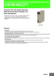
SYSMAC CJ-series Position Control Unit with MECHATROLINK-II interface CJ1W-NC71 CSM_CJ1W-NC_71_DS_E_2_1 Decrease TCO with Simple Operation, Reduced Wiring, Batch Settings, and Batch Management • Control Servos for up to 16 axes in a motion network with one Position Control Unit that supports MECHATROLINK-II ∗. ∗ MECHATROLINK-II is a registered trademark of the MECHATROLINK Members Association. CJ1W-NCF71 Features • Even Smaller Positioning of up to 16 axes can be controlled with a body the size of one CJ-series Unit. The compact body provides a perfect fit to meet the need for downsizing of equipment for multi-axis control. • Single-cable Connection with Flexible Wiring Placement With MECHATROLINK-II, connecting to the Servo Drive is easy. Just use a single cable (2-core shielded twisted-pair cable). Reduced wiring, with a total cable length of 50 m (or 30 m for 16 axes), allows more freedom in constructing systems. • Less Time Spent on Startup and Maintenance Servo parameters can be set from the PLC. This means that settings and adjustments can be performed from one location rather than having to connect to each Servo Drive separately. • Simple Expansion An easily expandable system can be constructed that is just as efficient now with a few axes or later with up to 16 axes. • Linked Operation of Multiple Axes with MA Functionality The addition of an Interpolation Compensation Axis Stop Mode Setting and Interaxial Allowance Deviation Setting to linear interpolation compensation enables easier setting of linked operation between axes. 1 CJ1W-NC71 System Configuration Programmable Terminals NS-series RS-232C Communications (NT Link) Using the CX-Motion-NCF allows all parameters, including Servo Drive parameters, to be transferred at one time. Programmable Controller SYSMAC CJ-series Position Control Unit CJ1W-NC 71 16 axes max. 16 axes max., overall cable length: 100 m(When repeater is used) 100m max. SMARTSTEP Junior AC Servo Drives with Built-in MECHATROLINK-II Communications (R7D-ZN -ML2) Sensors (limit inputs, origin proximity inputs, etc.) AC Servo motor(R7M-Z) OMNUC G5 series OMNUC G series OMNUC W series AC Servo Drive with Built-in MECHATROLINK-II Communications (R88D-KN -ML2) AC Servo motor(R88M-K) AC Servo Drive with Built-in MECHATROLINK-II Communications (R88D-GN -ML2) AC Servo Drives with Built-in MECHATROLINK-II Communications (R88D-WN -ML2) AC Servo motor(R88M-G) AC Servo motor(R88M-W) Connect an FNY-W6022 Terminator to the device at the end of the MECHATROLINK-II network. 2 CJ1W-NC71 Ordering Information International Standards • The standards are abbreviated as follows: U: UL, U1: UL(Class I Division 2 Products for Hazardous Locations), C: CSA, UC: cULus, UC1: cULus (Class I Division 2 Products for Hazardous Locations), CU: cUL, N: NK, L: Lloyd, and CE: EC Directives. • Contact your OMRON representative for further details and applicable conditions for these standards. CJ-series Units Unit type Current No. of unit numbers consumption (A) No. of axes allocated 5V 24 V Specifications Product name Control output interface CJ1 CPU Bus Units Position Control Unit with MECHATROLINK-II interface Control commands executed by MECHATROLINK-II synchronous communications. Direct operation by ladder programming. Control mode: Position control, speed control, or torque control Model 2 CJ1W-NC271 4 CJ1W-NC471 1 0.36 Standards --- UC1, CE 16 CJ1W-NCF71 16 CJ1W-NCF71-MA Support Software Product name FA Integrated Tool Package CX-One Ver. 4. Specifications License The CX-One is a package that integrates the Support Software for OMRON PLCs and components. CX-One runs on the following OS. Windows 2000 (Service Pack 4 or higher), XP, Vista, or 7 Note: Except for 64-bit version. Media Model CD CXONE-AL01C-V4 Standards 1 license ∗ --DVD CX-One Ver. 4. includes CX-Motion-NCF Ver. 1.. For details, refer to the CX-One catalog (Cat. No. R134). CXONE-AL01D-V4 ∗ Site licenses are available for the CX-One (3, 10, 30, or 50 licenses). MECHATROLINK-related Devices and Cables (Manufactured by Yaskawa Corporation) Name OMRON model number MECHATROLINK-II Interface Unit For W-series Servo Driver MECHATROLINK-II Cables (with ring core and USB connector on both ends) MECHATROLINK-II Terminating Resistor MECHATROLINK-II Repeater Yaskawa model number FNY-NS115 JUSP-NS115 0.5 m FNY-W6003-A5 JEPMC-W6003-A5 1.0 m FNY-W6003-01 JEPMC-W6003-01 3.0 m FNY-W6003-03 JEPMC-W6003-03 5.0 m FNY-W6003-05 JEPMC-W6003-05 10.0 m FNY-W6003-10 JEPMC-W6003-10 20.0 m FNY-W6003-20 JEPMC-W6003-20 30.0 m FNY-W6003-30 JEPMC-W6003-30 Terminating resistance Communications Repeater FNY-W6022 JEPMC-W6022 FNY-REP2000 JEPMC-REP2000 Note: MECHATROLINK-related Devices and Cables are manufactured by Yaskawa Corporation, but they can be ordered directly from OMRON using the OMRON model numbers. (Yaskawa-brand products will be delivered even when they are ordered from OMRON.) Accessories None Mountable Racks CJ system (CJ1, CJ2) Model CPU Rack CJ1W-NC71 (-MA) Expansion Backplane 16 Units max. (10 per Rack) CP1H system NSJ system CP1H PLC NSJ Controller Expansion Backplane 2 Units ∗ Not supported 10 Units ∗ A CP1W-EXT01 CJ Unit Adaptor is required. 3 CJ1W-NC71 Specifications General Specifications Item Specifications Model CJ1W-NC271/471/F71 (-MA) Internal current consumption 360 mA max. at 5 V DC Dimensions 31 × 90 × 65 mm (W × H × D) Weight 95 g max. Ambient operating temperature 0 to 55°C Approved standards CE, cULus, and C-tick Specifications not listed above conform to general CJ Series specifications. Functions and Specifications Item Specifications Unit classification CPU Bus Unit Applicable PLCs CJ Series Possible unit number settings 0 to F Common Operating Memory Area Words allocated in CPU Bus Unit Area: 25 words (15 output words, 10 input words) Axis Operating Memory Area Allocated in one of the following areas (user-specified): CIO, Work, Auxiliary, Holding, DM, or EM Area. Number of words allocated: 50 words (25 output words, 25 input words) × Highest axis No. used I/O allocations Compatible devices • OMRON G5-series Servo Drives (Built-in MECHATROLINK-II communications) • OMRON G-series Servo Drives (Built-in MECHATROLINK-II communications) • OMRON W-series Servo Drives (equipped with MECHATROLINK-II Interface Unit or built-in MECHATROLINK-II communications) • OMRON SMARTSTEP Junior Servo Drives (Built-in MECHATROLINK-II communications) ∗ Control method Control commands executed using MECHATROLINK-II synchronous communications. Maximum number of controlled axes CJ1W-NC271: 2 axes, CJ1W-NC471: 4 axes, CJ1W-NCF71: 16 axes Control units Position command unit Command unit: Depends on the Electronic Gear Setting in the Servo Parameters. Default setting: Pulses Speed command unit for position control Command units/s Acceleration/deceleration speeds for position control 10,000 command units/s2 Speed command unit for speed control 0.001% of the motor's momentary maximum rotation speed Torque command unit for torque control 0.001% of the motor's momentary maximum torque Position command range -2,147,483,648 to 2,147,483,647 (command units) Speed command range for posi0 to 2,147,483,647 (command units/s) tion control Control command range Control functions Acceleration/deceleration speeds for position control 1 to 65,535 (10,000 command units/s2) Speed command range for speed control -199.999% to 199.999% The upper limit of the speed command range depends on the specifications of the Servo Drive. Torque command range for torque control -199.999% to 199.999% The upper limit of the torque command range depends on the specifications of the Servo Drive. Servo lock/unlock Creates (Servo lock) or releases (Servo unlock) the position loop on the PCU. Position control Positions to an absolute position or relative position according to the target position and target speed specified from the ladder program. Origin determination • • • • Jogging Outputs pulses at a fixed speed in the forward rotation or reverse rotation direction. Interrupt feeding Performs positioning by moving the axis a fixed amount when an external interrupt input is received while the axis is moving. Speed control Performs speed control by sending a command to the Servo Drive speed loop. Torque control Performs torque control by sending a command to the Servo Drive current loop. Stop functions • Deceleration stop: Decelerates the moving axis to a stop. • Emergency stop: Positions the moving axis for the number of pulses remaining in the deviation counter and then stops the axis. Origin search: Establishes the origin using the specified search method. Present position preset: Changes the present position to a specified position to establish the origin. Origin return: Returns the axis from any position to the established origin. Absolute encoder origin: Establishes the origin using a Servomotor that has an absolute encoder, without having to use an origin search. 4 CJ1W-NC71 Item Auxiliary functions External I/O Specifications Acceleration/deceleration curves Sets one of the following: a trapezoidal (linear) curve, an exponential curve, or an S-curve (moving average). Torque limit Restricts the output torque during axis operation. Override Multiplies the axis command speed by a specified ratio. Override: 0.01% to 327.67% Servo parameter transfer Reads and writes the Servo Drive parameters from the ladder program in the CPU Unit. Monitoring function Monitors the control status of the Servo Drive, such as the command coordinate positions, feedback position, current speed, and torque. Software limits Limits software operation within the positioning range during position control. Backlash compensation Compensates for the amount of play in the mechanical system according to a set value. Deviation counter reset The position deviation in the Servo Drive’s deviation counter can be reset to 0 (unit version 1.3 or later). Position Control Unit One MECHATROLINK-II interface port Servo Drive I/O Forward/reverse rotation limit inputs, origin proximity inputs, external interrupt inputs 1 to 3 (can be used as external origin inputs) Self-diagnostic functions Watchdog, flash memory check, memory corruption check Error detection functions Overtravel, Servo Drive alarm detection, CPU error, MECHATROLINK communications error, Unit setting error ∗ SMARTSTEP Junior Servo Drive are supported by Position Control Units with unit version 2.0 or later. MECHATROLINK Specifications Item Specifications Communications protocol MECHATROLINK-II Baud rate 10 Mbps Maximum transmission distance 50 m ∗1 Minimum distance between stations 0.5 m Transmission media Shielded, twisted-pair cables Maximum No. of stations 30 slave stations max. ∗2 Topology Bus Transfer cycle 250 µs to 8 ms Communications method Master-slave, totally synchronous Encoding Manchester encoding Data length 17 bytes/32 bytes selectable ∗3 ∗1. This distance is the total length of the cable connected between devices. However, the maximum length depends on the number of devices connected and whether Repeaters are used. ∗2. Up to 16 devices can be connected to the CJ1W-NCF71 (-MA), up to 2 devices can be connected to the CJ1W-NC271, and up to 4 devices can be connected to the CJ1W-NC471. ∗3. The PCU data length is fixed at 32 bytes. 5 CJ1W-NC71 External Interface CJ1W-NC71 (-MA) NCF71 RUN ERC ERH ERM MLK 789A F 012 BCDE LED Indicators Indicate the PCU's operating status. UNIT No. Unit Number Setting Switch Sets the PCU's unit number. MECHATROLINK-II Communications Connector Connects to the MECHATROLINK-II Connection Cable. 3456 MLK LED Indicators LED RUN Name Run Color Green Status Lit Not lit Lit ERC Unit Error Red Flashing Not lit ERH CPU Unit Error Red ERM MECHATROLINK Device Error Red Lit Not lit Lit Flashing Not lit MLK MECHATROLINK Communications Status Yellow Lit Not lit Details The PCU is operating normally. Other condition A fatal error has occurred in the PCU and operation cannot continue. A non-fatal error has occurred in the PCU and operation can continue. Other condition An error has occurred in the PLC. Other condition An error has occurred in MECHATROLINK communications. An error has occurred in a connected MECHATROLINK device. Other condition MECHATROLINK communications in progress MECHATROLINK communications stopped 6 CJ1W-NC71 Functions Supported According to Position Control Unit Versions CJ1W-NC71 (-MA) Model Unit Ver. 1.0 Unit Ver. 1.1 Unit Ver. 1.2 Unit Ver. 1.3 Unit Ver. 2.0 Unit Ver. 2.1 Linear interpolation --- Supported. Supported. Supported. Supported. Supported. Absolute encoder setup function --- --- Supported. Supported. Supported. Supported. Deviation counter reset --- --- --- Supported. Supported. Supported. Establishing connections even when there are unconnected axes or axes with alarms that cannot be cleared --- --- --- Supported. Supported. Supported. Transferring servo parameters even when there is an axis error --- --- --- Supported. Supported. Supported. Creating servo locks during software limit detection when an absolute encoder is used --- --- --- Supported. Supported. Supported. Driver main circuit OFF error detection only when the servo is locked --- --- --- Supported. Supported. Supported. Using Holding Area address H512 and onwards for function block address allocations --- --- --- Supported. Supported. Supported. Addition of supported models: SMARTSTEP Junior Servo Drives (R7D-ZN-ML2) --- --- --- --- Supported. Supported. Addition of rejoin function --- --- --- --- Supported. Supported. Eliminating connection restriction when Servo Drive alarms occur (enabling connection when alarm A.C90 occurs) --- --- --- --- Supported. Supported. Addition of origin search operation modes --- --- --- --- Supported. Supported. Addition of origin search preset function --- --- --- --- Supported. Supported. Faster setting for transfer cycle and communications cycle when setting the absolute encoder PG zero point position offset with an origin search --- --- --- --- --- Supported. Dimensions (Unit: mm) CJ1W-NC271 CJ1W-NC471 CJ1W-NCF71 CJ1W-NCF71-MA 31 2.7 65 NCF71 RUN ERC ERH ERM MLK 789A F 012 D BC E UNIT No. 3456 90 MLK 2.7 Related Manuals Engilsh Cat.No. Japanese Cat.No. Model Name W426 SBCE-323 CS1W-NC71/ CJ1W-NC71(-MA) CS1W/CJ1W-NC71(-MA) CS/CJ-series MECHATROLINK-II-compatible Postion Controll Unit User's Manual W436 SBCE-328 CXONE-ALC/D-V CX-Motion-NCF Operation Manual --- SBCE-055 CS1W-NCF71/CJ1W-NCF71 CS1W-NCF71/CJ1W-NCF71 Position Controll Unit(ONNUC G-series)Technical Guide --- SBCE-042 CS1W-NCF71/CJ1W-NCF71 CS1W-NCF71/CJ1W-NCF71 Position Controll Unit(ONNUC W-series)Technical Guide 7 Read and Understand This Catalog Please read and understand this catalog before purchasing the products. Please consult your OMRON representative if you have any questions or comments. Warranty and Limitations of Liability WARRANTY OMRON's exclusive warranty is that the products are free from defects in materials and workmanship for a period of one year (or other period if specified) from date of sale by OMRON. OMRON MAKES NO WARRANTY OR REPRESENTATION, EXPRESS OR IMPLIED, REGARDING NON-INFRINGEMENT, MERCHANTABILITY, OR FITNESS FOR PARTICULAR PURPOSE OF THE PRODUCTS. ANY BUYER OR USER ACKNOWLEDGES THAT THE BUYER OR USER ALONE HAS DETERMINED THAT THE PRODUCTS WILL SUITABLY MEET THE REQUIREMENTS OF THEIR INTENDED USE. OMRON DISCLAIMS ALL OTHER WARRANTIES, EXPRESS OR IMPLIED. LIMITATIONS OF LIABILITY OMRON SHALL NOT BE RESPONSIBLE FOR SPECIAL, INDIRECT, OR CONSEQUENTIAL DAMAGES, LOSS OF PROFITS OR COMMERCIAL LOSS IN ANY WAY CONNECTED WITH THE PRODUCTS, WHETHER SUCH CLAIM IS BASED ON CONTRACT, WARRANTY, NEGLIGENCE, OR STRICT LIABILITY. In no event shall the responsibility of OMRON for any act exceed the individual price of the product on which liability is asserted. IN NO EVENT SHALL OMRON BE RESPONSIBLE FOR WARRANTY, REPAIR, OR OTHER CLAIMS REGARDING THE PRODUCTS UNLESS OMRON'S ANALYSIS CONFIRMS THAT THE PRODUCTS WERE PROPERLY HANDLED, STORED, INSTALLED, AND MAINTAINED AND NOT SUBJECT TO CONTAMINATION, ABUSE, MISUSE, OR INAPPROPRIATE MODIFICATION OR REPAIR. Application Considerations SUITABILITY FOR USE OMRON shall not be responsible for conformity with any standards, codes, or regulations that apply to the combination of products in the customer's application or use of the products. At the customer's request, OMRON will provide applicable third party certification documents identifying ratings and limitations of use that apply to the products. This information by itself is not sufficient for a complete determination of the suitability of the products in combination with the end product, machine, system, or other application or use. The following are some examples of applications for which particular attention must be given. This is not intended to be an exhaustive list of all possible uses of the products, nor is it intended to imply that the uses listed may be suitable for the products: • Outdoor use, uses involving potential chemical contamination or electrical interference, or conditions or uses not described in this catalog. • Nuclear energy control systems, combustion systems, railroad systems, aviation systems, medical equipment, amusement machines, vehicles, safety equipment, and installations subject to separate industry or government regulations. • Systems, machines, and equipment that could present a risk to life or property. Please know and observe all prohibitions of use applicable to the products. NEVER USE THE PRODUCTS FOR AN APPLICATION INVOLVING SERIOUS RISK TO LIFE OR PROPERTY WITHOUT ENSURING THAT THE SYSTEM AS A WHOLE HAS BEEN DESIGNED TO ADDRESS THE RISKS, AND THAT THE OMRON PRODUCTS ARE PROPERLY RATED AND INSTALLED FOR THE INTENDED USE WITHIN THE OVERALL EQUIPMENT OR SYSTEM. PROGRAMMABLE PRODUCTS OMRON shall not be responsible for the user's programming of a programmable product, or any consequence thereof. Disclaimers CHANGE IN SPECIFICATIONS Product specifications and accessories may be changed at any time based on improvements and other reasons. It is our practice to change model numbers when published ratings or features are changed, or when significant construction changes are made. However, some specifications of the products may be changed without any notice. When in doubt, special model numbers may be assigned to fix or establish key specifications for your application on your request. Please consult with your OMRON representative at any time to confirm actual specifications of purchased products. DIMENSIONS AND WEIGHTS Dimensions and weights are nominal and are not to be used for manufacturing purposes, even when tolerances are shown. PERFORMANCE DATA Performance data given in this catalog is provided as a guide for the user in determining suitability and does not constitute a warranty. It may represent the result of OMRON’s test conditions, and the users must correlate it to actual application requirements. Actual performance is subject to the OMRON Warranty and Limitations of Liability. ERRORS AND OMISSIONS The information in this document has been carefully checked and is believed to be accurate; however, no responsibility is assumed for clerical, typographical, or proofreading errors, or omissions. 2010.4 In the interest of product improvement, specifications are subject to change without notice. OMRON Corporation Industrial Automation Company http://www.ia.omron.com/ (c)Copyright OMRON Corporation 2010 All Right Reserved.