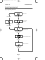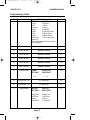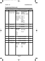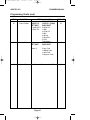
1
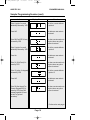
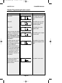
580 Eng PR2945.QXD
07/03/01
16:19
Page 1
GARDTEC
5 0 0
S E R I E S
GARDTEC 580
Installation Instructions
580 Eng PR2945.QXD
07/03/01
16:19
Page 3
GARDTEC 580
ENGINEERS MANUAL
Contents
Introduction
1
Planning the Control Panel Location
Installation
Cable Entries
Mains Supply Connection
Terminal Block Connections
Output Terminal Descriptions
Remote Keypad
Digigard Communicator Interface
Initial Power Up
2
2
3
4
5
6
8
8
9
Reset to Default Modes
9
System Programming
Programming Charts
10
12
Sample programming Session
15
Engineer Modes
Setting the System
Removing Zones
Testing the System
Viewing the Log
Setting Chime On/Off
Changing Engineer Codes
19
20
21
22
23
24
25
Resetting After an Alarm
26
Programmable Options Description
27
Display Messages
System
Status
Log
30
30
31
Fault Finder
32
Specification
34
Zone Type Terminology
35
580 Eng PR2945.QXD
07/03/01
16:19
Page 4
GARDTEC 580
ENGINEERS MANUAL
Introduction
The Gardtec 580 Control Panel is a seven zone microprocessor based unit that has
been designed to be suitable for domestic and small commercial installations. All
zones are fully programmable by the engineer.
Upon completion of the installation the engineer may, if need be, re-program several
factory set options so as to tailor the Control Panel to suit the requirements of the system.
It should be noted that if a new four digit engineer code starts with a 9 it will be
locked into the system and may only be changed by using the code again
(default to factory settings will have no effect). This gives you the ability to protect your service revenue.
The Control Panel is supplied complete with an onboard keypad. Upto four remote keypads may be fitted if required. If remote keypads are used one extra entry / exit zone
may be used from the terminals within one of the keypads
All detection and output wiring is taken directly to the Control Panel, which also incorporates a 220/240V a.c connection. A transformer and adequate space for a rechargeable lead acid battery upto 7 ampere/hour is also provided.
Display of the system status is given via a twin seven segment L.E.D display on the
Control Panel. This display is also echoed on all remote keypads that are fitted. The
twin seven segment display has the ability to give more logical information to the user.
Keypress tamper is factory set to 24 digits (without a valid code number) before the
tamper is activated. During unset conditions this will cause an internal alarm and during a set condition it will cause a full alarm.
We recommend that this engineers manual and the user manual are read and fully
understood before any installation of the system is carried out. You will find that a little
time spent now understanding the product will be a great time saver for the future.
Page 1
580 Eng PR2945.QXD
07/03/01
16:19
Page 5
GARDTEC 580
ENGINEERS MANUAL
Planning the Control Panel Location
Consideration in locating the fixing position of the Control Panel should be given to:
The underside position of the lid securing screw with relation to the cover
fitting and removal.
Access for the routing of cables for the system from detection devices,
sounders (internal and external), remote keypads, mains, etc.
The fixing of a 3 amp unswitched fused spur.
Operation of the onboard keypad.
Readability of the display.
Installation
Slacken the cover screw located on the lower edge of the Control Panel but do not
remove completely.
Pull the lower edge of the cover forward and upwards in one movement. Store cover in
a safe place.
Although the main P.C.B (Printed Circuit Board) is protected by the plastic moulding
we would recommend that it is removed until the rear portion of the Control Panel is
fixed to the wall.
To do this remove the speaker wires from the terminal block. Unclip the P.C.B from
one of the side clips and lift clear of the other side clip with a sidewards motion. Unplug
the a.c/battery connection from the underside of the P.C.B. Store the P.C.B in a safe
place.
Mark the fixing position on the wall (one upper hanger and two fixing holes) using the
Control Panel backplate as a template. Under no circumstances should you drill whilst
holding the backplate in position.
Fix to the wall using appropriate wall plugs and No.8 screws at least 30mm long. Do
not tighten the screws at this stage, wait until all your wiring is in place.
Page 2
580 Eng PR2945.QXD
07/03/01
16:19
Page 6
GARDTEC 580
ENGINEERS MANUAL
Cable Entries
The cable entries can be seen in Fig 1. below. It should be noted that when the larger
of the two cable entry slots below the speaker housing is used the cables will tend to
lie flat and side by side. This will make the task of tightening the fixing screws and getting the panel to 'lie flat' to the wall easier.
Fig 1. GARDTEC 580 Backplate.
D
D
J
L
E
N
B
A
N
B
F
D
B
L
M
D
B
C
P
K
Digigard Position
E
E
E
H
G
G
G
KEY:
A = Mains entry
H = Cover fixing screw
B = Low voltage cable entry x4
J = Speaker enclosure
C = Mains connector
K = Transformer
D = P.C.B Supports x4
L = P.C.B Retaining clips
E = Fixing screw holes x4
M = Rear tamper switch position
F = Fixing screw hanger
N =Digigard retaining lugs x2
G = Battery Retaining Lugs
P = Spare fuse holder
Page 3
580 Eng PR2945.QXD
07/03/01
16:19
Page 7
GARDTEC 580
ENGINEERS MANUAL
Mains Supply Connection
A 220/240V a.c supply should be taken directly from the consumer unit. In order to
comply with the requirements of B.S 4737 this should be via a 3 Amp unswitched fused
spur. This is shown in Fig 2. below.
Fig 2. Mains Supply Connection
Consumer Unit
Off
Connections:
On
Live = Red
Earth = Green/Yellow
Neutral = Black
3A Unswitched
Spur
L
E
N
Page 4
580 Eng PR2945.QXD
07/03/01
16:19
Page 8
GARDTEC 580
ENGINEERS MANUAL
Terminal Block Connections
Fig 3. below shows the connections for a typical system.
+
SPEAKER
SPKR
-
PROGRAMMABLE SW+ TO LATCH TERMINALS ON GARDSCANS, SHOCKGARDS ETC
PGM1
PGM2
PROGRAMMABLE OUTPUT TO DETECTORS
REQUIRING + REMOVE TO RESET
12V
DETECTOR
SUPPLY
+
AUX 12V
+
STROBE
LIGHT
STROBE
+
BELL
S.A.B
MODULE
BELL HOLD SAB TAMP
+
AZ1
N/C DEVICES
N/O DEVICE
+
AZ2
N/C DEVICES
+
N/O DEVICE
AZ3
N/C DEVICES
+
AZ4
N/C DEVICES
-
+
AZ5
N/C DEVICES
+
AZ6
N/C DEVICES
+
AZ7
N/C DEVICES
+
TAMP
N/C TAMPER LOOP
D IN
D IN
REMOTE
KEYPAD
4 wire
(MAX 4)
D OUT
REMOTE
KEYPAD
4 wire
D OUT
IN
DATA
OUT
12V
12V
+
0V
0V
-
AUX 12V
Page 5
580 Eng PR2945.QXD
07/03/01
16:19
Page 9
GARDTEC 580
ENGINEERS MANUAL
Output Terminal Descriptions
Speaker Terminals
One speaker is fitted as standard to the GARDTEC 580 and a speaker is supplied in
each keypad. If an extension speaker is required it should have a minimum impedance
of 16 . Both of the speakers should be wired in series format as shown in Fig 4.
Fig 4. 2 x Speakers
Coarse adjustment
of the low volume
tones is achieved
through adjustment
of the onboard
potentiometer situated to the right of
fuse F2 on the PCB
edge. Fine adjustment is via the software option
'Sounder Levels'
Speaker 2
16
(Extension)
Speaker 1
(Panel)
+
SPKR
PGM 1 Terminal
This terminal provides the switch +ve (or set +ve) required by most types of latching
detectors. The terminal is an open collector output held at 12V through an integral 1k
resistor. Max current sink into this terminal is 50mA. This terminal is programmable for
other uses (as shown in PGM2) if required.
PGM 2 Terminal
This terminal provides a switched 12V output and is programmable by the engineer
from the list below. The terminal would normally be used with latching detectors that
require the power to be removed to reset. Max current source from this terminal is
50mA
PGM Options
Pulse On
Switch +ve
(set +ve)
Pulse Off
Bell
Strobe
Exit / Entry
Test
Int Alarm
A more detailed description is given in the programmable options description.
Page 6
580 Eng PR2945.QXD
07/03/01
16:19
Page 10
GARDTEC 580
ENGINEERS MANUAL
Output Terminal Descriptions (cont)
Power Supply Rating
It should be noted that the Gardtec 580 has 1 Amp available for the full system.
Sounders, detectors and other auxiliary items should be included when calculating current drawn by the system. Any damage caused through overloading the
Control Panel will not be covered by the warranty.
AUX 12V Terminals
This pair of terminals supply the + and - supply for detectors such as Gardscan P.I.Rs,
Shockgard vibration sensors, etc. 1 Amp is available from these terminals (see power
supply rating above).
Strobe Terminals
This pair of terminals are the output for the strobe light. The negative terminal is
switched during an alarm period. It should be noted that after an alarm, the strobe will
overrun after the bell has reset until the system is unset. A maximum of 500mA may be
drawn from these terminals (see power supply rating above).
Bell Terminals
This pair of terminals are the output for the Bell or external sounder. The negative terminal is switched during an alarm period. A maximum of 1 Amp may be drawn from
these terminals (see power supply rating above).
Page 7
580 Eng PR2945.QXD
07/03/01
16:19
Page 11
GARDTEC 580
ENGINEERS MANUAL
Remote Keypads
Upto four remote keypads may be fitted to the GARDTEC 580 control panel. The
GARDTEC 580 LED RKP has a twin seven segment display, backlit keypad and an
integral speaker.
One extra Entry / Exit zone may be used from any one of the RKPs increasing the
number of available zones to eight. Terminals to facilitate both the extra zone and
associated tamper are included within the remote keypad.
A four core connection will be required between the control panel data port and remote
keypad(s), we would advise that all keypads are in a 'daisy chain' format.
Full instructions for connection are included with the RKPs.
ProDigi Communicator
The ProDigi communicator may be fitted to the GARDTEC 580 Series control. A four
core connection will be required to the control panel data port. The ProDigi must be the
first device in the 'daisy chain' line between the control panel and any other remote
devices.
The ProDigi will require programming from a GARDTEC 800 Series control panel or a
ProDigi programmer. A ProDigi programmer is available at all Gardiner Technology
branches for customer use.
Page 8
580 Eng PR2945.QXD
07/03/01
16:19
Page 12
GARDTEC 580
ENGINEERS MANUAL
Initial Power Up
When the Control Panel is initially powered up it will be either set or unset dependent
on the state of the Control Panel when it was powered down. The factory default state
will be unset.
As power is applied segments of the twin seven segment display will be lit for approx
six seconds. During this period press 4 6 YES NO to ensure that the Control Panel is
at factory settings. The display will then show set or unset.
Reset to Default Modes
Two methods may be used to reset the Control Panel back to factory defaults.
Method 1
Remove the cover from the Control Panel (this will cause a tamper Cb on display and
sounder).
Remove the link marked LK1 on the edge of the P.C.B module (this will give temporary
access to the default codes 5678 for user and 1234 for engineer)
Enter the factory default user code 5678 to stop the sounder.
If you wish to re-program the user code, enter this code again to enter user mode
and follow the user instructions for changing user codes. You must replace LK1
before you enter the new code.
Or if you wish to re-program an engineer option, enter the factory default engineer
code (1234) and press YES to gain access. Then replace LK1 and follow the engineer
programming instructions.
Method 2
Apply power to the panel and press 00 within the first 5 seconds.
Down power the again and leave for at least 10 seconds.
Re-apply either the mains or battery supply.
Press 4 6 YES NO within the first 5 seconds.
The Control Panel is now back to factory defaults.
Note: The two methods shown above will have no effect on the engineer code if
it started with a '9'. If this is the case, only re-use of the programmed engineer
code will allow it to be changed.
Page 9
580 Eng PR2945.QXD
07/03/01
16:19
Page 13
GARDTEC 580
ENGINEERS MANUAL
System Programming
The system may be programmed by the engineer by use of the engineer code (1234
factory default). Other functions are also available to the engineer, these are as follows.
Set
The engineer may fully set the system or partset the system.
Unset
The engineer may only unset the system using the engineer code if it has previously
been set using the engineer code.
Remove
The engineer may remove individual zones when setting the system.
Test
The engineer may use this function to test the system.
Log
Using this function the engineer may read the log. The log will be shown on a last
event first basis.
Chime
Using this function the engineer may turn the chime function on and off. It should be
noted that chime zones must first be programmed from the engineer zone option.
The above options will be dealt with in the section Engineer Modes
Fig 6. shows the flow chart to be used when programming the GARDTEC 580
Page 10
580 Eng PR2945.QXD
07/03/01
16:19
Page 14
GARDTEC 580
ENGINEERS MANUAL
System Programming (cont)
Fig 6. Programming Flow Chart
System is Unset
Press 0 (quit)
Enter engineer Code
Do you wish to use
engineer mode
Option to set
Press YES
Press 0 (quit)
This is engineer mode
Enter option number
then YES
This is the existing option value
Press NO
Enter new value here
Enter new value
then YES
Page 11
580 Eng PR2945.QXD
07/03/01
16:19
Page 15
GARDTEC 580
ENGINEERS MANUAL
Programming Charts
MENU
No
1
FUNCTION
Zone1 Attributes
OPTIONS AVAILABLE
LEFT DIGIT
RIGHT DIGIT
0=12Hr
0=Full Set
1=E/E
1=Part1
2=Access
2=Part2
3=Panic
3=Part1&2
4=24Hr
4=Full Set+Chime
5=Fire
5=Part1+Chime
6=Alert
6=Part2+Chime
7=Exit Term
7=Part 1&2+Chime
8=Part E/E
The terminology used for zone types is
given on page 35
2
Zone 2 Attributes
As Zone1 Options
80
3
Zone 3 Attributes
As Zone1 Options
00
4
Zone 4 Attributes
As Zone1 Options
01
5
Zone 5 Attributes
As Zone1 Options
02
6
Zone 6 Attributes
As Zone1 Options
00
7
Zone 7 Attributes
As Zone1 Options
30
8
Sounder Level
CHIME
LEFT DIGIT
ENTRY/EXIT
RIGHT DIGIT
0-9
DEFAULT
14
55
0-9
9
Full Set Exit Time
00 - 99seconds
30
10
Part Set Exit Time
00 - 99seconds
30
11
Setting Modes
FULL SET
LEFT DIGIT
PART SET
RIGHT DIGIT
0=Exit Term
1=E/E Door
2=Time
3=Time+E/E
0=Exit Term
1=E/E Door
2=Time
3=Time+E/E
Page 12
22
580 Eng PR2945.QXD
07/03/01
16:19
Page 16
GARDTEC 580
ENGINEERS MANUAL
Programming Charts (cont)
MENU
No
12
FUNCTION
OPTIONS AVAILABLE
Part Set Sounders PART
& Output 1 Mode SOUNDERS
LEFT DIGIT
PROGRAMMABLE
OUTPUT 1
RIGHT DIGIT (PGM1)
DEFAULT
31
0=All Parts silent 0=Pulse On
1=Part 2 silent
1=SW+
2=Parts1&3 silent 2=Pulse Off
3=All Parts
3=Bell
Audible
4=Strobe
5=Entry/Exit
6=Test
7=Int. Alarm
13
Entry Time 1
00 - 99seconds
30
14
Entry Time 2
00 - 99seconds
10
15
Keypad
ALERT KEYS
LEFT DIGIT
0=Off
1=Panic
2=Fire
3=Alert
10
RIGHT DIGIT
Always 0
16
Bell Re-Arms
00 Re-Arms - 99 Re-Arms
99
17
Bell Ring Time
00 minutes - 99 minutes
20
18
Bell Delay Time
00 minutes - 99 minutes
00
19
Bell Mode
BELL TYPE
LEFT DIGIT
TAMPER RING
RIGHT DIGIT
0=SAB
1=SCB
0=Off
1=On
Page 13
00
580 Eng PR2945.QXD
07/03/01
16:19
Page 17
GARDTEC 580
ENGINEERS MANUAL
Programming Charts (cont)
MENU
No
20
FUNCTION
P.A and
Output 2 Mode
21
Reset Modes
OPTIONS AVAILABLE
PROGRAMMABLE
SILENT P.A
OUTPUT 2 (PGM2)
LEFT DIGIT
RIGHT DIGIT
0= Audible P.A 0=Pulse On
1= Silent P.A
1=SW+
2=Pulse Off
3=Bell
4=Strobe
5=Entry/Exit
6=Test
7=Int. Alarm
RESET MODE
LEFT DIGIT
RIGHT DIGIT
Always 0
22
Service Timer
02
00
0=Any Code
1=Master Code
2=Anti-Code
3=Engineer Code
00weeks - 98weeks.
Page 14
DEFAULT
99 = Off
99
580 Eng PR2945.QXD
07/03/01
16:19
Page 18
GARDTEC 580
ENGINEERS MANUAL
Sample Programming Session
In this sample programming session we will see how to change the following options.
Change zone 3 to be an Entry/Exit zone with chime.
Change zone 4 to be a part Entry/Exit zone, full set
Change zone 6 so it is removed (omitted) when the system is part 1 set.
Change keypad alert keys to Fire
Change bell on time to 15 minutes.
Change the engineer code (1234) to 2580. Note: If your new engineer code starts
with a '9' resetting the unit back to factory defaults will not reset the engineer
code.
Action
Display Shows
Result
The system is Unset
Enter the Engineer Code
Do you want to use
Engineer mode
Press YES
This is Engineer mode
(waiting for an option number)
Enter 3 (option for zone3
attributes) followed by YES
This is the current attribute
for option 3
Press NO
This allows a new value to
be entered.
Enter 14 (E/E Full set +
Chime) followed by YES
Note we will turn the chime
function ON later
This has now returned us to
the point where an option
number is entered
Continued on next page>
Page 15
580 Eng PR2945.QXD
07/03/01
16:19
Page 19
GARDTEC 580
ENGINEERS MANUAL
Sample Programming Session (cont)
Action
Display Shows
Result
Enter 4 (option for zone4
attributes) followed by YES
This is the current attribute
for option 4
Press NO
This allows a new value to
be entered.
Enter 80 (Part E/E Full set)
followed by YES
This has now returned us to
the point where an option
number is entered
Enter 6 (option for zone6
attributes) followed by YES
This is the current attribute
for option 6
Press No
This allows a new value to
be entered.
Enter 01 (12Hr Part1) followed by YES
This has now returned us to
the point where an option
number is entered
Enter 15 (option for keypad)
followed by YES
This is the current attribute
for option 15
Press NO
This allows a new value to
be entered.
Enter 20 (Alert keys=Fire
Remote Keypad=Off) followed by YES (keys 1&3
pressed together will now
act as Fire (pulsed
sounders).
This has now returned us to
the point where an option
number is entered
Continued on next page>
Page 16
580 Eng PR2945.QXD
07/03/01
16:19
Page 20
GARDTEC 580
ENGINEERS MANUAL
Sample Programming Session (cont)
Action
Display Shows
Result
Enter 17 (option for Bell
Ring Time) followed by YES
This is the current attribute
for option 17
Press NO
This allows a new value to
be entered.
Enter 15 (the new time in
minutes) followed by YES
This has now returned us to
the point where an option
number is entered
The Engineer code is not
programmed from this
mode. To gain access to
the Engineer code option
Press 0 (Quit)
This is asking do you want
to set the system
Press NO
This is asking do you want
to remove zones
Press NO
This is asking do you want
to test the system
Press NO
This is asking do you want
to view the log
Press NO
This is asking do you want
to turn the chime ON or
OFF
Press YES
This is showing the chime
function is turned OFF
Press NO
The chime function is now
turned ON
Page 17
580 Eng PR2945.QXD
07/03/01
16:19
Page 21
GARDTEC 580
ENGINEERS MANUAL
Sample Programming Session (cont)
Action
Display Shows
Result
Press YES
This is asking do you want
to turn chime ON or OFF
again
Press NO
This is asking do you want
to program user code (in
this case engineer)
Press YES
This is asking for a new
engineer code
Enter your new code (digits
will show on display as you
enter them). Followed by
YES. If first digit is 9 code
will be locked into system
(see page 1).
This is asking you to repeat
your new code
Re-Enter your new code followed by YES. A comfort
tone will be generated each
time the YES key is
pressed to show that all is
O.K. If no tone is generated
a mistake has been made
or the codes do not match.
In cases were no tone is
generated the code will not
be updated.
This is asking if you wish to
program the engineer code
again.
We have now finished this
programming session.
Press 0 (quit) to return the
system to unset
The system is now unset
Page 18
580 Eng PR2945.QXD
07/03/01
16:19
Page 22
GARDTEC 580
ENGINEERS MANUAL
Engineer Modes
The flow chart for accessing the other engineer options are shown in Fig 7.
KEY TO SCREENS:Fig 7. Engineer Modes Flow Chart
Enter engineer code
Un = Unset
En = Engineer Mode
SE = Set
r E = Remove Zones
t E = Test System
Lo = Read Log
Ch = Change Chime
Uc = User Code
When the screen is flashing this should be
interpreted as "DO YOU WANT TO"
Pressing 0 (quit) when any screen in Fig
7 is flashing will return the system to
If YES
Goto Page 11 unset.
Press NO
Press NO
If YES or 1
or 2 or 3
Goto Page 20
Press NO
If YES
Goto Page 25
Press NO
If YES
Goto Page 24
If YES
Goto Page 21
Press NO
Press NO
If YES
Goto Page 22
Press NO
Page 19
If YES
Goto Page 23
580 Eng PR2945.QXD
07/03/01
16:19
Page 23
GARDTEC 580
ENGINEERS MANUAL
Engineer Modes (Setting the System)
Fig 8. Setting Flow Chart (continued from page 19)
If YES was Pressed
From page 19
Note:
When the system
starts to set a short
delay will be noticed
before
the
exit
sounder is activated.
This delay allows
lower levels of codes
to silent part set the
system without the
exit sounder operating.
System setting
System fully set
If 1 was Pressed
System set
Part 1 Removed
If 2 was Pressed
System set
Part 2 Removed
If 3 was Pressed
System set
Part 3 Removed
To unset system or abort setting
during exit Re-enter code.
Page 20
580 Eng PR2945.QXD
07/03/01
16:19
Page 24
GARDTEC 580
ENGINEERS MANUAL
Engineer Modes (Removing Zones)
Fig 9. Removing Zones
From page 19
Enter Zone No to be
removed then YES
Note:
To "Un-remove" a zone
that may have been
removed by mistake.
Enter the zone number
then NO whilst in this
section
Repeat
Repeat if required or
Press 0 to escape
Press YES to set
with zones removed
To unset system or abort setting
during exit Re-enter code.
System set with
zones removed
Page 21
580 Eng PR2945.QXD
07/03/01
16:19
Page 25
GARDTEC 580
ENGINEERS MANUAL
Engineer Modes (Testing the System)
Fig 10. Testing the System
From page 19
Whilst in this mode
any zones violated
will generate a tone
and be displayed.
Pressing 9 whilst in
this mode will sound
the Bells and activate the strobe.
Press 9 again to stop
the bell test.
Press 0 to escape to
Press 0 to escape to
Page 22
580 Eng PR2945.QXD
07/03/01
16:19
Page 26
GARDTEC 580
ENGINEERS MANUAL
Engineer Modes (Viewing the Log)
Fig 11. Viewing the Log
From page 19
Display may differ
This is Log mode. The
last event will be displayed first, to move
back to the previous
event press NO. To
move forward to the
next event press YES.
A complete list of Log
display messages is
given in the section
Log Messages.
Press 0 to escape to
Press 0 to escape to
Page 23
580 Eng PR2945.QXD
07/03/01
16:19
Page 27
GARDTEC 580
ENGINEERS MANUAL
Engineer Modes (Setting Chime On/Off)
Fig 12. Setting Chime On/Off
From page 19
May show On
Press NO
May show Off
Press 0 to escape to
Press 0 to escape to
Page 24
580 Eng PR2945.QXD
07/03/01
16:19
Page 28
GARDTEC 580
ENGINEERS MANUAL
Engineer Modes (Changing Engineer Code)
Fig 13. Changing Engineer Code
From page 19
Enter new 4 digit code
Then YES
Note:- To change the
engineer code this
option MUST be
accessed from the engineer code.
This is now asking you
to repeat your new code
Enter new 4 digit code
again.Then YES
Note:- If your new four
digit code starts with a
9 it will be locked into
the system (see page 1)
Press 0 to escape to
Page 25
580 Eng PR2945.QXD
07/03/01
16:19
Page 29
GARDTEC 580
ENGINEERS MANUAL
Resetting After an Alarm
Four reset modes are available after an alarm. These are as follows.
Any Code
The system will reset the next time Any Code is used to set the system.
Master Code
The system will only reset if the Master Code or Engineer code is used to set the system.
Engineer Code
The system will only reset if the Engineer Code is used to set the system.
Anti-Code
The system may only be reset by use of an Anti-Code.
To Reset System:Enter Code of correct type (see above).
Proceed to set the system.
If a set is not required re-enter the code to abort setting.
To Reset by Anti-Code:Make a note of the Code given by the display.
Using the Gardiner Technology Anti-Code software on a P.C enter the four digits given
by the Panel.
The resulting Anti-Code is then entered into the Control Panel to reset it.
Note: This resulting code may also use the YES and NO keys.
Page 26
580 Eng PR2945.QXD
07/03/01
16:19
Page 30
GARDTEC 580
ENGINEERS MANUAL
Programmable Options Description
This section will give a description of the programmable options that are available on
the GARDTEC 580 Control Panel. For more details of the parameters available for
each option please refer to the section Programming Charts starting at page 12.
Zone 1 Attributes (Option No.1)
This option allows the zone type, zone part set remove and zone chime features to be
programmed for zone 1.
Zone 2 Attributes (Option No.2)
This option allows the zone type, zone part set remove and zone chime features to be
programmed for zone 2.
Zone 3 Attributes (Option No.3)
This option allows the zone type, zone part set remove and zone chime features to be
programmed for zone 3.
Zone 4 Attributes (Option No.4)
This option allows the zone type, zone part set remove and zone chime features to be
programmed for zone 4.
Zone 5 Attributes (Option No.5)
This option allows the zone type, zone part set remove and zone chime features to be
programmed for zone 5.
Zone 6 Attributes (Option No.6)
This option allows the zone type, zone part set remove and zone chime features to be
programmed for zone 6.
Zone 7 Attributes (Option No.7)
This option allows the zone type, zone part set remove and zone chime features to be
programmed for zone 7.
Page 27
580 Eng PR2945.QXD
07/03/01
16:19
Page 31
GARDTEC 580
ENGINEERS MANUAL
Programmable Options Description
Sounder Level (Option No.8)
This option allows for the fine adjustment of the speaker volume for Entry/Exit tone and
Chime to be programmed. Coarse adjustment is via the potentiometer situated to the
right of the PCB edge.
Full Set Exit Time (Option No.9)
Allows the Exit Time for full set to be programmed.
Part Set Exit Time (Option No.10)
Allows the Exit Time for part set to be programmed.
Setting Modes (Option No.11)
Allows the setting modes for Full and Part-set to be programmed.
Part-set Sounders & Output 1 Mode (Option No.12)
Allows the Part-set exit sounder modes and the operating modes of the programmable
output 1 terminal to be programmed.
Entry Time 1 (Option No.13)
Entry time may be looked at as three events. Entry time 1 will give the normal Entry
tone. Entry time 2 will give a louder warning tone. After both time1 & time 2 has expired
the external sounders will sound. This option allows Entry Time 1 to be programmed.
Entry Time 2 (Option No.14)
Allows Entry Time 2 to be programmed.
Keypad (Option No.15)
Key numbers 1 & 3 when pressed together may be programmed using this function to
give a particular response.
Bell Re-Arms (Option No.16)
This option is used to program the number of times the Bell will Re-Arm during a set
period.
Bell Ring Time (Option No.17)
This option is used to program the Bell ring time. Some local authorities may have bylaws that reduce the Bell ring time below the national environmental limit of 20 minutes.
Your local authority Environmental Health department will be able to give information
relating to your area.
Page 28
580 Eng PR2945.QXD
07/03/01
16:19
Page 32
GARDTEC 580
ENGINEERS MANUAL
Programmable Options Description
Bell Delay Time (Option No.18)
Bell Delay Time is a delay in minutes from the alarm being activated to the Bell ringing.
This function would normally be used in conjunction with a digital communicator.
Bell Mode (Option No.19)
The Bell Mode Function allows the mode of the Bell to be programmed from SAB to
SCB. In SAB mode the current for the sounder is supplied from the Control Panel
unless the cable to the Bell box is cut. In SCB mode the current for the sounder is supplied by the sounder battery under all circumstances. The Bell Tamper mode is also
programmed using this option.
P.A & Output 2 Mode (Option No.20)
The P.A may be programmed for silent or audible using this option.The output mode of
the programmable output 2 terminal is also programmed using this option.
Remote Signal and Reset Modes (Option No.21)
The remote signal and reset modes are programmed using this function.
Service Timer (Option No.22)
The service timer period is programmed using this function. When service time expires
the system will lock the user out. Extra service may be gained using the Anti-Code
software. If the timer is set to 99 weeks the timer function is Off.
Page 29
580 Eng PR2945.QXD
07/03/01
16:19
Page 33
GARDTEC 580
ENGINEERS MANUAL
Display Messages (System)
The Following System messages are possible.
'1 to 7'
Represent zones 1 to 7
'r1'
RKP zone
't'
Tamper zone
'CA'
Console (Control Panel) Alert keys activated
'Fb'
Fuse Fail or Battery Fault
'bb'
Bell box Tamper
'Cb'
Control Box Tamper
'Pc'
Mains Power Cut
'Ct'
RKP Tamper / E.O.L resistor missing or cable cut to RKPs
'Ac'
Anti-Code reset required (Engineer reset will override)
'PL'
Line fault / Fail to communicate.
Display Messages (Status)
'Un'
System is Unset (Day Mode)
'E
'
System Full Setting
'E
'
System Part 1 Setting
'E
'
System Part 2 Setting
'E
'
System Part 3 Setting
'
'
System Fully Set
'
'
System Part 1 Set
'
'
System Part 2 Set
'
'
System Part 3 Set
'AL '
An Alarm has occurred (Press NO to view cause).
Page 30
580 Eng PR2945.QXD
07/03/01
16:19
Page 34
GARDTEC 580
ENGINEERS MANUAL
Display Messages (Log)
Apart from the System and Status displays the following messages may also appear
whilst viewing the Log.
'S
'
System Full Set
'S
'
System Part 1 Set
'S
'
System Part 2 Set
'S
'
System Part 3 Set
' o1 '
Unset User 1
' o2 '
Unset User 2
' o3 '
Unset User 3
' o4 '
Unset User 4
' o5 '
Unset User 5
' o6 '
Unset User 6
' o7 '
Unset User 7
' o8 '
Unset User 8
' o9 '
Unset User 9
' o0 '
Unset User 0 (Engineer)
' AL '
Alarm has occurred
' 1 to 7 ' (flashing)
Zone 1 to 7 was removed when system was set.
' rE '
Watchdog reset
Page 31
580 Eng PR2945.QXD
07/03/01
16:19
Page 35
GARDTEC 580
ENGINEERS MANUAL
Fault Finder
FAULT
ACTION
Control Panel will not power up from the
mains supply.
Check/Replace fuse in fused spur/mains
connection block. Also check for trapped
wiring insulation.
Display shows a zone fault and Panel will
not set after exit time has expired.
Remove zone wires from the problem
zone at Control Panel and replace with a
link. Check if panel now sets. If all is O.K
check with a multimeter the continuity of
the wires you have removed. Also check
that there is no short circuit between the
zone and tamper loop or the zone and 0V.
Control Panel gives a tamper fault .
Link out the tamper loop that is displaying
the fault and recheck. If all is O.K test continuity of the faulty loop. Also check for
short circuits to other cores of the cable.
Tripping a detector does not cause an
alarm and is not registered at the Control
Panel.
Check for short circuits on the problem
zone. If two detectors are fitted to the
same zone try tripping them both at the
same time to determine that they are
wired in series.
External sounder does not sound.
Use a multimeter or small buzzer across
the Bell + & - terminals to determine if the
Control Panel is firing the Bell. If all is O.K
check the operation of the sounder by
removing the wiring at the sounder and
connecting the system battery.
External sounder rings without the Control Disconnect the Nicad battery from the
SAB of the sounder. Check to see if the
Panel triggering it.
hold off voltage from the Control Panel is
present at the SAB, if not check/replace
Control Panel fuse. If fuse is O.K check
hold off voltage at Control Panel with
wiring removed. If hold off voltage O.K
check replace wiring/SAB.
Page 32
580 Eng PR2945.QXD
07/03/01
16:19
Page 36
GARDTEC 580
ENGINEERS MANUAL
Fault Finder (cont)
FAULT
ACTION
Tamper is not tripped when detector cover Check that the tampers are in series. If all
is removed.
is O.K check for short circuits. Remember
short circuits are easily caused through
staples piercing cables.
Detectors false alarm.
Check that the position of the detector is
in accordance with the manufacturers
recommendations.
In the case of a P.I.R ensure that the unit
is not facing a window or situated in a
draughty location
In the case of a shock sensor ensure that
it is not bridging any joints.
In the case of a contact check the gap and
that there is no excessive movement of
the protected item.
Check also that low voltage alarm cables
do not run parallel to mains cables. Where
they do so they should be at least 9
inches apart, when crossing they should
do so at 90Þ
Control Panel shows Lid Tamper when
cover is in place.
Check the tamper spring is attached to the
tamper switch on the PCB module.
Control Panel parameters are unchanged
after programming.
Check that LK1 is in place on the PCB.
User and or Engineer code have been for- Access may be gained to the system by
gotten.
removing LK1 and using factory default
codes (replace LK1 after access has been
gained).
The system may be reverted to factory
defaults as shown on page 9
Page 33
580 Eng PR2945.QXD
07/03/01
16:19
Page 37
GARDTEC 580
ENGINEERS MANUAL
Gardtec 580 Specification
Power Input
240V a.c +/- 10% @50Hz
Max Loop Resistance
2K
Loop Delay Time
300 milliseconds
Fuses
Mains
Aux
Gard
200mA Quick Blow
1A Quick Blow
250 mA Quick Blow
Low Voltage Output
13.8V (typical) Regulated
Power Supply Rating
1A
Battery Sizes
12V 1.2A, 12V 3.0A, 12V 7.0A
Construction
3mm Polycarbonate
Complies with
B.S 4737
Number of Zones
7 + Tamper + 1 E/E from RKPs
Display Type
2 x 7 segment LED
User Code Default
5678
Engineer Code Default
1234
Event Log Size
80
Page 34
580 Eng PR2945.QXD
07/03/01
16:19
Page 38
GARDTEC 580
ENGINEERS MANUAL
Zone Type Terminology
The terminology used for the various zone types are explained in this section.
12 Hour
Zone active when Control Panel is Set
Access
Will allow to pass through on Exit.
Will allow to pass through on entry only if entry/exit is opened first
24 Hour
Internal sounder if Unset.
Full alarm if Set.
Entry/Exit
Zone used as last exit point
Will start entry time when opened if panel is Set
Part E/E
As Access if Control Panel is Full Set
As entry/exit if Control Panel is Part Set
P.A
24 Hour Personal Attack. Active if Control Panel is Set or Unset
Alert
Internal sounder only
Recorded to Log
Fire
Will give Fire alarm when activated (pulsed sounders) with panel set
or unset.
Exit Terminator
With Panel programmed to set with exit terminator the panel will only
set when zone is activated during exit.
Page 35
580 Eng PR2945.QXD
07/03/01
16:19
Page 40
Gardiner Technology Ltd
Queensway, Rochdale
Lancashire, OL11 1TQ
United Kingdom
Tel: 01706 510000
Fax: 01706 510100
Technical Support Tel: 01706 510200
Technical Support Fax: 01706 510204
Mon-Fri 09:00 - 17:30
PR2945 REV2.0